Yet another Arduino clock thread!

Advert

Yet another Arduino clock thread!

Home Forums Clocks and Scientific Instruments Yet another Arduino clock thread!

Viewing 25 posts - 76 through 100 (of 103 total)
  • Author
    Posts
  • #636457
    Michael Gilligan
    Participant
      @michaelgilligan61133
      Posted by S K on 06/03/2023 21:17:21:

      Just an aside, as it slightly irritates me: What's with the "Precision Event Timer" talk, capitalized and all like it's a Very Real Thing!?

      The long-accepted term for such a device is "time to digital converter" or TDC. 😉

      .

      Many on this forum would assume the TLA ‘TDC’ to mean Top Dead Centre

      … so where does that leave us ?

      angel MichaelG.

      Advert
      #636462
      S K
      Participant
        @sk20060

        It leaves you Totally in the Wrong (capitalized!) until you submit to the proper terminology! Lol.

        #636467
        Tony Jeffree
        Participant
          @tonyjeffree56510

          It's NBG if you don't know your TLA's 😂

          #636470
          SillyOldDuffer
          Moderator
            @sillyoldduffer
            Posted by S K on 06/03/2023 21:17:21:

            Just an aside, as it slightly irritates me: What's with the "Precision Event Timer" talk, capitalized and all like it's a Very Real Thing!?

            It's a nod to Tom van Baak, who made a handy PIC based timer available many yonks ago. Tom describes it thus: 'The picPET is a one-input time stamping counter (TSC), not the more familiar two-input time interval counter (TIC). '

            What's in a name? That which we call a rose
            By any other name would smell as sweet;

            Confucius believed that failure to rectify names would lead to the collapse of society. This could be the beginning of the end!

            devil

            Dave

            #636540
            Tony Jeffree
            Participant
              @tonyjeffree56510

              It can certainly lead to Confucion…

              I'll get my coat.

              #638720
              John Haine
              Participant
                @johnhaine32865

                Just to say that there's a new forum at

                **LINK**

                This is set up for discussion related to articles in HSN and related topics, so I have started a thread there to describe progress on this clock. Registration is free.

                #643342
                John Haine
                Participant
                  @johnhaine32865

                  A quick update. I have made a new CF pendulum rod of 10mm diameter, and a new wider single-leaf suspension spring. The new rod again has embedded magnets and uses the Helmholtz coils for impulse – I'm hoping that the much more rigid rod and improved spring will much reduce any spurious resonance ("dreaded rod wobble" ). The larger diameter rod means that I can use a larger magnet – actually 2 6.35×9.5mm stuck together – which should increase their magnetic moment from ~0.1Nm/Tesla to 0.6Nm/Tesla, which will also decrease the drive current by a factor 6. I have also changed the drive method – rather than generating a short pulse from the BDC opto signal I apply a constant current to the coils but reverse its direction at the trailing edge of the pulse. This will be a sort of EM equivalent of a recoil escapement. Also rather than hit-and-miss amplitude control, i.e. give the pendulum a kick when its amplitude doesn't quite reach the set level, I will control the magnitude of the current and impulse on each beat so that any "escapement deviation" will be the same for every cycle.

                  Edited By John Haine on 01/05/2023 10:40:47

                  #643358
                  John Haine
                  Participant
                    @johnhaine32865

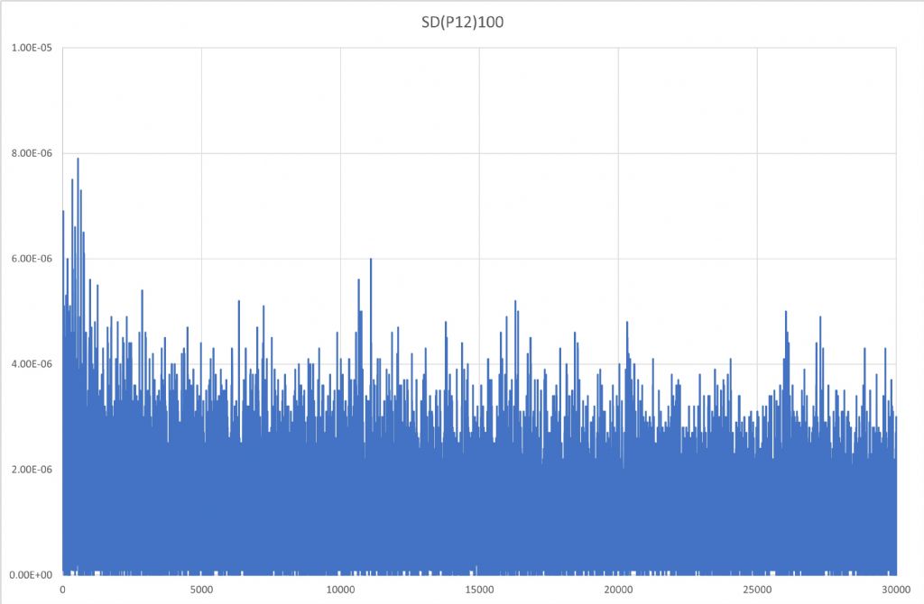
                    sd(p)_1.jpg

                    Now have first results from the lash-up, without amplitude control other than varying the drive voltage to the L298 that drives the Helmholtz coils. The trailing edge of the centre opto pulse clocks a D-type which is connected as a divide-by-2. The Q and nQ outputs are connected to the L298 control inputs to set the drive direction. The D-type toggles on the trailing (+ve going) pulse edge. The amplitude opto at the moment is just driving the "set" input of the D so that it "knows" which side the pendulum is. Initial tests were done with the supply voltage set to 7.5v which is a bit more than the minimum value to make sure that the 5v regulator that feeds the logic and picPET works. This proved to be more than enough to drive the pendulum to a maximum amplitude of 34mm (target 20mm) so plenty of drive in hand – I think I need some resistance in the coils to reduce the current. As the L298 drops nearly 2v in both sides of the drive the coil voltage is ~3v and current about 60mA. Should be around 40mA at target amplitude. The plot above shows the standard deviation of the pendulum period averaged over 100 successive measurements. Here the values are significantly less than 10us and of the same order as I was seeing in run-down tests without impulsing. The combination of the new spring, more rigid pendulum rod, and revised impulsing method seems to have done the trick. Now I can make progress!

                    #643361
                    John Haine
                    Participant
                      @johnhaine32865

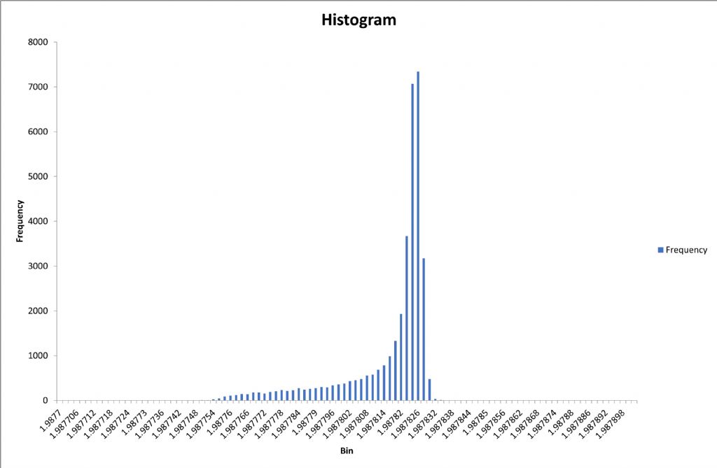
                      period_histo.jpg

                      And here's the histogram of the period.

                      #643368
                      SillyOldDuffer
                      Moderator
                        @sillyoldduffer
                        Posted by John Haine on 01/05/2023 11:48:36:

                        period_histo.jpg

                        And here's the histogram of the period.

                        Fascinating – I'd never have thought of the recoil trick.

                        Does applying recoil explain the bias towards shorter periods shown in the histogram? Or could it be caused by the amplitude control system?

                        Although the histogram shape suggests something isn't quite right, period only ranges over about 100uS, which is good in my experience.

                        Dave

                        #643370
                        John Haine
                        Participant
                          @johnhaine32865

                          The tail at the left is because the run started at a lower amplitude which built up to a steady-state value about 20,000 seconds in.

                          #643560
                          SillyOldDuffer
                          Moderator
                            @sillyoldduffer
                            Posted by John Haine on 01/05/2023 12:58:58:

                            The tail at the left is because the run started at a lower amplitude which built up to a steady-state value about 20,000 seconds in.

                            It's remarkable how long pendulums take to settle after a cold-start. By default I ignore the first 200 beats, sometimes more.

                            I've begun planning my start up procedure, which may take ages, mainly because the bob has to stabilise twice. Briefly:

                            • Apply vacuum
                            • Wait n minutes for pendulum to come to rest. (I expect pumping air out to vibrate it)
                            • Start the clock (by switching on the microcontroller)
                            • Wait n minutes for pendulum to settle (could be hours)
                            • Set period, temperature, pressure and drift coefficients
                            • Switch compensation on
                            • Set clock to UTC (UNIX time via NTP)
                            • Compare clock UTC to NTP UTC and correct the clock by sending it the difference. Repeat difference corrections until clock and NTP are closely synchronised

                            I like to keep things simple.

                            thinking

                            Dave

                            #644453
                            John Haine
                            Participant
                              @johnhaine32865

                              Well, mixed progress. As I was away last week for 4 days I left the clock running and logging data. This revealed a bug that I'd introduced into my logging software – the picPET rolls over after 100,000 seconds and this has to be detected but I had made a mistake with a new version that resulted in it adding 100,000 seconds to the times every beat! By Friday the clock seemed to have been running for the age of the known universe, before the logging program crashed! So I fixed that and started logging again on Saturday – checked the logs both yesterday morning and this morning and found I was getting occasional huge excursions of both amplitude and period. Looking closer this is clearly due to morning sun, which shines straight through the window on that side of the house on to the clock. I had this problem before. Fitting a black card sunshade in front of the sensor truck resulted in disturbing the wiring and that revealed a bad contact as well. Ho hum, the joys of clocks…

                              So, I have now fixed (I hope) the contact; fixed the logging bug; fixed a sunshade on the sensor and a black card background; and put a stool holding a piece of board in front of the clock to keep the sun off. Let's see what tomorrow brings…

                              #646472
                              John Haine
                              Participant
                                @johnhaine32865

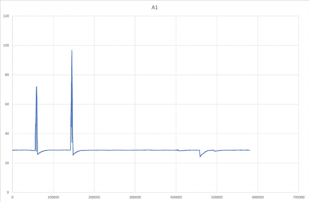
                                Having bodged shading all round the clock I logged a long run, here is a plot of amplitude vs. time over nearly a week.

                                recoil5_ampl.jpg

                                Most of the time it jogs along at ~28mm but with occasional glitches. The first two are a day apart, and after these I added some extra shading. Then we had a couple of dull early mornings so there was little change, but you can see a slight wiggle just after 400,000s. A day later there's a rather bigger one at ~460,000s. With this and some additional measurements using some special logging software that gave a real-time amplitude display I finally worked out what's going on.

                                Basically, the photo-interrupter is (no surprise) sensitive to ambient light. As the pin on the bob breaks the beam, because the beam has finite width the intensity of the light reaching the sensor ramps down as the beam is occluded, then ramps up again. Somewhere on the ramp the internal schmidt triggers. However the sensor responds to a wide wavelength range including the visible light, though the LED radiates mainly IR, so ambient light raises the whole sensed waveform up, and shortens the apparent pulse length which is interpreted as an increase in amplitude. This isn't real of course as the bob couldn't possibly respond this fast. There's also an apparent period error.

                                What's interesting is that there is also a real amplitude reduction from which the pendulum slowly recovers after the light effect has stopped. This is because the illumination does actually reduce the pulsewidth, and that in turn reduces the impulse for as long as the illumination by direct bright sunlight persists. With the real-time amplitude (actually pulse width) logger, I can see that actually the sensor is affected by quite sall variations – for example if I stand in front of the pendulum. So I've introduced another environmental influence on the pendulum! Ho-hum.

                                Apart from putting the whole thing in a light-tight box, there are a couple of simple ways to reduce ambient light. One is to fit a filter that only passes IR in front of the photo detector – I've found a source of this and it could be an easy win. The other is to put a collimating "tunnel" in front of the sensor to reject light not coming from the LED direction – that's a bit harder as it makes the gap narrower.

                                #646491
                                Bazyle
                                Participant
                                  @bazyle

                                  Posted by John Haine on 25/05/2023 18:23:27:

                                  The other is to put a collimating "tunnel" in front of the sensor to reject light not coming from the LED direction – that's a bit harder as it makes the gap narrower.

                                  If your sensor is sensitive enough can you move them further apart before adding the tunnel? I happen to have just ordered a sensor (for something else) which said it has up to 1" range and I had assumed I would use it at 1/4" but now you are making me rethink ambient light complications.

                                  #646499
                                  John Haine
                                  Participant
                                    @johnhaine32865

                                    Bazyle, exactly what I'm thinking if the filter and short tunnel don't work.

                                    #646511
                                    SillyOldDuffer
                                    Moderator
                                      @sillyoldduffer

                                      My clock bodges an Arduino collision detector module. It's a comparator rather than a Schmitt Trigger, so interesting to compare how the two misbehave when ambient light changes.

                                      I used a comparator rather than a Schmitt Trigger for a non-technical reason – Arduino modules are widely available and cheap! Of the two, I'd expect a Schmitt Trigger to do a better job.

                                      A comparator compares a signal voltage to a reference voltage set by the user. When the signal is lower than the reference voltage, the comparator outputs zero volts. When the signal is greater than the reference, the comparator flips and outputs 5V. A disadvantage is the circuit is sensitive to noise, and I had considerable trouble with it early on. Ambient light puts an unwanted voltage on the signal. In consequence, strong sunshine triggers the comparator whatever the pendulum is doing whilst, lesser brightness alters the effective sensitivity of the trigger, causing false triggering. Enclosing the pendulum revealed my sensor was also sensitive to legitimate IR from the sender bouncing off the moving pendulum, the shiny Aluminium structure, and the shiny white PVC case.

                                      A Schmitt trigger is also a comparator circuit, but uses positive feedback to the signal to flip the output. Not only is detection faster, but the circuit provides hysteresis. As with a comparator, the circuit triggers when the signal rises above a certain level, but hysteresis keep it triggered until the signal drops below a second, lower, trigger level. Hysteresis makes the Schmitt trigger less vulnerable to jitter, which is always present in beam break applications. John's description of how his Schmitt Trigger reacts to ambient light is valuable to me, because replacing my comparator with one is an obvious upgrade to my clock.

                                      Good news is the cure appears to be identical: shielding! I appear to have tamed my sensor by mounting the IR sender and receivers inside slotted tubes, lightproof at the rear. The slots narrow the beam considerably, making it harder for ambient light and reflections to cause trouble.

                                      One advantage of the Arduino comparator module is that the IR sensor and sender can both be unsoldered and rewired elsewhere to cover largish gaps. In contrast, many Schmitt trigger modules encase the sensor and sender within a limited gap: no problem when used to measure rpm, but a bit awkward for my design.

                                      I haven't proved yet that my comparator isn't good enough, but it's a strong possibility. John's observations are valuable because it's likely that I'll swap it for a Schmitt Trigger later.

                                      Dave

                                      #646540
                                      Michael Gilligan
                                      Participant
                                        @michaelgilligan61133
                                        Posted by SillyOldDuffer on 26/05/2023 09:46:22:

                                        […]

                                        One advantage of the Arduino comparator module is that the IR sensor and sender can both be unsoldered and rewired elsewhere to cover largish gaps. In contrast, many Schmitt trigger modules encase the sensor and sender within a limited gap: no problem when used to measure rpm, but a bit awkward for my design.

                                        .

                                        On a practical note : The unit that John uses can simply be sawn into two halves, to then be mounted separately.

                                        There is no electrical connection.

                                        MichaelG.

                                        .

                                        GP1A57HRJ00F

                                        https://docs.rs-online.com/7a93/0900766b81327ada.pdf

                                        Edited By Michael Gilligan on 26/05/2023 13:27:33

                                        #646551
                                        S K
                                        Participant
                                          @sk20060

                                          A Schmitt trigger is also vulnerable to noise, and probably a lot more so than a good comparator. It responds at a threshold like a comparator, and when crossing that threshold it's equally if not more vulnerable to noise. It's just that the hysteresis tends to disguise the existence of noise since it doesn't oscillate near the threshold like a comparator can. But the noise is still there in that the output will include substantial timing jitter about the threshold.

                                          You also can't set the threshold of a Schmitt trigger like you can with a comparator, as it's built into the trigger by transistor characteristics that you can't control. Its gain near the threshold (maybe 10-20?) is also a lot lower than a good comparator (thousands to millions).

                                          For better performance, putting gain in front of the trigger should help. So maybe be a fast, low-noise comparator followed by a Schmitt trigger.

                                          #646569
                                          Joseph Noci 1
                                          Participant
                                            @josephnoci1

                                            Depends what you think a Schmitt trigger is…

                                            It is merely a comparator with hysteresis. The venerable LM211 series , old as socks, is an easy to use device that does it all. Hysteresis is most often implemented through feedback from out to input on a comparator, and the difference in switch points can be set to anything you want, between rails. You can set the Schmitt range to anything you wish. It also has naught to do with the triggering characteristics of the transistors. A comparator without feedback can and does oscillate around the input switch reference point – the faster the comparator type, the worse it is. The LM211 takes around 100ns to switch state, and with a few % feedback you might have a 1 or 2us switching range from off to on to off, but as you would only look at one edge, eg, the ON edge to pulse the pendulum, you timing jitter would be less than 100ns…The LM211 , a comparator by definition and datasheet has a gain around switch point of near 10,000. A fast op-amp is also a good comparator, and with a few resistors, hysteresis is easy to implement.

                                            A fast comparator followed by a fast comparator with hysteresis ( a Schmitt trigger..) will lead to tears – the first one can and will generate a short train of high frequency square wave rail to rail oscillations at the trigger point, and the second will simply pass them straight through, since the input is going above and below the hysteresis switch points…And then one will try fix it by adding series resistors and caps to gnd to filter and slow it all down again.

                                            Edited By Joseph Noci 1 on 26/05/2023 17:05:00

                                            #646620
                                            S K
                                            Participant
                                              @sk20060

                                              A CMOS Schmitt trigger's switching points depends on transistor thresholds and sizes.

                                              Yes, sorry, a comparator followed by an SR flip-flop. That needs to be reset, though.

                                              #646633
                                              Joseph Noci 1
                                              Participant
                                                @josephnoci1
                                                Posted by S K on 26/05/2023 23:41:09:

                                                A CMOS Schmitt trigger's switching points depends on transistor thresholds and sizes.

                                                Yes, sorry, a comparator followed by an SR flip-flop. That needs to be reset, though.

                                                I think we are mixing technologies a little here – The 'CMOS' Schmitt I 'think' you are referring to would be a Logic element, ie, in the domain of AND, OR, NOT gates and similar stuff? Logic gates with Schmitt capability are VERY well defined in switch points – else gazillions of computers and phones would not work too well..The difference being that Schmitt logic gates have a rather small hysteresis zone, since the driving gates tend to be rather fast – low 10s of nanoseconds, even for CMOS…And that zone is not adjustable but defined at manufacture. It is well defined and controlled and specified in the data sheets.

                                                So, yes, it depends on transistor thresholds – yes , all Schmitts do, but that applies to all comparator types anyway – not just Schmitt. The point being that a comparator becomes a defined Schmitt when we apply Hysteresis – we don.t need to fiddle with its transistor sizes…

                                                If I have your Schmitt concept wrong, if it is not a logic element, and not a comparator, could you provide a part number for the Schmitt device you have in mind?

                                                #646638
                                                Michael Gilligan
                                                Participant
                                                  @michaelgilligan61133
                                                  Posted by SillyOldDuffer on 26/05/2023 09:46:22:

                                                  My clock bodges an Arduino collision detector module.

                                                  .

                                                  This discussion is getting interesting, but is a little short on hard facts

                                                  Could I trouble you please, to identify the specific ‘Arduino collision detector module’ and briefly describe your bodge.

                                                  Thanks

                                                  MichaelG.

                                                  #646652
                                                  SillyOldDuffer
                                                  Moderator
                                                    @sillyoldduffer
                                                    Posted by Michael Gilligan on 27/05/2023 08:10:16:

                                                    Posted by SillyOldDuffer on 26/05/2023 09:46:22:

                                                    My clock bodges an Arduino collision detector module.

                                                    .

                                                    This discussion is getting interesting, but is a little short on hard facts

                                                    Could I trouble you please, to identify the specific ‘Arduino collision detector module’ and briefly describe your bodge.

                                                    Thanks

                                                    MichaelG.

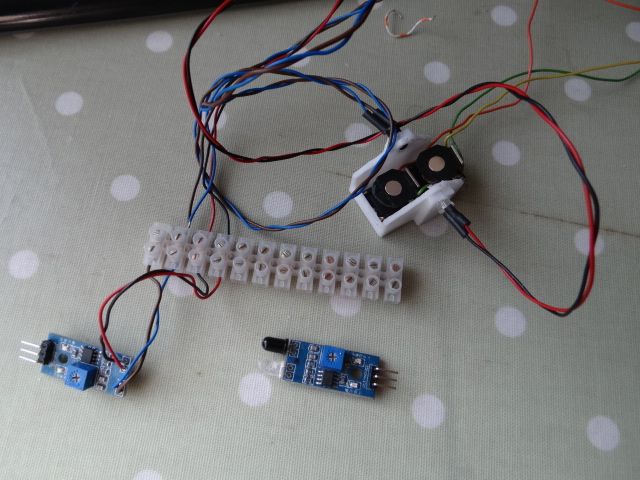
                                                    No problem. Two examples on the bottom of this photo, the right hand one is unmodified, The left hand one has been bodged by unsoldering the IR sender and photo-sensor and wiring them via choc-block terminals to the white holder. The bob breaks the beam as it swings between them. (The two electromagnets were an early experiment.)

                                                    dsc06308.jpg

                                                    The modules are very common, prices vary depending on source, this seller on Amazon is offering 20 for £12.99

                                                    The electronics are basic, consisting of an LM393 comparator chip, a pot, an IR LED, a phototransistor, a few resistors and a couple of indicator LEDs. Three pins: 5V, Ground, and Output.

                                                    The IR sensor and sender are ordinary, typical of the type found in TV remotes, with a wide beam – usually 35° Not ideal, but work reasonably well. They have to be protected against ambient light, and perform better when contained in tubes that narrow the beam. My tubes are slotted at the output end, and can be rotated to angle or narrow the effective aperture.

                                                    I'm finding SK and Joe's comments on Comparators and Schmitt triggers interesting. It's yet another aspect of pendulum design with hidden depths. Although I know a bit about Op Amps, Comparators and Schmitt Triggers, I'm not an expert! When reading their comments, bear in mind that John and I are both using modules rather than bespoke circuits. I don't think either of us are keen to build SMD circuits! So although the trigger points of a Schmitt Trigger circuit can be altered with a some sums and a pair of resistors, John might have trouble changing the resistors buried inside his encapsulated module. Likewise, though I could reconfigure the Arduino module as a Schmitt Trigger, it's hard for Mr Clumsy here to do.

                                                    Dave

                                                    #646663
                                                    Michael Gilligan
                                                    Participant
                                                      @michaelgilligan61133

                                                      Thanks, Dave … that all makes sense

                                                      The only ‘Arduino collision detector module’ that I had previously seen uses a microswitch …

                                                      MichaelG.

                                                    Viewing 25 posts - 76 through 100 (of 103 total)
                                                    • Please log in to reply to this topic. Registering is free and easy using the links on the menu at the top of this page.

                                                    Advert

                                                    Latest Replies

                                                    Viewing 25 topics - 1 through 25 (of 25 total)
                                                    Viewing 25 topics - 1 through 25 (of 25 total)

                                                    View full reply list.

                                                    Advert

                                                    Newsletter Sign-up