Yet another Arduino clock thread!

Advert

Yet another Arduino clock thread!

Home Forums Clocks and Scientific Instruments Yet another Arduino clock thread!

Viewing 25 posts - 51 through 75 (of 103 total)
  • Author
    Posts
  • #633446
    John Haine
    Participant
      @johnhaine32865

      As it's been a couple of weeks I thought a quick progress report was due.

      • I finished the time logging system and got some initial Pi logging software working the w/e of the 4/5 Feb. That was logging the time of each swing, i.e. every second, but the results were difficult to process since the two swings are slightly different lengths as measured. Anyway the results were good enough to see the effect of the Turkey earthquake on amplitude and rate.
      • New logging software installed last Tuesday and ran for nearly 5 days but I found the pendulum nearly stationary early in the morning of the 5th day. I'd noticed before that occasionally when I was working near the clock it would "forget" which side was left, which meant that the impulse actually slowed the pendulum down! This time I also found that there were no pulses coming from the optos and finally found the bad contact in the DC supply to the LEDs.
      • As I had to restart the clock anyway I made another software update. Now the Pi for each cycle generates a record that has the acquisition time based on a "paper clock" that has the average period of the real clock; the error between the "clock time" based on the integrated measured period and the paper time; the period itself; amplitude averaged over the two opto pulse lengths; temperature, pressure, and RH.
      • The reason for choosing the parameters and format is so I can directly read the data into either of two free software packages for analysis: TimeLab and Stable32. Both easy to find on the web, and recommended in Tom Van Baak's writings. I can't say I'm anything more than a novice with either, but they seem reasonably easy to use and can compute things like Alan Variance with a button push. I'll also use R-Studio to extract regression data. So far there hasn't been much variation in atmospheric conditions against which to correlate! I think I'll also add an LDR to look at ambient light levels to see if there's any systematic affect on the opto precision. Would also be good to log supply volts!
      • I did manage to get a nice plot of time drift out of Stable32 from the week's worth of data but now I can't work out how to get it back!
      Advert
      #633451
      Tony Jeffree
      Participant
        @tonyjeffree56510
        Posted by John Haine on 14/02/2023 16:26:51:

        Posted by Tony Jeffree on 29/01/2023 16:57:43:

        John – your use of core-less coils to drive the pendulum prompted me to unearth a couple of coils that I had to hand that were bought as components for a loudspeaker crossover. Thes kinds of coils can be readily purchased from the usual electronic supply suspects, are beautifully wound, and come in a wide variety of sizes. An easy solution that avoids the need for coil winding. The ones I unearthed are wound from 0.4mm copper wire, and have about a dozen layers of 25 turns.

        Edited By Tony Jeffree on 29/01/2023 17:05:51

        Would be good to know where they came from Tony*. But HH coils are quite easy to make and you have the advantage then of a predictable flux density so the current needed can be calculated. But if I ever make another one I might well buy two of those coils…

        * https://willys-hifi.com/collections/audio-inductors-air-core ?

        I don't recall where those particular ones came from John, but Willys would be one of the places I would look, also Mouser and RS Components.

        #633452
        Tony Jeffree
        Participant
          @tonyjeffree56510
          Posted by John Haine on 14/02/2023 16:26:51:

          Posted by Tony Jeffree on 29/01/2023 16:57:43:

          John – your use of core-less coils to drive the pendulum prompted me to unearth a couple of coils that I had to hand that were bought as components for a loudspeaker crossover. Thes kinds of coils can be readily purchased from the usual electronic supply suspects, are beautifully wound, and come in a wide variety of sizes. An easy solution that avoids the need for coil winding. The ones I unearthed are wound from 0.4mm copper wire, and have about a dozen layers of 25 turns.

          Edited By Tony Jeffree on 29/01/2023 17:05:51

          Would be good to know where they came from Tony*. But HH coils are quite easy to make and you have the advantage then of a predictable flux density so the current needed can be calculated. But if I ever make another one I might well buy two of those coils…

          * https://willys-hifi.com/collections/audio-inductors-air-core ?

          I don't recall where those particular ones came from John, but Willys would be one of the places I would look, also Mouser and RS Components.

          #633474
          Joseph Noci 1
          Participant
            @josephnoci1
            Posted by John Haine on 14/02/2023 17:10:39:

            As it's been a couple of weeks I thought a quick progress report was due.

            • ………
            • The reason for choosing the parameters and format is so I can directly read the data into either of two free software packages for analysis: TimeLab and Stable32. Both easy to find on the web, and recommended in Tom Van Baak's writings. I can't say I'm anything more than a novice with either, but they seem reasonably easy to use and can compute things like Alan Variance with a button push.

            John , not sure if I missed it, but did you describe your measurement method/process? I did not see a clear reference in your posts?

            Timelab/Stable32 process data that is in essence the result of a determination of variation of data samples in a accurate, fixed time interval – a Time interval Counter that has a very accurate and stable clock being gated or counted by the pendulum period. The clock count variation can then be processed by these software. Is that what you have implemented? If so, your source clock drift / variation/accuracy can mask the true Allen Variance if it's not good…

            #633503
            John Haine
            Participant
              @johnhaine32865

              Hi Joe, no I don't think I did. I use one of Tom's picPETs (a pP07) to time both edges of the pulses from the BDC opto. The pP is clocked from a 10MHz OCXO, non-disciplined but likely to be a lot more accurate than my clock!

              #633516
              Michael Gilligan
              Participant
                @michaelgilligan61133

                On the subject of ‘reference oscillators’ …

                I was intrigued by this ebay offering : **LINK**

                https://www.ebay.co.uk/itm/283982709540

                There appear to be contradictory ‘stability’ figures in the description, and its easy screwdriver adjustability seems rather counter-intuitive for something intended as a reference device.

                … Grateful for comments from those better-informed.

                MichaelG.

                #633519
                Joseph Noci 1
                Participant
                  @josephnoci1
                  Posted by Michael Gilligan on 15/02/2023 00:53:43:

                  There appear to be contradictory ‘stability’ figures in the description, and its easy screwdriver adjustability seems rather counter-intuitive for something intended as a reference device.

                  MichaelG.

                  A useful reference for CB radio's maybe… else its just an exercise in frustration! All high quality Ref oscillators will have some form of adjustment but with limited range – the NDK osc you reference can be changed by 500Hz typ with that trimmer, which is a ceramic trim cap, with its own poor temp performance and mechanical stability. Would not touch it with a trimmer screwdriver – or a barge pole for that matter..

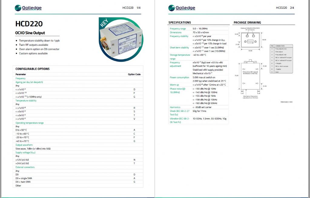
                  One of the OCXO's I use as an example:

                  jn_ocxo spec.jpg

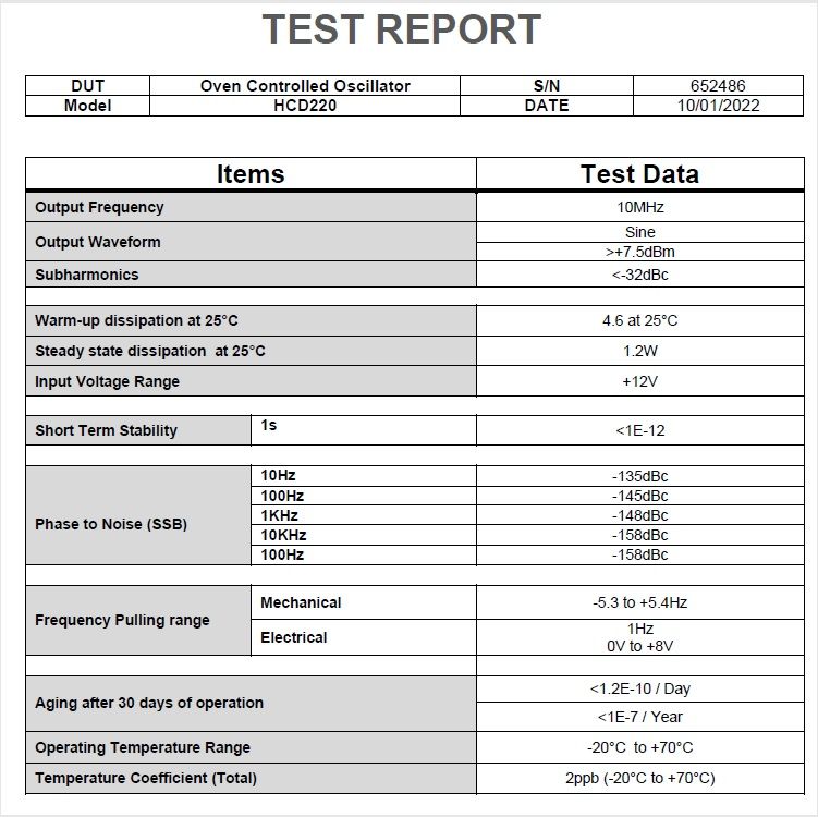
                  And the test sheet:

                  jn_osc_test sheet.jpg

                  #633520
                  Joseph Noci 1
                  Participant
                    @josephnoci1
                    Posted by John Haine on 14/02/2023 22:17:46:

                    Hi Joe, no I don't think I did. I use one of Tom's picPETs (a pP07) to time both edges of the pulses from the BDC opto. The pP is clocked from a 10MHz OCXO, non-disciplined but likely to be a lot more accurate than my clock!

                    John, I believe from some previous interaction with you that you are a time-nut? At the risk preaching to the converted, here are some useful reads – ( I cannot post pdfs, etc, so the google should find them for you)

                    A very good ppt presentation by a master in the field:

                    **LINK**

                    A veritable bible on the subject: Handbook of Frequency Stability analysis.

                    **LINK**

                    Some measurement systems:

                    **LINK**

                    And Misc good stuff:

                    **LINK**

                    **LINK**

                    WJ Riley is a master in this field…

                    Obviously you will have the Stable32's manual…


                    Edited By Joseph Noci 1 on 15/02/2023 06:13:53

                    #633521
                    Michael Gilligan
                    Participant
                      @michaelgilligan61133
                      Posted by Joseph Noci 1 on 15/02/2023 05:49:08:

                      Posted by Michael Gilligan on 15/02/2023 00:53:43:

                      There appear to be contradictory ‘stability’ figures in the description, and its easy screwdriver adjustability seems rather counter-intuitive for something intended as a reference device.

                      MichaelG.

                      A useful reference for CB radio's maybe… else its just an exercise in frustration! All high quality Ref oscillators will have some form of adjustment but with limited range – the NDK osc you reference can be changed by 500Hz typ with that trimmer, which is a ceramic trim cap, with its own poor temp performance and mechanical stability. Would not touch it with a trimmer screwdriver – or a barge pole for that matter..

                      […]

                      .

                      Thanks, Joe … My instinctive caution about it seems to have been appropriate.

                      Much appreciated

                      MichaelG.

                      #633541
                      John Haine
                      Participant
                        @johnhaine32865

                        Thanks for the links Joe. Some I had seen, they all look useful. I am trying hard not to get sucked in to being a time-nut any more than I have to, I'm mainly interested just in making accurate pendulum clocks – but how do I know how accurate?! I assume my cheap eBay OCXO is a lot better than my pendulum but how to check?

                        #633563
                        SillyOldDuffer
                        Moderator
                          @sillyoldduffer
                          Posted by John Haine on 15/02/2023 09:51:01:

                          Thanks for the links Joe. Some I had seen, they all look useful. I am trying hard not to get sucked in to being a time-nut any more than I have to, I'm mainly interested just in making accurate pendulum clocks – but how do I know how accurate?! I assume my cheap eBay OCXO is a lot better than my pendulum but how to check?

                          The same problem is on my list! John pointed me at a cheap source of ex-equipment OCXO, CTI Type OSC5A2B02, which is a 10MHz 200ppb device. Although this is a low-end OCXO, it's a better frequency standard than anything else I have.

                          But, the frequency is not 10MHz out-of-the-box, the user is expected to adjust a pot to tune it in. The question is, how to tune it in accurately. I need a more accurate frequency standard and a way of comparing the two.

                          Possibilities open to me are:

                          • I have GPS seconds pulses, which could be used with a precision event time to get close to 10MHz
                          • With much more bother, one of the radio time signals could be used:
                            • WWV (10MHz. weak, noisy and not always audible),
                            • RWM (9.996MHz, louder than WWV here)
                            • MSF (60kHz, weak in my location),
                            • DCF77 (77kHz, bit louder than MSF)
                            • BBC R4 longwave (198kHz, very strong but amplitude modulated),
                            • ALS162 (Allouis, France 162kHz, good signal and not amplitude modulated)

                          My plan is to divide the OCXO by two because an Arduino timer can only be externally clocked below 6.4MHz and programmed to count pulses over several seconds to get the average frequency. Alternatively, do similar with a picPET at 10MHz, noting that the picPET can't be programmed to average counts, but this could be done externally.

                          I'm not expecting the GPS/PETmethod to do a brilliant job because the resolution of 5MHz into a binary counter is ±1Hz. Is this good enough, given that I think that 200ppb at 10MHz is 2Hz? True confession : my maths are untrustworthy.

                          Initial experience watching an OSC5A2B02 power up with an oscilloscope is that stability is very poor at first – the waveform visibly increases in frequency from cold for about 10 seconds. The specification says don't trust it for at least half an hour after power on. The device is not meant to be switched on and off rapidly. I'd expect operating it in the open air to reduce stability compared with mounting it in a closed box that slows down heat loss and minimises convection.

                          Getting a 'near enough' 10MHz signal is easy, but getting an accurate, stable 10MHz signal and proving it's right seems horribly difficult!

                          I've toyed with measuring frequency from first principles with a Lecher line, but that seems to require measuring a 15 metre-ish long line with sub millimetre accuracy, also a serious challenge!

                          Dave

                          #633577
                          Joseph Noci 1
                          Participant
                            @josephnoci1

                            Dave, check my post in your post re using a 1pps programmable GPS as a ref clock…

                            #634687
                            John Haine
                            Participant
                              @johnhaine32865

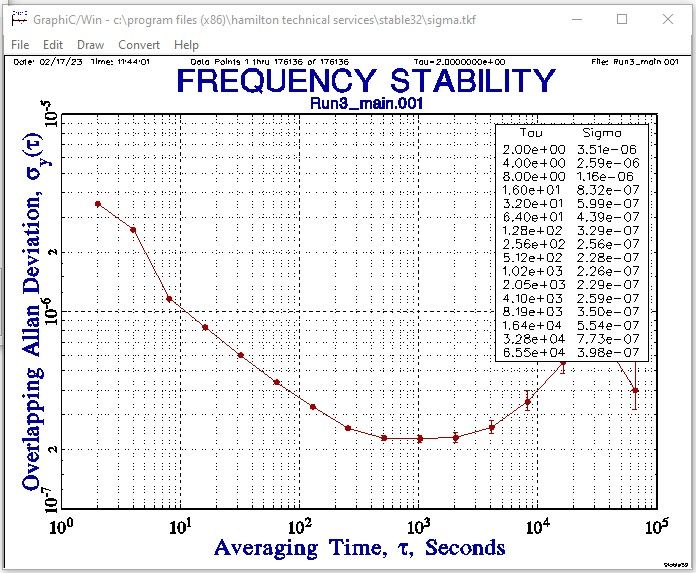
                              I thought it was about time I posted some results from the clock, so to start with here is an ADEV plot from the first extended run (nearly a week I think). (I also posted this on Dave's current thread.)

                              jh6_ava.jpg

                              I'm not entirely sure what it means but TVB says it looks respectable, comparable so far with a good Synchronome except the 'nome plot would look awful below 30s averaging time from impulse noise whereas this is clean down to the 2s impulse period. Variation fllor at about 1000s then rises up again. Next step is to extract some timekeeping data from the numbers.

                              #635052
                              John Haine
                              Participant
                                @johnhaine32865

                                Well not going as well as I hoped – I feel for Dave in his frustrations! Looking more at the data to try to extract some regression coefficients I got increasingly concerned about the apparent noise in the time measurements and by extension in the amplitude calculations. After quite a lot of playing around there are a number of things to investigate.

                                • I think some of the problem may be accidental rounding in the Python code that reas the data from the picPET. The pP encodes each timestamp as a 13 digit BCD decimal with a decimal point, so 7 digits after the point and 6 before. The count rolls over at 100,000 seconds and the code has to detect a rollover between any two edges and adjust itself to add an appropriate number of 100,000 seconds. I was storing each measurement as a float but the precision of that in Python is limited in the number of decimal digits. When I looked at some of the recoded data I could see that though there were 7 decimal places the actual precision was more like 5 as some rounding took place. It seems that I should be using "Decimal" types rather than float which is the next thing to try.
                                • There's also electrical noise on the sensor and worse perhaps on the picPET. The whole thing is powered from a switched-mode 12v wall wart, with a buck converter to 5V for most of the electronics and boost to 18v adjustable for the drive coils. I'll see if I have a 12v transformer type wart and fit a linear regulator for the 5v.
                                • I'm also concerned that there could be some pendulum wobble, either in the spring compliance or the rod bending (or both!). Whether that matters I don't know – I think it would show in the ADEV plot so maybe not. But the measurement noise must be affecting the ADEV, of course the snag with electronic monitoring is making sure that I'm looking at the pendulum and not the tester!

                                Ho hum.

                                #635082
                                SillyOldDuffer
                                Moderator
                                  @sillyoldduffer
                                  Posted by John Haine on 26/02/2023 10:14:29:

                                  Well not going as well as I hoped – I feel for Dave in his frustrations! Looking more at the data to try to extract some regression coefficients I got increasingly concerned about the apparent noise in the time measurements and by extension in the amplitude calculations. After quite a lot of playing around there are a number of things to investigate …

                                  Ho hum.

                                  Welcome to my world! When a pendulum clock is tested in the ordinary way, I suspect a multitude of sins are covered up because many errors tend compensate out on average.

                                  Collecting a lot of fine-grained data, especially with a Precision Event Timer watching individual swings through a statistical microscope reveals a multitude of anomalies, as does watching drift and amplitude vary over longer periods. Possibly many a clockmaker would be shocked to see just how variable clocks are when closely inspected. No shame in it, because even the world's best timekeepers have limitations. I found recently that Atomic Clocks don't have wonderful short-term stability, and are often complemented by an OCXO which do. The OCXO doesn't have excellent long-term stability, but that part of the problem is covered by the Atomic Clock. Team work!

                                  Which picPET are you using? Tom provides a number of variants and one of the others may be more suitable. (An advantage of my ardPET is the source code being available allows a C-savvy user to program the output in any format.)

                                  I've managed to avoid using 64bit floating point in the Arduino by working within the limits of long integers, for example using a pair of them to represent seconds and microseconds rather than a narrow float. Likewise, I've just avoided python Decimal, which is good because they're slow to compute and the numpy module is designed for speedy doubles. Special care is needed to avoid and spot underflow and overflow problems.

                                  Electrical noise is a problem, but I'm pretty sure most of mine is coming from the pendulum and the beam break sensor. My pendulum is relatively poorly made. In particular, the suspension is prone to twist whilst the spring is also liable to be biassed by levelling and alignment errors. Most test runs after a mechanical adjustment show prolonged small changes that gradually disappear and different oscillation modes. I think these are due to the suspension 'running in'. The different oscillations appear when impulse is increased and are probably due to the rod 'twanging'.

                                  Understanding "wos goin on" is interesting, but only important if the goal is a high-performance clock, one delivering high short-term and long-term stability. That can be built by me on the cheap!

                                  Dave

                                  #635083
                                  John Haine
                                  Participant
                                    @johnhaine32865

                                    pP07 – seems designed for pendulum clocks. I don't think computation speed will be an issue at 1 record/sec! We'll see how it goes with Decimal…

                                    #635140
                                    John Haine
                                    Participant
                                      @johnhaine32865

                                      Actually after working out the syntax it was fairly easy and I'm now logging the data at full precision. Will see what the stats look like now…

                                      #635172
                                      SillyOldDuffer
                                      Moderator
                                        @sillyoldduffer
                                        Posted by John Haine on 26/02/2023 17:46:30:

                                        Actually after working out the syntax it was fairly easy and I'm now logging the data at full precision. Will see what the stats look like now…

                                        If anyone is curious about what we're on about, it's limitations in the accuracy of computer arithmetic. How many digits they can manage, how fast sums can done, and booby traps – several.

                                        The fastest comuter arithmetic is done with word sized integers, usually 64bits on a modern PC. These hold up to 2^64 bits, holding unsigned numbers up to 18446744073709551616 or signed numbers ±9223372036854775808 If the 64bit range is exceeded, 64bit numbers roll-over with strange results: 18446744073709551616 + 1 = 0 And because integers don't support fractional parts, 1 / 2 = 0

                                        Floating point numbers support 1/2 = 0.5 but, in their fastest form, are also squeezed into 64bits. As a result, they are limited to 16 digits total. 1234567890123456.0 is ok, and so is 0.1234567890123456, but adding them together results in 1234567890123456.0 because all 16 digits have been used. The range of numbers they can hold is odd too: 1.7976931348623157e+308 to 2.2250738585072014e-308

                                        Programmers have to be careful to keep calculations within the limits of integers and floats, which is tricky when working with lots of seconds and microseconds, or nanoseconds.

                                        Other ways of computing big numbers exist but there's no such thing as a free lunch! Python3 integers are limited only by the amount of memory available and can be as long as a telephone line! Python also supports a Decimal type in which numbers are held precisely. Default precision is 28 digits, and this can be increased as required. The downside of unlimited precision is the numbers take up memory and calculations are relatively slow. These speed and space considerations become ever more important as the dataset grows.

                                        It's one of the many things software engineers are paid to get right! And sometimes they don't…

                                        Dave

                                        #635210
                                        Joseph Noci 1
                                        Participant
                                          @josephnoci1
                                          Posted by SillyOldDuffer on 26/02/2023 11:35:51:

                                          ………...I found recently that Atomic Clocks don't have wonderful short-term stability-
                                          A rather blatant statement Dave….Such clock sources deliver typical short term stabilities (1sec) of 10 minus 12 ( which is rather wonderful) and 5 day terms of 10 minus 15, which is really wonderful…
                                          and are often complemented by an OCXO which do.
                                          Hardly ever, if ever at all….It takes a high pedigree OCXO to come close to the atomic clock performance and regulating it to better than atomic standard would demand an exceptional device…
                                          The OCXO doesn't have excellent long-term stability, but that part of the problem is covered by the Atomic Clock. Team work!
                                          OCXO's of 10 minus 13 short term stab are available – if you are rich – typical costs for OCXO's :
                                          10 minus 9 – USD500
                                          10 Minus 12 – USD3500
                                          10 minus 13 – USD6500

                                          #635239
                                          SillyOldDuffer
                                          Moderator
                                            @sillyoldduffer
                                            Posted by Joseph Noci 1 on 27/02/2023 07:07:42:

                                            Posted by SillyOldDuffer on 26/02/2023 11:35:51:

                                            ………...I found recently that Atomic Clocks don't have wonderful short-term stability-
                                            A rather blatant statement Dave….Such clock sources deliver typical short term stabilities (1sec) of 10 minus 12 ( which is rather wonderful) and 5 day terms of 10 minus 15, which is really wonderful…
                                            and are often complemented by an OCXO which do.
                                            Hardly ever, if ever at all….It takes a high pedigree OCXO to come close to the atomic clock performance and regulating it to better than atomic standard would demand an exceptional device…
                                            The OCXO doesn't have excellent long-term stability, but that part of the problem is covered by the Atomic Clock. Team work!
                                            OCXO's of 10 minus 13 short term stab are available – if you are rich – typical costs for OCXO's :
                                            10 minus 9 – USD500
                                            10 Minus 12 – USD3500
                                            10 minus 13 – USD6500

                                            I was thinking of the clocks used on GPS satellites rather than the best that can be done on the ground.

                                            As I understand it, GPS satellites contain an OCXO disciplined by a practically sized Atomic Clock, not itself capable of the best possible Atomic accuracy, or short term stability. So an OCXO provides sub-second time, whilst the Atomic clock keeps the OCXO accurate in the long term.

                                            As the combination still isn't stable enough, the Atomic Clock's drift is measured by ground-stations who send it error corrections. I don't think the frequency of the Atomic Clock is tweaked, rather the corrections are applied mathematically as necessary to keep the OCXO and long count on target. A GPS satellite OCXO is unlikely to be the modest device I bought off ebay. The catalogues show high-end OCXO's get very expensive!

                                            I think the architecture is typical: a low quality oscillator does the day job, but is periodically corrected by a higher-standard, itself part of a hierarchy of time-standards,each of which gets more expensive and specialised as they struggle to deliver the best time technology can currently achieve.

                                            It's a fascinating subject and everything I thought I knew about it turns out to be wrong. What fun!

                                            Dave

                                            #635240
                                            John Haine
                                            Participant
                                              @johnhaine32865
                                              Posted by SillyOldDuffer on 27/02/2023 12:05:27:

                                              Posted by Joseph Noci 1 on 27/02/2023 07:07:42:

                                              Posted by SillyOldDuffer on 26/02/2023 11:35:51:

                                              ……. I don't think the frequency of the Atomic Clock is tweaked, rather the corrections are applied mathematically as necessary to keep the OCXO and long count on target. ……..

                                              Dave

                                              Tweaking atomic clock frequency must be a bit hard by definition!

                                              #635488
                                              John Haine
                                              Participant
                                                @johnhaine32865

                                                Well, as expected the wall wart (switched mode type) was horribly noisy and there were spikes all over the power rails, so I replaced my internal 5v regulator with a good old-fashioned linear type and ran the whole thing from a bench power supply. That didn't help much! Then I connected the 1pps from my GPS (same type as Dave has) into the picPET input rather than the opto signal from the pendulum – this gave a rock-solid set of readings that showed my OCXO frequency was 10Hz low… One more thing to try is feeding the 1pps signal into the emitter of the opto pickup in case the noise is getting in at the sensor (clutching at straws here…). But I'm coming reluctantly to the conclusion that my impulsing method is exciting "rod wobble"…! The rod being 6mm carbon fibe tube is a bit bendy, and the spring suspension pivot doesn't provide very strong lateral constraint – I was always concerned that my "clever" technique would give this problem, it's something that plagues synchronomes too. Have to think of a way to impulse close to the bob. Back to the drawing board…

                                                #635524
                                                SillyOldDuffer
                                                Moderator
                                                  @sillyoldduffer
                                                  Posted by John Haine on 01/03/2023 12:11:29:

                                                  Then I connected the 1pps from my GPS (same type as Dave has) into the picPET input rather than the opto signal from the pendulum – this gave a rock-solid set of readings that showed my OCXO frequency was 10Hz low…

                                                  Possibly the piCPET has the same bug I've just fixed in my ardPET.

                                                  Yesterday I replaced the horrible trimmer in my OCXO with a decent multi-turn type, thanks Duncan, and tested it.

                                                  Noticed something odd. The latest version of my ardPET optionally allows counts to be taken over 'n' GPS seconds, and I noticed that the 10x setting allowed the OCXO to be trimmed to 50000000, but the maximum count at x1 was always several Hz low. The x1 setting was missing some counts.

                                                  The only difference in the code between x1 and x10 was how often the counter is zeroed as a fraction of the total count; that suggested a logic error. In the program I reset the counter because doing so simplified the logic and maths, but engaging brain showed it's a bit too simple. Zeroing the counter loses any counts arriving immediately after an input capture event and before the next count cycle starts, plus counts that arrive whilst the zero instruction is being executed.

                                                  I've refactored the code so that the overflow and counter are only read by my code. The maths and logic needed to calculate the number of pulses between events is a little more complicated, but now the OCXO trims properly and 1x and 10x agree.

                                                  In an earlier comparison picPET and ardPET produced the same low result from the OCXO, which is why I thought the OCXO was wrong. It's possible picPET has the same logic flaw. I didn't realise anything was wrong with ardPET until measuring an OCXO pushed it to the limit. The error is only about 0.0001%, and unlikely to be spotted measuring a pendulum!

                                                  Corrected version of ardPET available on dropbox.

                                                  Dave

                                                  #636269
                                                  John Haine
                                                  Participant
                                                    @johnhaine32865

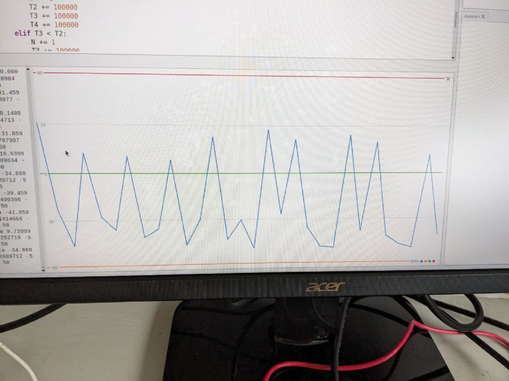
                                                    A bit more experiment seems to confirm that I have a case of the dreaded wobbly rod. I modified the logging code to just compute and print successive periods, or rather the deviation of the period from the mean, that latter being slowly updated as a moving average over 100 periods. Then used the plot function in the Python Shell to see what the result is.pxl_20230305_113812882.jpg

                                                    A typical plot showing how the period varies by +/- 25us between periods. What I think is happening is that because the rod is rather flexible, the impulse torque "winds it up" since the bob can't be instantly accelerated – the actual impulse is then delivered late and the rod probably has a flexure oscillation mode as well that will create additional measurement error. So I've decided I need to change tack and will make a kind of "yoke" that fits at the top of the bob with "wings" at either side in which will be mounted neo bar magnets. I've bought a couple of the "crossover coils" that Neil mentioned to use as the impulse electro-magnets. I have a scrap bit of tufnol that will do the job, just drawn it up in Cambam for the CNC mill. A side benefit is that I can try using a thinner pendulum rod – I have some 3mm CF tube which should have a smaller aerodynamic profile.

                                                    #636455
                                                    S K
                                                    Participant
                                                      @sk20060

                                                      Just an aside, as it slightly irritates me: What's with the "Precision Event Timer" talk, capitalized and all like it's a Very Real Thing!?

                                                      The long-accepted term for such a device is "time to digital converter" or TDC. 😉

                                                      (In a prior career ages ago, I designed a TDC with 500 ps resolution.)

                                                      Edited By S K on 06/03/2023 21:20:35

                                                    Viewing 25 posts - 51 through 75 (of 103 total)
                                                    • Please log in to reply to this topic. Registering is free and easy using the links on the menu at the top of this page.

                                                    Advert

                                                    Latest Replies

                                                    Viewing 25 topics - 1 through 25 (of 25 total)
                                                    Viewing 25 topics - 1 through 25 (of 25 total)

                                                    View full reply list.

                                                    Advert

                                                    Newsletter Sign-up