XY Table, or XZ gantry?

Advert

XY Table, or XZ gantry?

Viewing 16 posts - 1 through 16 (of 16 total)
  • Author
    Posts
  • #577001
    Dave S
    Participant
      @daves59043

      Contemplating a small build.
      I want to end up with about 150 x 150 mm travel XY and something like 150 mm Z clearance.

      I think a fixed gantry over a 200 x 200 table feels like a good rough size.

      Question is:

      Option 1 – fix the Z in the middle of the gantry – so it moves up and down but not side to side.

      This means the gantry supports have to be wider apart, but the z is on a single slide and xy is fairly simple to arrange. Does mean the X motor has to move with the table.

      or:

      Option 2 – go XZ in the gantry, which means the table only moves in Y but the spindle is 2 slides away from the fixed gantry, and the z motor has to move.

      Option 1 increases the footprint of the machine, but for a small machine like this I think it should give a better result.
      This will be a fabricated frame (probably steel weldments) with linear rails for the movements.

      Comments welcomed.

      Dave

      Advert
      #15372
      Dave S
      Participant
        @daves59043
        #577007
        Clive Foster
        Participant
          @clivefoster55965

          Back in the day small (and large) planers were made XZ on the gantry. I imagine there were good mechanical reasons for that choice.

          Despite our modern ready access to decent quality components at the wave of a credit card I always feel that the fundamental geometrical limitations of machine we can realistically build are closer to pre WW1 and inter war products than modern factory builds.

          Clive

          #577016
          Dave S
          Participant
            @daves59043

            Planers XZ gantry makes perfect sense, They only take a cut on the Y, so the X and Z can be locked during the cut.

            I think XY might make more sense for a mill, but it does cost in footprint and materials, so cheapest build would be XZ (just thinking why most cheap eBay specials are XZ)

            Dave

            #577026
            Robert Atkinson 2
            Participant
              @robertatkinson2

              A X-Y table and Z gantry takes at least 50% more X width. All else being equal the Z mounting will be less rigid. However as there is no change in load point it is easier to predict any flex and it will be consistent regardlesss of XY position.
              As usual it is a compromise between volume, accuracy, speed, weight, cost etc.
              The application matters. Machining, printing, laser? How heavy is the table and work holding? If the table and mounted workpiece are heavy keep them fixed. Have a gantry traveling in X allong the table, Y on gantry cross beam and Z on Y.

              Robert G8RPI.

              #577033
              Dave S
              Participant
                @daves59043

                Oops, forgot some fundamental basics…

                This is for a CNC milling machine. Small (relatively) parts, but in most metals, including stainless, aluminium, possibly some titanium, brass/ bronzes, “normal” steels. I think maximum metal stock size of 100mm cubes is all I’ll ever need for this machine, and may design it for that, but sizing to 150 at design time is a lot cheaper than building another machine in a bit.

                Spindle upto 10mm diameter cutters.

                I think the increase in footprint is not an issue for xy vs y only movements. I can make a z only gantry as rigid as a short XZ one – increased material cost but that’s ok.

                Dave

                #577045
                Anonymous

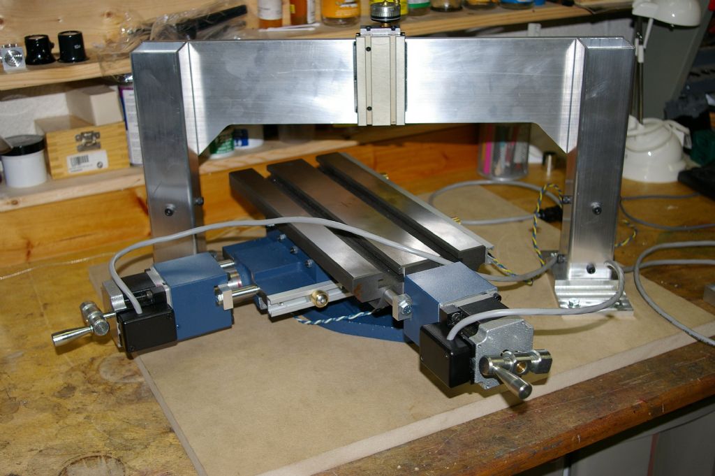
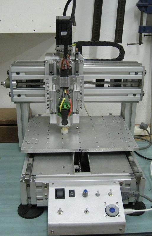
                  Something like this:

                  xyz-table-1.jpg

                  #577049
                  duncan webster 1
                  Participant
                    @duncanwebster1

                    with x on the table the gantry has to be ~twice as long, so for the same cross section it will be ~1/8 as stiff. Obviously it can be beefed up, but that costs money. As others have said it also takes up twice the space

                    #577060
                    pgk pgk
                    Participant
                      @pgkpgk17461

                      Is there any point in considering a rotary table with a fixed gantry with XZ ? Assuming one can get one's head around programming it..

                      pgk

                      #577061
                      Joseph Noci 1
                      Participant
                        @josephnoci1
                        Posted by pgk pgk on 28/12/2021 05:45:47:

                        Is there any point in considering a rotary table with a fixed gantry with XZ ? Assuming one can get one's head around programming it..

                        pgk

                        Makes for a concise and neat structure, and can be very rigid, but there are some non-trivial issues. Rotary table backlash is difficult to eradicate, and does not stay so for long – eliminating backlash in ball screws is easier. And then the software is not simple – you need good polar kinematics, with all the issues of the ArcTan near workpiece centre of rotation ( requiring very rapid – instant- rotations of the table as the cutter passes centre). I have just done this with a C axis / live tool implementation on a lathe, which IS simply an XZ mill with rotary table, on its side…It was painfull

                        I would not go that route for a 'simple' mill. Not to mention Linuxcnc…

                        An XZ gantry works well for such use.

                        My 'engraver' – very sturdy – table is a bit bigger than A4 size. Table moves in Y. Machine weighs around 36kg.

                        Mini-Router/Engraver


                        Peter – this looks interesting – the gantru appears bolted down so I assume this is the operating construction – interesting kinmatics here with a linear angle transform. All perpendicular cuts require angular transforms…

                        xyz-table-1.jpg

                        Edited By Joseph Noci 1 on 28/12/2021 06:26:04

                        Edited By Joseph Noci 1 on 28/12/2021 06:26:59

                        #577063
                        JasonB
                        Moderator
                          @jasonb

                          I have always considered gantry type machines best suited to larger XY and smaller Z movement. Now that you have given an idea of what you want to machine and sizes I would view your machine more as a vertical mill or VMC with an additional support to the column in which case have XY movement on the table and Z only on the head/gantry.

                          You have not said what sort of spindle you are thinking of using? integral ER collet or something that will allow tool changing like the ATC spindles with their small BT20 taper. This will affect your Z clearance which at 150mm (to table? ) sounds quite small to me.

                          Will you be wanting to reach to the bottom of that 100mm cube or cylinder with the same tool that was working on the top edge? in which case you straight away need 200mm clearance. Then any tool holding like a drill chuck will add close to 100mm and what about holding the work? you need to allow vice height or a 100mm dia billet that is best held in a chuck mounted jaws up

                          I'd go for an epoxy concrete bed with inserts to fix your rails to and also insert sat the side to take the gantry supports. maybe even fill your gantry and it's supports with the stuff as it all helps damp vibration.

                          I don't think Peter's design would need any angular to linear adjustments as table just moves in XY and head being only Z can me supported in anyway so makes no difference. Could save some room though.

                          #577084
                          duncan webster 1
                          Participant
                            @duncanwebster1

                            In my paid job I once designed a large rotating assembly which had to have very little backlash. It had a big gear round the table with 2 hydraulic motors driving it. One motor was permanently pressurised to rotate it say clockwise, the other, with twice the torque either forced it to rotate anticlock, or allowed it to rotate clockwise. One of the motors had a brake, can't remember which, so when it got to position brake applied and other motor keeps backlash taken up. This probably won't work with 2 worm drives as you can't back wind.

                            #577130
                            Dave S
                            Participant
                              @daves59043

                              I am planning ER16 direct in spindle. The 150 clearance I’m thinking is from the cutter end of a typical length cutter. I suspect I’ll usually be way less than that in actual stock height.

                              Main reason I’m looking at this is I keep having a “just too small” moment with my Proxxon based machine.

                              it has travels of 120X, 45 Y and 70 Z, and I keep running into the limits on Y travel. Having a spindle overhang for a 150 travel seems like a long cantilever, hence thinking about gantries.

                              Ive learnt a ton since digging out the Proxxon, and think a slightly larger machine would be good. Will probably then sell the proxxon to make space for the new one.

                              Not sure why I need 200mm clearance to machine a 100mm cube?

                              Dave

                              #577137
                              JasonB
                              Moderator
                                @jasonb

                                If you limit yourself to 10mm dia cutters then you could get away with say 120mm in X & Y which allows the cutter to clear the work plush some lead in/out. More if you want to use a flycutter or the facing cutters they do for these smaller spindled machines.You need to allow some room around the work to hold it so the 200 x 200 table would be a minimum for clamps, vice, etc

                                Also with no quick change tools you will need something to set tool height against so you will also want room for that as you can't always use the top of the stock as it may get machined away.

                                As for heights think about drills and reamers as even a 10mm stub length drill may be tight with 150mm table to spindle plush you want a bit of room for tool changing. I've certainly had the need to use long reach cutters a few times and the stuff I make is not big as well as the usual drilling and reaming.

                                #577176
                                Anonymous
                                  Posted by JasonB on 28/12/2021 07:14:55:

                                  I don't think Peter's design would need any angular to linear adjustments as table just moves in XY and head being only Z can me supported in anyway so makes no difference. Could save some room though.

                                  Exactly. I just threw this in as one example.

                                  It's a construction I came up with some years ago (I just checked – the CAD files are dated 2014) as a device for learning about basic CNC. The z-axis is manual at this stage but the intention was to fit a stepper to that axis too as time went on and I learned more. There are lots of ways you could go … this suited me at the time. The XY table was a commercial device to which I fitted ballscrews. I also constructed a bunch of driver electronics in a cabinet.

                                  Unfortunately "things" happened resulting in me never getting back to it – nor indeed getting back to serious workshop activity at all.

                                  #592218
                                  Dave S
                                  Participant
                                    @daves59043

                                    Been quietly gathering parts and such for this, and I'm starting to build now.

                                    I have scraped flat an old 14×12 surface plate, obtained a table and some steel to make the frame.

                                    I have been thinking about arrangements more and Y with XZ is back as it produces a more compact and simpler (ish) machine to make.

                                    However I dont understand why people put a Z slide on the X ways? Most homebrew builds seem to be like this, but its not a configuration you see in high precision full sized machines.

                                    The nearest I see is planers – where the tool slide is sometimes on the X ways, but if you look at Jig borers they often have z ways on the columns and x on the bridge.

                                    Compromises I can see for this configuration are 2 leadscrews and more difficult alignment of the Z ways, but pulses are less spindle overhang and a more rigid arrangement (i think) You also only need spindle power to the movement – the steppers are all located at the machines edge.

                                    Thoughts welcomed. I'm starting to build the columns this week, and either arrangement is still possible.

                                    Dave

                                  Viewing 16 posts - 1 through 16 (of 16 total)
                                  • Please log in to reply to this topic. Registering is free and easy using the links on the menu at the top of this page.

                                  Advert

                                  Latest Replies

                                  Viewing 25 topics - 1 through 25 (of 25 total)
                                  Viewing 25 topics - 1 through 25 (of 25 total)

                                  View full reply list.

                                  Advert

                                  Newsletter Sign-up