Would you mesh with this?

Advert

Would you mesh with this?

Home Forums Clocks and Scientific Instruments Would you mesh with this?

Viewing 8 posts - 26 through 33 (of 33 total)
  • Author
    Posts
  • #405130
    Neil Wyatt
    Moderator
      @neilwyatt

      " That is where I should sign off. "

      And perhaps start writing this up for submission to ME?

      Neil

      Advert
      #405197
      Sam Stones
      Participant
        @samstones42903

        A good idea Michael, I'll do that.

        The large 290 tooth wheel and an 8 'leaf' (pin) lantern should provide a good comparison.

        At a practical level, and since pinions with few leaves (teeth) are usually solid, I wonder if lantern pinions would be too challenging, even strong enough?

        Bazyle …

        Being symmetrical, I'd say 'Yes, it has to be a flat line; appearing horizontal the way I've constructed the other pairs of 'gears''.

        Sam smile d


        Edited By Sam Stones on 15/04/2019 20:26:14

        #405237
        Sam Stones
        Participant
          @samstones42903

          I was totally wrong Bazyle.

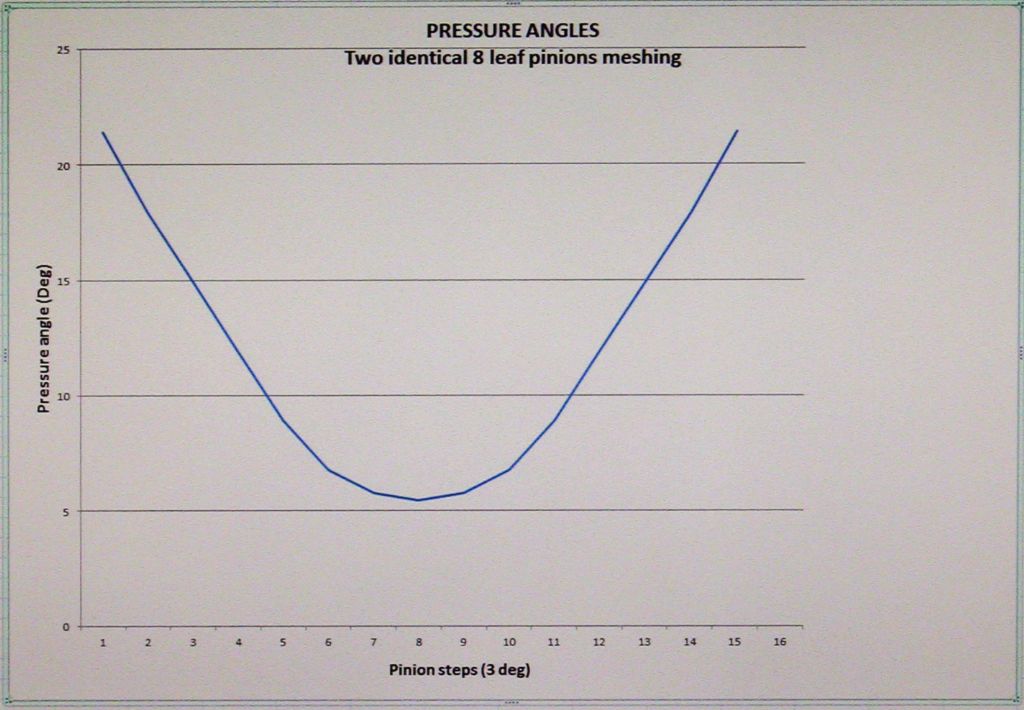
          Rotating meshed identical 8 leaf pinions through 45 degrees in steps of 3 degrees, the pressure angle plot is parabolic, symmetrical about the vertical centre line, and dipping from about 22 degrees to 5.5 degrees (and back again).

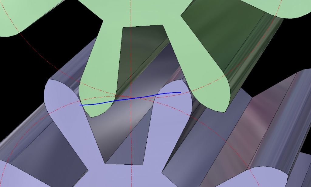
          The trace of the line of contact wobbles slightly, tracking at an average of about 13.7 degrees.

          As with previous results and following the BS 978:Part 2 design parameters, the 'wobble' results from the radius of one tooth contacting the flank of the opposing tooth for at least 50% of the trace.

          Although I can't see where this could be useful, I'll prepare the results as before.

          Sam smile d

          #405293
          Bazyle
          Participant
            @bazyle

            Thanks Sam, I'm finding this interesting though my CAD skills don't go much beyond square blocks. I was basing my thought on the way it was bending towards the smaller gear, so I surmised that as you moved progressively to the other gear being smaller it would bend that way , therefore going through a 'zero'. But of course that wasn't allowing for different gear profiles.

            Rolling contact: Following link after link given so far I came to this one which has a brief mention of cycloidal form and indicates that it is achievable with true cycloids but actually making them is the problem, so everyone just approximates and lives with it.

            #405392
            Michael Gilligan
            Participant
              @michaelgilligan61133
              Posted by Bazyle on 16/04/2019 11:38:24:

              … Following link after link given so far I came to this one which has a brief mention of cycloidal form and indicates that it is achievable with true cycloids but actually making them is the problem, so everyone just approximates and lives with it.

              .

              Hopefully, you followed the links within that, and eventually reached this page: **LINK**

              http://www.hessmer.org/gears/CycloidalGearBuilder.html

              … which is a very fine piece of work.

              MichaelG.

              #405402
              Sam Stones
              Participant
                @samstones42903

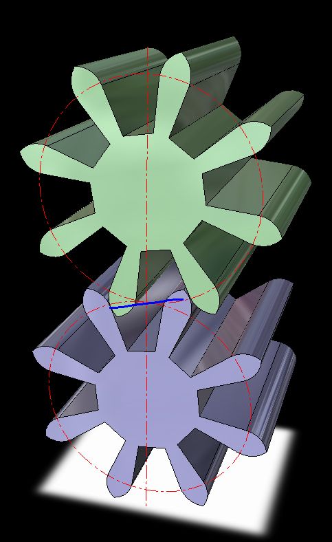
                From your question Bazyle, here are two identical ‘gears’ in mesh.

                two---8-leaf-pinions-meshing.jpg

                I chose to use the 8-leaf pinions as a simple and quicker method to get the results. When I was doing the 290-tooth wheel meshing with the 8-leaf pinion, it was quite laborious ‘chasing’ a pinion tooth with a wheel tooth. There’s nothing in my CAD package that allows any sort of dynamic interaction.

                This close-up shows the contact trace, a slightly wobbly blue line at an angle of about 13.7 degrees.

                two---8-leaf-pinions-meshing---cu.jpg

                I have to confess that in view of the symmetry and a somewhat lazy attitude, I flipped (mirrored) a half-trace (left to right and top to bottom).

                Here's the plot of the pressure angle, also featuring the mirrored data.

                img_0650 - 8-8 - meshing pinions.jpg

                I couldn't bring myself to reduce the depth and plot each one as I did for the 290-8 and 198-7 pairs.

                Sam smile d

                #405962
                Sam Stones
                Participant
                  @samstones42903

                  This thread was becoming such a mesh, that I decided to deal with the lantern pinion issue (suggested earlier) under another title.

                  Once it's loaded, I'll leave a link on this thread.

                  Sam smile d

                  #406111
                  Sam Stones
                  Participant
                    @samstones42903

                    Here are the links …

                    Part A

                    **LINK**

                    Part B

                    **LINK**

                    Phew!!!

                    Sam smile d

                  Viewing 8 posts - 26 through 33 (of 33 total)
                  • Please log in to reply to this topic. Registering is free and easy using the links on the menu at the top of this page.

                  Advert

                  Latest Replies

                  Viewing 25 topics - 1 through 25 (of 25 total)
                  Viewing 25 topics - 1 through 25 (of 25 total)

                  View full reply list.

                  Advert

                  Newsletter Sign-up