Worm and Worm Gear Design and Manufacture

Advert

Worm and Worm Gear Design and Manufacture

Home Forums Workshop Techniques Worm and Worm Gear Design and Manufacture

Viewing 17 posts - 26 through 42 (of 42 total)
  • Author
    Posts
  • #132067
    Mark C
    Participant
      @markc

      Bazyle,

      Perhaps it might be of interest to make a new thread with a short "how to" with pictures? The pictures would be specific to SW but the process would be generic to most 3D cad systems.

      Mark

      Advert
      #132216
      Anonymous

        Mark: Many thanks for posting the picture of the worm wheel, it looks really impressive. However, of course I have a 'yes but', but I'll continue that in the other thread that has been started specifically on the drawing of the worm wheel.

        Bazyle: The pitch of my worm is rational, ie, can be expressed as p/q, where both p & q are integers. In my case it is 0.5" or 1/2. The DP of a gear is the number of teeth on a gear with a pitch circle diameter of 1". However, the circumference of a PCD of 1" is pi inches. Pi is an irrational number, ie, there are no values of p or q for which pi=p/q. The pitch of 0.5" does not neatly divide into the circumference, and it makes no sense to have a partial tooth, so the DP must be irrational. Normally it is the other way round. The gear has an integer value of DP, so if you expand the gear to make a rack, the pitch of the rack, or mating worm, will not be rational, but an irrational value. On my lathe, with a change of one gear in the gear train, it is possible to cut an approximation to these irrational numbers, so that worms could be screwcut to fit gears with integer values of DP. In essence the gear train is creating an approximation for pi.

        Regards,

        Andrew

        #132586
        Anonymous

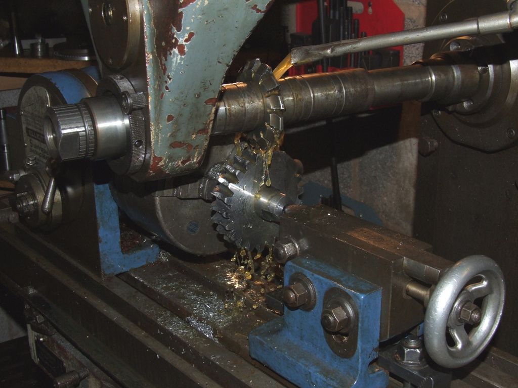
          I had a go at free hobbing a worm wheel today. A blank was hogged out of a lump of hot rolled flat bar, 'cause I've got loads of it and didn't have an aluminium blank of the correct size. The first milling operation is to gash each tooth. Ideally one uses an involute cutter of the correct DP, the right number of teeth, and the same diameter as the worm. I had a 6DP involute cutter for 21-25 teeth, which is close, but it's much larger diameter than the worm. A quick sketch in my CAD system gave me the maximum depth of cut without over cutting at the edges, which was about 89 thou less than the full depth. For gashing the mill table is set over at the lead angle of the worm (make sure you set it in the right direction wink) and the gashing cut is straight down. Here's the gashing set up:

          worm wheel gashing.jpg

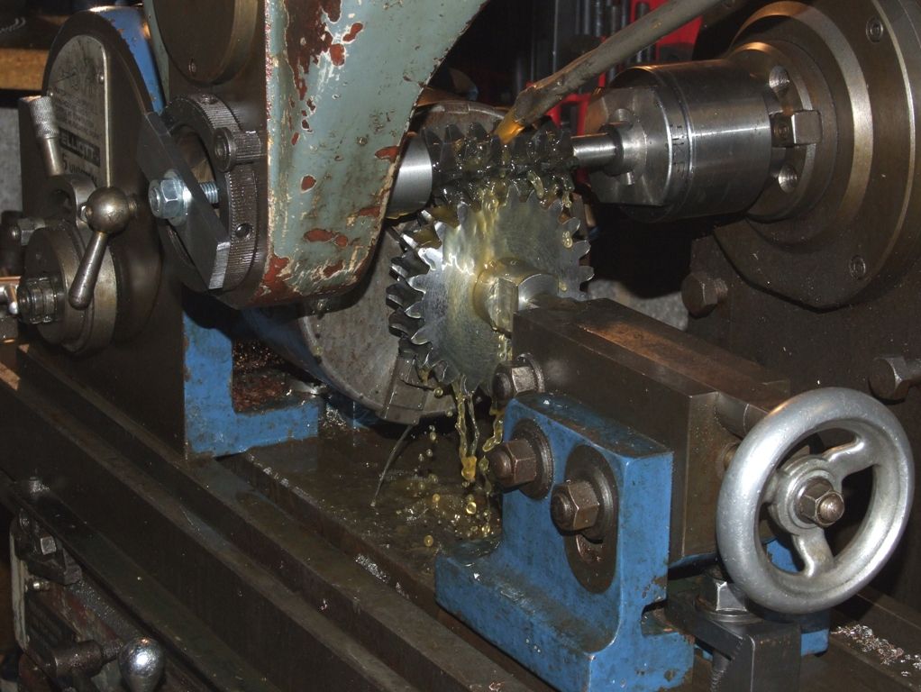
          For free hobbing the table is set back square and the arbor on which the worm wheel is mounted fitted with spacers to allow the worm wheel to rotate freely. Since I hadn't been able to gash to the full depth I was a bit worried that the hob wouldn't engage and drive the worm wheel properly. I needn't have worried. I calculated that the full depth of cut was 11.75mm, and I was able to wind the hob in by 10mm before it started cutting. My horizontal mill has a clutch, which is really useful for tip-toeing up to the cut, allowing the hob to rotate, but slipping the clutch if there's a dig in. In the event the whole thing was a non-event. Here's a picture of the hob in action:

          worm wheel hobbing.jpg

          Note the bodged support for the outer end of the hob, utilising a piece of steel clamped into the over arm support. The hob cut smoothly with no vibration or noise, despite the somewhat iffy, ie, non-existant, relief on the teeth. I cut to the required depth using the machine dials, and was pleased to see that the witness marks from the gashing just disappeared, which means I got my maths right for the various depths of cut.

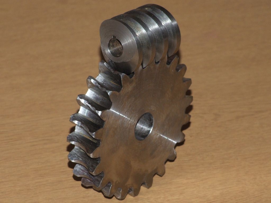
          Here's the worm wheel and worm:

          worm and worm wheel.jpg

          This evening I roughed out the cast iron blanks for the real worm wheels on the traction engine. I hope that they will cut a bit better than the hot rolled, which tends to 'smear' somewhat. Still, the worm and worm wheel mesh together smoothly. Overall I am happy with my first attempt at free hobbing with my home made hob.

          Regards,

          Andrew

          PS: And I even had time to take short videos of the gashing and hobbing processes.

          #132652
          Sub Mandrel
          Participant
            @submandrel

            >applause<

            neil

            #132666
            JasonB
            Moderator
              @jasonb

              Looks good Andrew, do you think that the slightly rough finish to the wheel creasts is due to the teeth on the hob only going down as far as the root? and its rubbing away that part rather than cutting.

              J

              #132699
              Anonymous

                Jason: I was concerned that the hob wouldn't cut that well in hot rolled, as it has zero rake, and my experience of hot rolled is that it tends to 'smear' if the tools aren't sharp with positive rake. However, having had a close look under a magnifying glass I don't think that the hob was the basic problem on the throat of the worm wheel. As designed there should be a 25 thou gap between the throat of the worm wheel and the core diameter of the worm, and hob. But it looks like I didn't quite get the hob centred over the worm wheel, so at maximum depth of cut the core of the hob has contacted the throat of the worm wheel on one side and smeared some of it over a portion of the throat. Carelessness on my part, and being in a hurry to see if the hob would actually work, or if the whole experiment would end up in discombobulation.

                This is where the theory and practice diverge. The books glibly say centre the cutters (involute for gashing and the hob) over the blank and commence cutting. But they don't tell you how to centre the b***y cutters! I should have made a better job of centring the hob, but the involute cutter for gashing is more of a problem. The instructions say centre the cutter in both X and Y over the blank and then swivel the table. But the cutter will only stay centred if the blank is exactly over the point where the table swivels? So I swivelled the table first and then attempted to centre the involute cutter. In the Y direction, at right angles to the worm wheel axis, I used the trapped ruler method, which I think is probably good enough. However, in X, aligned with the worm wheel axis, I winged it by estimating when the cutter was just nicking each side of the throat and took that as the centre. I suspect that the throat wasn't precise either, cut by hand feeding a button insert tool followed by a file. All rather crude, but not really the main purpose of the experiment. The main purpose was to test whether I could make a home made hob that would then free hob a worm wheel. From that point of view I think the experiment was successful.

                However, when I make the real worm wheels in cast iron there are a number of secondary things that I need to pay more attention to:

                1: Ensure that the throat is properly dimensioned and is central on the blank – possibly by making a measurement jig, or a form tool.

                2: Take more care to centralise the gashing cutter in X and Y

                3: Take more care to centralise the hob in X

                As an aside one can see an number of 'facets' on each of the teeth. I assume this is where the individual teeth of the hob have taken a cut, more teeth would give a smoother finish, but result in weaker teeth.

                Regards,

                Andrew

                PS: I plan to bring all, or some, of the worm and worm wheel experiments to the next SCMTEG meeting.

                #132706
                Mark C
                Participant
                  @markc

                  Andrew, Had you cut your teeth in a spiral with one full tooth pitch being less than the spiral angle you might have solved your facet problem but it would have also required the hob to move axially by one full "hob tooth" pitch so that with many turns of the hob and wheel and very small axial increments, you would come close to cutting as if there were no gaps between the hob teeth. At the moment, the hob having gaps between it's teeth (and the gaps being aligned) results in the hob effectively being missing a section at the same place each time. Things may also work even with straight hob tooth alignment as long as the hob is moved axially but I need to think about that!

                  Mark (who never got taught this much detail about worm wheel transmission when he was taught design – perhaps I can claim compensation?)

                  No, I think you need spiral teeth as straight teeth will never change their relative position to the wheel even if you move the hob – think in terms of the hob rolling around a stationary worm wheel….

                  Edited By Mark C on 15/10/2013 01:29:26

                  #132766
                  Anonymous

                    Mark: I'm not sure I follow your argument? The teeth on the hob are cut on a spiral, in fact an exact replica of the helix on the worm. Or are you saying I should have cut the flutes between the teeth on a spiral?

                    There is no common factor between the number of teeth on the hob (7) and the teeth on the worm wheel (22), so I assume that a give tooth on the hob will only mate with the same tooth on the worm wheel every 7×22 times. Although, if we assume every tooth is identical, the facets on the worm wheel teeth will be the same.

                    I think that if I move back and forth in the Y axis then I can reduce the facet effect. If I move the Y axis exactly 0.5", ie, the pitch of the worm then I don't change anything, but if I move, say, half that amount, then as each tooth comes into contact with the worm wheel it will be in a slightly different position?

                    Regards,

                    Andrew

                    #132770
                    Mark C
                    Participant
                      @markc

                      Andrew, yes, I meant the flutes ( I was thinking teeth at the time). The problem comes from the gaps between the cutting edges of the teeth along the helical worm tooth path, it will always be the same relative to the worm wheel and consequently, the facets will form as they will bridge the gap between the cutting edges on the wheel. Sorry if that is confusing but it is getting hard to describe without pictures (which are easy – well, fairly easy – to conjure in my minds eye but not so easy to create on the screen).

                      Mark

                      Sorry, to continue your points; the hob may have 7 radial teeth (6 flutes) but the relationship is between the worm form and the wheel which is obviously 1:22 I.E. one rev of the worm advances the wheel by one pitch (or tooth) so the facets form between the passing tooth flutes. Advancing the hob forward and back along it's axis will improve the faceting but to eliminate it I think you have to both advance/retard the hob and also cut helical flutes such that the flute helix bridges the helical distance between hob teeth (cutting edges) over the distance moved axially.

                      Edited By Mark C on 15/10/2013 21:55:14

                      #132865
                      Anonymous

                        Mark: Thanks, I think I understand now. I could have cut the flutes on a helix, but obviously straight is more straightforward. laugh By the way 7 teeth means there are 7 flutes. Even as it stands one has to have the light in the right place to see the faceting, so from a practical point of view I'll probably just move the worm wheel relative to the hob a little bit when I cut the real worm wheels. I might try it on my test piece first though, just in case!

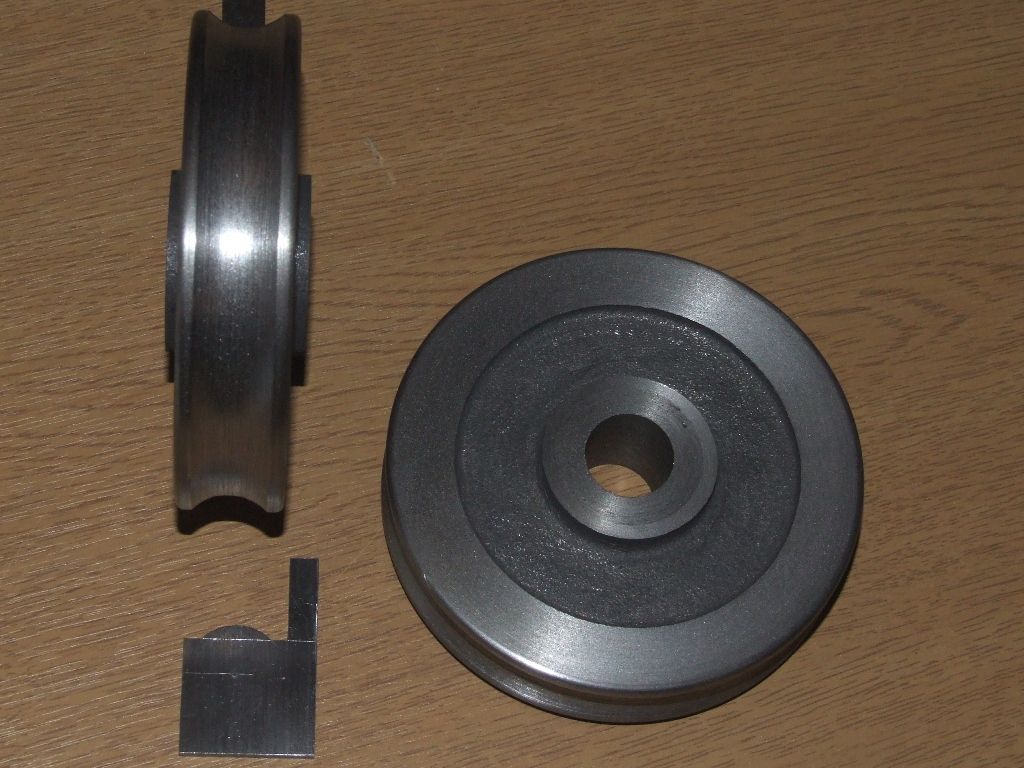
                        More progress, I've marked out and filed a template for the worm wheel throat from steel sheet, and finished the cast iron blanks for the final worm wheels:

                        worm wheel blanks.jpg

                        Regards,

                        Andrew

                        #132868
                        Mark C
                        Participant
                          @markc

                          Oops! I did say I could see it in my minds eye – didn't say anything about being able to count in there though, that would require multitasking…

                          On a more serious note, it is easy to get hung up on details for details sake – material, surface finish, precision of form mater significantly on a heavily loaded or positioning worm and wheel but for a cast gear on a model it's going to get hard to measure the errors in most home workshops.

                          Mark

                          #132911
                          Sub Mandrel
                          Participant
                            @submandrel

                            Hi Andrew,

                            If you can angle the blank and keep the hob in line with one of the machine axes, you can move it back and forth along that axis while it is cutting, or just once it has reached full depth. A slow enough traverse of just one tooth pitch should be enough to eliminate any and all facets.

                            Neil

                            #132920
                            Bazyle
                            Participant
                              @bazyle

                              I think you should write this up for MEW ensuring that you use the word 'discomhobulaton' and not allow them to spellchange it so that it will have precedent as a real word when used correctly in this context.

                              #132937
                              Anonymous

                                Mark: Agreed, I think I've reached the point where I'm just going to make the worm wheels and then move onto the next part. I quite fancy having a go at the crankshafts, now I've sorted out cutting the splines. I've also got some experiments to do as a precursor to having a go at making my own pressure gauges.

                                Stub: Precisely, while the milling machine table is set over at the lead angle of the worm for gashing, when using the hob everything is set orthogonal. So it'll be easy to move the Y axis, and hence the relative position of the hob, to reduce the faceting. I would expect that a couple of traverses at full depth will be fine, anything before that will just be cut away.

                                Bazyle: I love the word play, wish I'd thought of it! However, I'm not planning to write up the experiments for MEW.

                                Regards,

                                Andrew

                                #135140
                                Anonymous

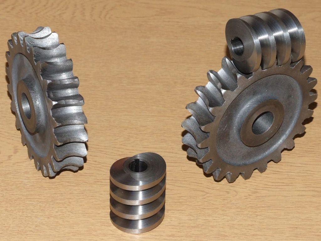
                                  Yesterday, while the CNC mill was whirring away cutting the teeth on a bevel gear, I gashed and free hobbed the real worm wheels for my traction engine steering gear. To save space I haven't posted pictures of the gashing and hobbing processes, as they're not much different to the earlier tests; minus the coolant though as the real parts are cast iron. Here are the machined worms and worm wheels:

                                  worms and worm gears.jpg

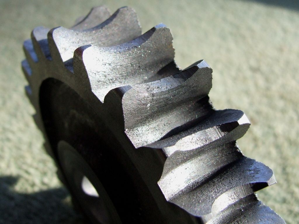
                                  I made a few changes from the procedure used to make the test worm wheel. When gashing I didn't cut quite so deep, 9mm instead of 9.5mm, the idea being that the hob would give a better looking result if it had to remove a little more from the bottom of the tooth spaces. I also took more care to centralise the hob before cutting. The main change was after hobbing to full depth; I upp'd the spindle speed, to 117rpm, and wound the cross axis over about 1/2" in small steps in an attempt to get rid of the faceting on the worm wheel teeth due to the straight flutes on the hob. Here's a close up of the worm wheel teeth, warts and all:

                                  worm detail.jpg

                                  The picture was taken straight after machining, I need to do a bit of deburring and cleaning up. The finish isn't quite as bad as the picture suggests, but importantly the faceting seen on the test worm wheel has disappeared.

                                  The parts are not perfect sad, but I've learnt a lot, had some fun, and it's now time to move onto other items.

                                  Regards,

                                  Andrew

                                  #135147
                                  John McNamara
                                  Participant
                                    @johnmcnamara74883

                                    Thanks Mark for the tip re drawing a worm gear.

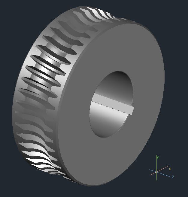
                                    This one was drawn with AutoCAD as a solid model. it was drawn freehand the geometry is just a guess. Now I will have tor try to get my head around designing proper worm wheels.

                                    Regards
                                    John .

                                    worm gear with autocad.jpg

                                    #135182
                                    Stovepipe
                                    Participant
                                      @stovepipe

                                      Reading this thread, I was hanging on for dear life, but I think I broadly understand what was going on. Thanks Andrew, and all the other contributors, for the enlightenment and detailed explanations. Now back to my knitting.

                                      Dennis

                                    Viewing 17 posts - 26 through 42 (of 42 total)
                                    • Please log in to reply to this topic. Registering is free and easy using the links on the menu at the top of this page.

                                    Advert

                                    Latest Replies

                                    Home Forums Workshop Techniques Topics

                                    Viewing 25 topics - 1 through 25 (of 25 total)
                                    Viewing 25 topics - 1 through 25 (of 25 total)

                                    View full reply list.

                                    Advert

                                    Newsletter Sign-up