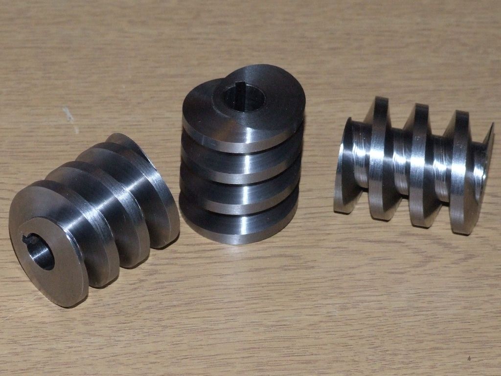
Rather than clutter up the 'What did you do today?' thread I've started this thread to discuss the design and machining of a worm and worm gear for the steering gear on a 4" scale traction engine.
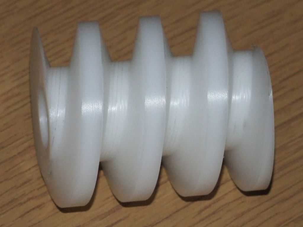
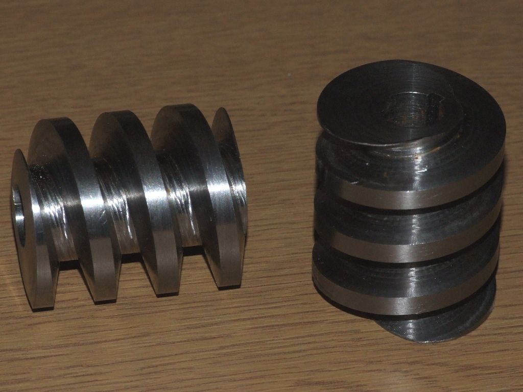
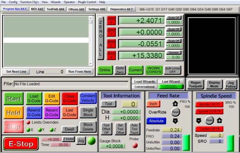
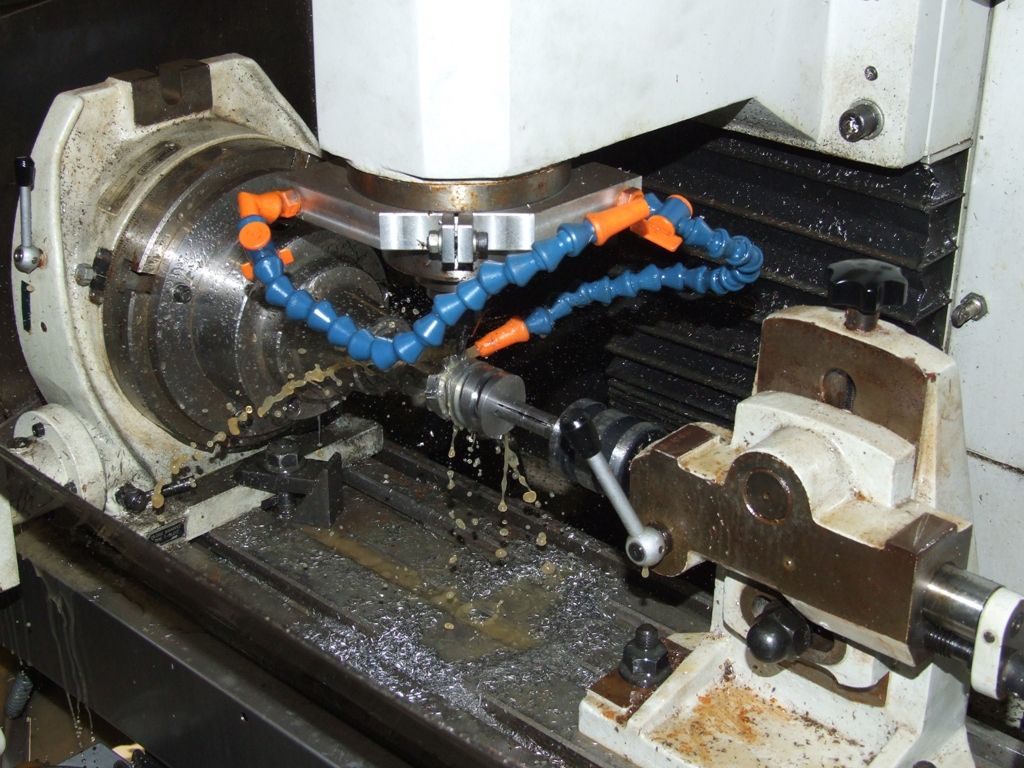
The drawings call for a 2 start worm with a pitch of 1/2" and an OD of 1.48", plus a quoted lead angle. There is no detail about the thread form, depth or anything else, and the lead angle quoted is wrong. The thread form is diagrammatically shown as Acme, which seems reasonable. My lathe will cut 2tpi, but not the 1tpi as required for the two starts. That left me with two choices for cutting the worm. One, use the vertical mill and a series of ever smaller cutters while driving the dividing head from the table to get the helix. Two, use the vertical head on the horizontal mill with an involute style cutter to cut the thread in one pass, again driving the dividing head from the table. I don't have the requisite 'involute' cutter, so step by step it is. In which case I might as well do it on the CNC mill, as it's less effort. My CAM program can only do 4th axis toolpaths parallel to the rotary axis, or round and round it. Neither is satisfactory; the ideal would be to follow the helix of the worm. So I hand wrote my own G-code, which turned out to be quite simple, just a series of G01 moves with arguments in X and A. At this juncture it was pointed out that a 2-start worm is wrong, as the front wheels will back drive the worm gear assembly.  So I re-designed the worm as a single start. I could have cut this on the lathe, but since I was so advanced with the G-code I decided to stick with the CNC mill. I won't go into the details of the thread form, but I did change the included angle of the Acme form to 30°, rather than the more common 29°, as I could buy a 30° tapered endmill. The basic code and methodology seems to work well, the next task is to cut the worms in steel, rather than plastic like this:

I'll also get the hand correct, the worm is supposed to be RH, but the plastic demo is LH.
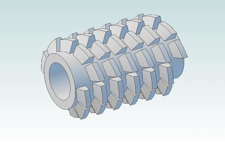
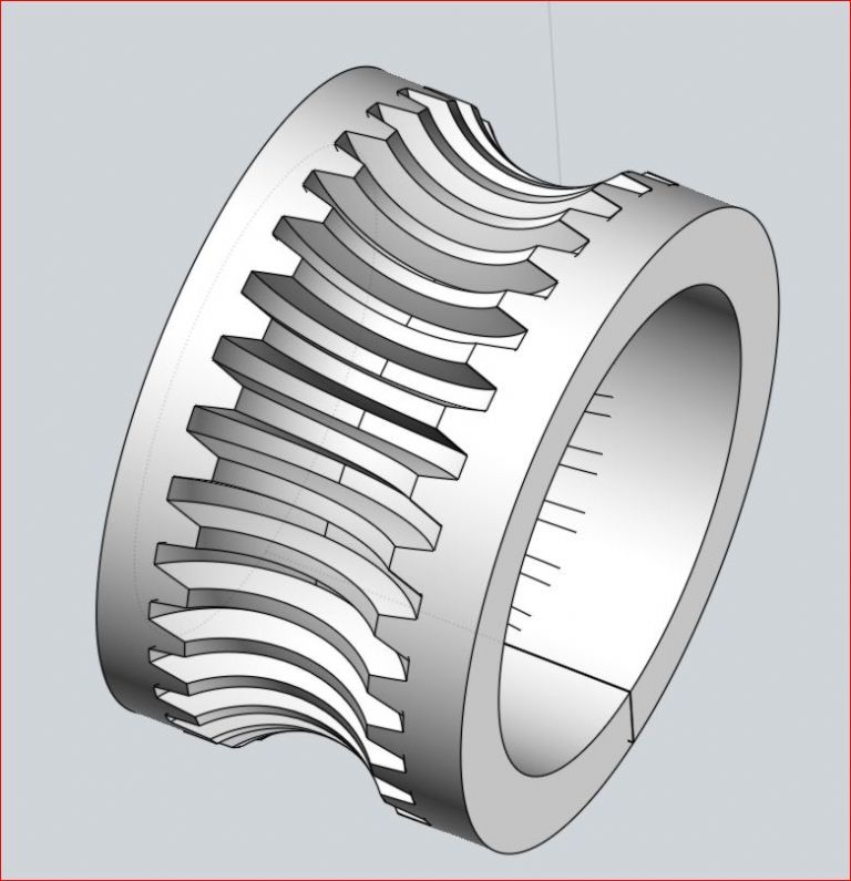
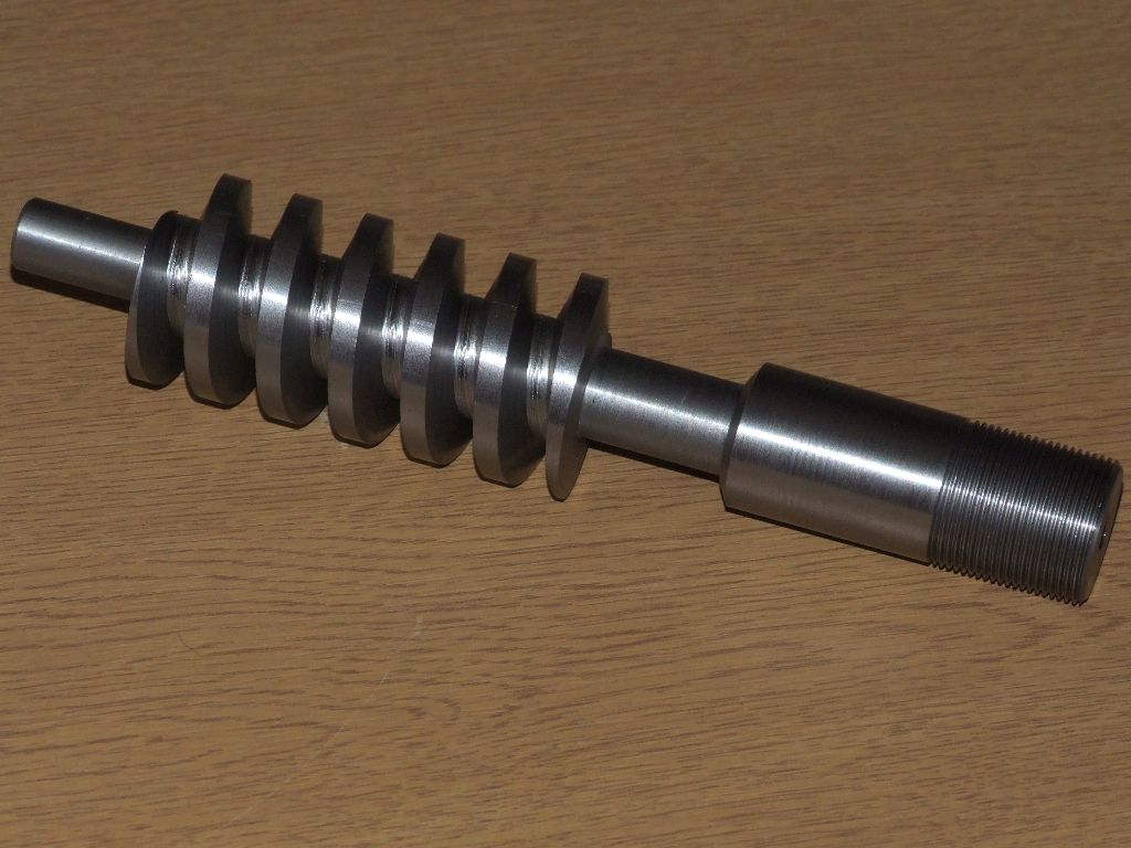
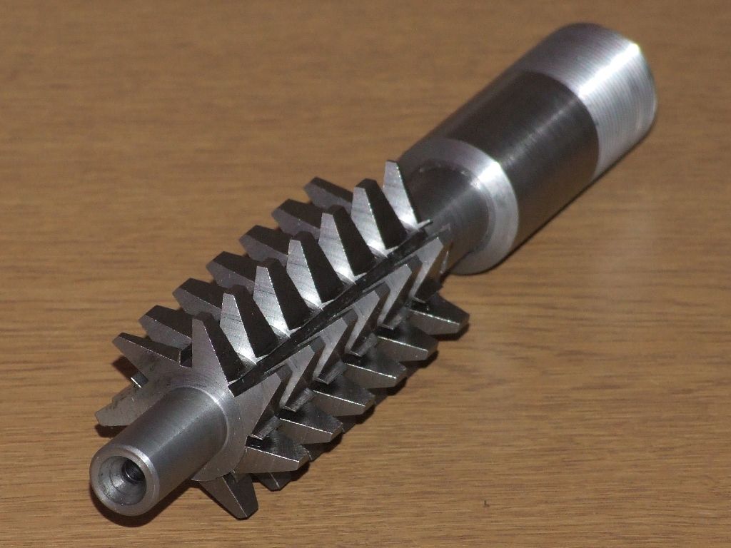
For the worm wheel the drawings show what is essentially a helical gear. Since the pitch of the worm is rational the DP of the mating worm wheel is irrational, so involute cutters will not be available. Furthermore I wanted a single enveloping worm wheel, not a helical gear. The obvious way to make this is by free hobbing, ie, the hob drives the worm gear as it is cut. I've spent a lot of time looking at hob design and drawing various styles of hob, like this:

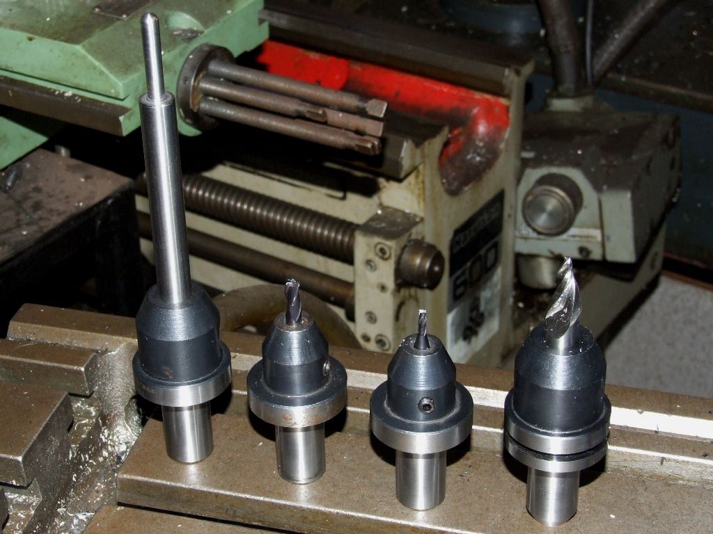
However, I've decided that it is just too involved to make a hob with the proper form relief. I also looked at machining the worm wheel direct on the CNC mill. However, the tooth form required is very complex, and I miserably failed to draw even a rough approximation. So back to free hobbing it is. For the hob I am going to essentially machine a worm in silver steel, which can be gashed to provide some measure of relief, and then hardened and tempered. I intend to add extensions to the hob so that one end will fit into a Clarkson Autolock chuck and the other end can be supported by a centre.
As I make progress I'll update this thread.
Regards,
Andrew
Stovepipe.


