WM18 – Z Axis power feed

Advert

WM18 – Z Axis power feed

Home Forums General Questions WM18 – Z Axis power feed

Viewing 25 posts - 26 through 50 (of 68 total)
  • Author
    Posts
  • #420708
    petro1head
    Participant
      @petro1head
      Posted by JasonB on 23/07/2019 21:00:58:

      My x feed has a gear head motor and I can turn the handle with that still engaged but easier to knock the dog clutch out of engagement.

      The Sieg machines really only use the feed to save you cranking the high up handle for general positioning of the head and use the quill fine feed to put on a cut so don't give you a Z handle.

      Is this somit you made yourself? Any chance of some photos please

      Advert
      #421572
      petro1head
      Participant
        @petro1head

        Looking at the top of the mill the lead screw comes through a bearing with a threaded portion and two thin nuts that lock together.

        What would be the best way to attach the motor motor?

        it i use some sort of clutch does anyone have a simple setup/drawing 

        Edited By petro1head on 30/07/2019 06:21:46

        #421671
        petro1head
        Participant
          @petro1head

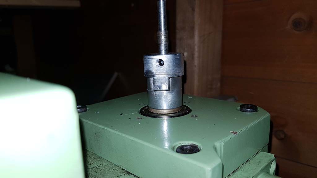
          So I think I am nearly there.

          This is how I am going to connect the stepper motor to the mill

          wm18 project 1.jpg

          I am going to buy this stepper motor, as reccomended by Chris, thanks – Link

          This for the power supply – Link

          This PWM controller – Link

          Up/Down Switch – Link

          Will also need a on/off switch and a box to house everything, except the power supply which will be in a separate box.


          Edited By petro1head on 30/07/2019 14:02:03

          #421688
          ChrisB
          Participant
            @chrisb35596

            You should be fine with those components. I have the exact same things plus some more buttons for my power feed on the X-axis.

            #421692
            petro1head
            Participant
              @petro1head

              Oh forgot I will need a stop pluger so I dont go too far.

              I have a single unit on my X axis with a pluger either side but cant seem to find them

              #421704
              not done it yet
              Participant
                @notdoneityet
                Posted by petro1head on 30/07/2019 16:37:49:

                Oh forgot I will need a stop pluger so I dont go too far.

                I have a single unit on my X axis with a pluger either side but cant seem to find them

                Is ‘pluger’ a tyneside term? Never heard of it. Do you mean a limit switch?

                #421744
                petro1head
                Participant
                  @petro1head

                  Yeh, thats the badger

                  #422552
                  petro1head
                  Participant
                    @petro1head

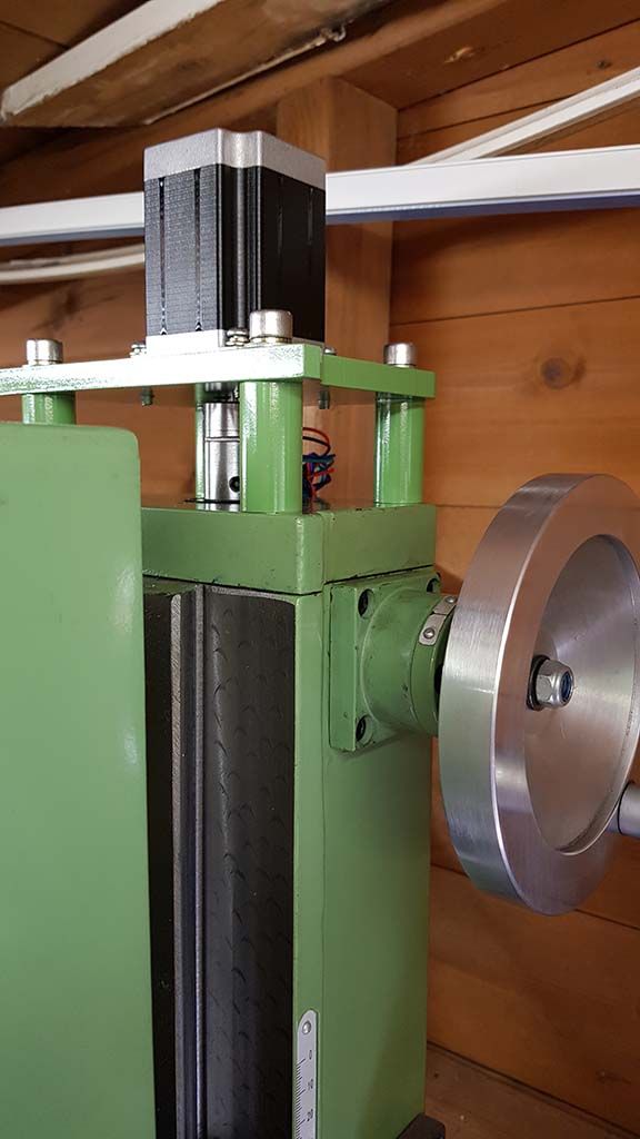
                    Work has started, got the mount, connection and motor installed

                    z axis 2.jpg

                    Just waiting for delivery of the PWM and project boxes then I can start the wiring.

                    Next task while waiting id to fit the limit switched.

                    Re the wiring would it be worth covering the wire metal conduit  What size and where from? Or I could use this stuff Link

                    The motor only put a small amount of resistance on the handle so happy

                    Edited By petro1head on 04/08/2019 13:27:29

                    #422573
                    Enough!
                    Participant
                      @enough

                      It's not very clear to me whether the intention is as a z-axis feed while cutting or simply to raise/lower the head without effort.

                      If it's the latter, the poor-man's version is a socket fitted in an electric drill/driver with the clutch set appropriately.

                      #422575
                      petro1head
                      Participant
                        @petro1head
                        Posted by Bandersnatch on 04/08/2019 17:10:04:

                        It's not very clear to me whether the intention is as a z-axis feed while cutting or simply to raise/lower the head without effort.

                        If it's the latter, the poor-man's version is a socket fitted in an electric drill/driver with the clutch set appropriately.

                        Currently my thought are just to raise lower the head however once done it may well be good enough to feed while cutting.

                        re your second statement, will, yes i could just do that. Bit Heath Robinson but each to their own.

                        for me its also the enjoyment of the project

                        #422585
                        Enough!
                        Participant
                          @enough

                          … Oh, sure – whatever lights your candle of course. Wasn't detracting from what you're doing.

                          #422868
                          petro1head
                          Participant
                            @petro1head

                            Oh bugger!

                            The stepper motor ChrisB linked to does not seem powerfull enough and cant turn the lead screw

                            Edit:  The current switches were set to the lowest current.  However as the head raises it get a little tighter and the motor then struggles, currently looking into why it gets tighter

                            Edited By petro1head on 06/08/2019 14:00:06

                            #422873
                            Joseph Noci 1
                            Participant
                              @josephnoci1

                              Bit late to enter the fray, but…I do think a NEMA34 size would have been better, or at least a motor with maybe around 3 to 4NM torque. The problem is really overcoming the stiction in the system and will be worse on the up..

                              If you are willing to try a few things –

                              Does the motor turn on its own, disconnected from the leadscrew?

                              If so, loosen up the Z Gibs completely and try again, just to see if things move.

                              If not, let me know and we take it from there.

                              Do you have an oscilloscope?

                              Can you post a wiring diagram of how you connected the bits?

                              Joe

                              #422876
                              ChrisB
                              Participant
                                @chrisb35596

                                If you got the NEMA23 like the one I linked, with a holding torque of 1.9NM it's more than enough to move the column on a WM18.

                                I have tested mine on the X axis and it moves the table effortlessly. Make sure it's wired correctly, there are a lot of settings on the stepper controller. As I mentioned in my post above. I didn't wire it myself as I'm not electrically minded but I recall it was a bit of a fiddle until we got it set properly. I'll ask my brother for a wiring diagram and controller settings.

                                Have a look at the below video, he's using a 3NM, Nema23 for the table powerfeed on a Raglan.

                                **LINK**

                                Edited By ChrisB on 06/08/2019 14:07:15

                                #422879
                                petro1head
                                Participant
                                  @petro1head
                                  Posted by Joseph Noci 1 on 06/08/2019 13:39:43:

                                  Bit late to enter the fray, but…I do think a NEMA34 size would have been better, or at least a motor with maybe around 3 to 4NM torque. The problem is really overcoming the stiction in the system and will be worse on the up..

                                  If you are willing to try a few things –

                                  Does the motor turn on its own, disconnected from the leadscrew?

                                  If so, loosen up the Z Gibs completely and try again, just to see if things move.

                                  If not, let me know and we take it from there.

                                  Do you have an oscilloscope?

                                  Can you post a wiring diagram of how you connected the bits?

                                  Joe

                                  I am starting to feel the 3nm motor may have been better Link

                                  Before fitting I bench tested the motor and it was turning fine.

                                  When I first fitted it the dip switches were set to 1 amp, when I set it to the required amperage, 2.8, it stated working on the mill.

                                  I don't have an occiliscpoe

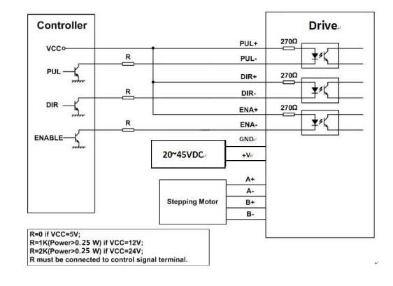
                                  Wiring diagram:

                                  stepper wiring.jpg

                                  #422881
                                  petro1head
                                  Participant
                                    @petro1head
                                    Posted by ChrisB on 06/08/2019 13:57:15:

                                    If you got the NEMA23 like the one I linked, with a holding torque of 1.9NM it's more than enough to move the column on a WM18.

                                    I have tested mine on the X axis and it moves the table effortlessly. Make sure it's wired correctly, there are a lot of settings on the stepper controller. As I mentioned in my post above. I didn't wire it myself as I'm not electrically minded but I recall it was a bit of a fiddle until we got it set properly. I'll ask my brother for a wiring diagram and controller settings.

                                    Have a look at the below video, he's using a 3NM, Nema23 for the table powerfeed on a Raglan.

                                    **LINK**

                                    Edited By ChrisB on 06/08/2019 14:07:15

                                    That was the YouTube vid I followed, however he is used the 3nm motor.

                                    I also wonder, the X axis is a lot easier to feed that the Z, concidering the weight of the head.

                                    Just a thought Chris

                                    Edited By petro1head on 06/08/2019 14:18:09

                                    #422883
                                    SillyOldDuffer
                                    Moderator
                                      @sillyoldduffer
                                      Posted by petro1head on 06/08/2019 13:17:46:

                                      Oh bugger!

                                      The stepper motor ChrisB linked to does not seem powerfull enough and cant turn the lead screw

                                      Edit: The current switches were set to the lowest current. However as the head raises it get a little tighter and the motor then struggles, currently looking into why it gets tighter

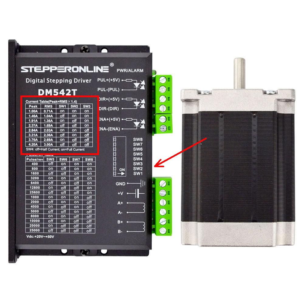
                                      I was going to suggest it might be the current settings. Stepper motors are current driven, more voltage has the potential to make them go faster but care then has to be taken to limit the current to keep the motor within operating temperature. The switch settings tell the controller to throttle the current to suit the size of motor connected.

                                      The Motor is rated 2.8A per phase so the controller should be operating at the high current end, I'd be tempted to try it on the maximum setting (3A RMS) :

                                      controller.jpg

                                      I put the arrow the image on before seeing PetrolHead's edit in case he hadn't spotted the DIP switches tucked away between the terminal blocks. He has…

                                      Dave

                                      #422884
                                      ChrisB
                                      Participant
                                        @chrisb35596
                                        Posted by petro1head on 06/08/2019 14:17:25:

                                        I also wonder, the X axis is a lot easier to feed that the Z, concidering the weight of the head.

                                        Thinking about it, that's true, the Z axis is a bit harder to move than the X axis – I must have wrongly assumed they required similar force. I'm sorry for misleading you.

                                        Did you manage to make it move with 2.8A?

                                        #422885
                                        petro1head
                                        Participant
                                          @petro1head

                                          At either 2.8a, 3.1 or 3.7 its truggles at the top end with the jibs loosened off.

                                          So I am going to see if they will swap the motor for me.

                                          I'll send you the bill Chris

                                          #422887
                                          Joseph Noci 1
                                          Participant
                                            @josephnoci1

                                            What do you mean by 'top end'? At high speed ( top end of) or top end of the column? Where on the column's height should make no difference, unless there is binding at the top and not lower down. You may need to do some setting up and move the axis only with the handwheel ( stepper mechanically disconnected) so you can feel if the movement is smooth up and down – I would suggest you try achieve that first, regardless of the torque of the chosen motor..

                                            That motor should be able to move the axis downwards with repeatable ease and if not, there must be some binding somewhere.

                                            The Oscilloscope – I would have liked to see the width of the step pulse from the PWM generator to the stepper driver – the driver normally requires a certain minimum width and nowhere can I find what the pulse width is of that PWM generator that you have. However, if this is a problem, it normally manifests as lost pulses, which may or may not be part of the problem you experience.

                                            A larger stepper needed , I think…

                                            Joe

                                            #422890
                                            ChrisB
                                            Participant
                                              @chrisb35596
                                              Posted by petro1head on 06/08/2019 14:38:16:

                                              At either 2.8a, 3.1 or 3.7 its truggles at the top end with the jibs loosened off.

                                              So I am going to see if they will swap the motor for me.

                                              I'll send you the bill Chris

                                              Oh no! Looking at your photo showing the stepper on the column and noticed it's a fair bit short compared to the one I have. Checked mine and it's a 3NM NEMA 23…I need to go hide for a while – I'm really sorry!

                                              Down in the workshop, I took a spring scale and measured the force required to move the handwheels on the Z and X axes. The Z axis requires 1.8kg force to break away and around 1.6kg force to rotate the wheel. The X axis on the other hand requires 0.8kg force to break away and around 0.6kg force to rotate the wheel.

                                              With a wheel radius of 5.5cm this gives a torque of 1Nm for the Z axis and 0.45Nm for the X axis. So in theory the 1.9Nm motor should work – but that's just the theory!

                                              #422893
                                              petro1head
                                              Participant
                                                @petro1head
                                                Posted by Joseph Noci 1 on 06/08/2019 14:51:44:

                                                What do you mean by 'top end'? At high speed ( top end of) or top end of the column? Where on the column's height should make no difference, unless there is binding at the top and not lower down. You may need to do some setting up and move the axis only with the handwheel ( stepper mechanically disconnected) so you can feel if the movement is smooth up and down – I would suggest you try achieve that first, regardless of the torque of the chosen motor..

                                                That motor should be able to move the axis downwards with repeatable ease and if not, there must be some binding somewhere.

                                                The Oscilloscope – I would have liked to see the width of the step pulse from the PWM generator to the stepper driver – the driver normally requires a certain minimum width and nowhere can I find what the pulse width is of that PWM generator that you have. However, if this is a problem, it normally manifests as lost pulses, which may or may not be part of the problem you experience.

                                                A larger stepper needed , I think…

                                                Joe

                                                Top end of the column :0

                                                Is this any help: Frequency: High: 5.8KHZ-127KHZ, Mid: 590HZ-15.8KHZ, Low: 82HZ-2.3KHZ

                                                #422894
                                                petro1head
                                                Participant
                                                  @petro1head
                                                  Posted by ChrisB on 06/08/2019 15:27:01:

                                                  Oh no! Looking at your photo showing the stepper on the column and noticed it's a fair bit short compared to the one I have. Checked mine and it's a 3NM NEMA 23…I need to go hide for a while – I'm really sorry!

                                                  Aggggggggggggggggggggggggggggggggggggggggggg, FFS!

                                                  You are in the dog house!

                                                  I cant send the motor back becuase I shortened the wires

                                                  #422897
                                                  SillyOldDuffer
                                                  Moderator
                                                    @sillyoldduffer

                                                    For sizing the motor, here's what it look to overcome stiction and lift my WM18's head:

                                                    dsc06149.jpg

                                                    A weight of 6.5kg suspended from the manual winding handle was necessary to get movement. The handle is 55mm from the axle. 6.5kg is approximately 64N.

                                                    T = 0.055m x 64N = 3.52Nm

                                                    The handle turns the screw via 1:1 gearing.

                                                    Th e measurement confirms the 1.9Nm motor recommended by Chris is too small and a 3 to 4Nm motor as recommended by Joe is in the right ball-park. Not sure how typical my WM18 is: certainly raising the head is hard work!  Given my figures a 4Nm motor would be needed for my WM18.

                                                    As my maths is awful, grateful for corrections…

                                                    Dave

                                                    Edited By SillyOldDuffer on 06/08/2019 16:25:33

                                                    #422900
                                                    not done it yet
                                                    Participant
                                                      @notdoneityet

                                                      Probably wrong, but not necessarily insurmountable. Might just need some extra balancing forces to reduce the effective weight of the head

                                                    Viewing 25 posts - 26 through 50 (of 68 total)
                                                    • Please log in to reply to this topic. Registering is free and easy using the links on the menu at the top of this page.

                                                    Advert

                                                    Latest Replies

                                                    Home Forums General Questions Topics

                                                    Viewing 25 topics - 1 through 25 (of 25 total)
                                                    Viewing 25 topics - 1 through 25 (of 25 total)

                                                    View full reply list.

                                                    Advert

                                                    Newsletter Sign-up