Wiring A Dewhurst Switch-Single Phase

Advert

Wiring A Dewhurst Switch-Single Phase

Home Forums Beginners questions Wiring A Dewhurst Switch-Single Phase

Viewing 13 posts - 1 through 13 (of 13 total)
  • Author
    Posts
  • #7769
    Grotto
    Participant
      @grotto
      Advert
      #201632
      Grotto
      Participant
        @grotto

        Further to my previous post (year or so ago)…

        I've had a good trawl on the net, and have found numerous pages showing how to do this, but I think I must lack the knowledge to understand.

        I'm replacing my 3 phase motor with a single phase (looked at getting 3 phase but way too expensive, 3 phase motor is not the correct type to run single phase).

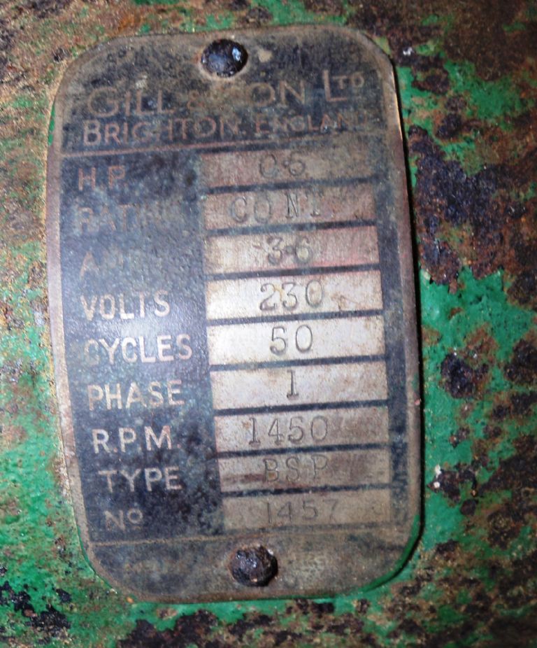
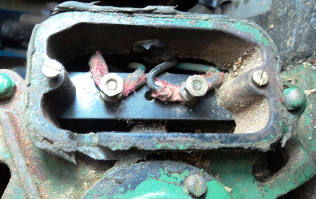
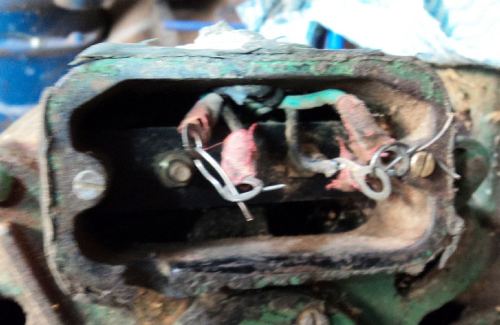
        I have a single phase motor (0.6 hp, type BSP) which only has two terminals.

        dsc06945.jpg

        dsc06946.jpg

        All the diagrams I've seen for wiring motor to Dewhurst have more terminals.

        Should I be separating the wires?

        Any help would be appreciated, as I even tried getting an electrician to sort it but he said he didn't know what to do.

        Thanks

        #201633
        Grotto
        Participant
          @grotto

          I'm wondering if it would be best to use a different (single phase) motor.

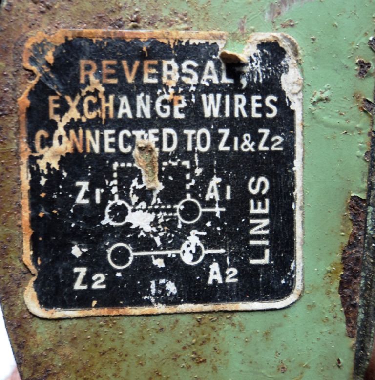
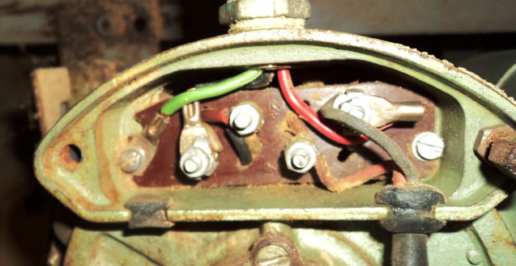
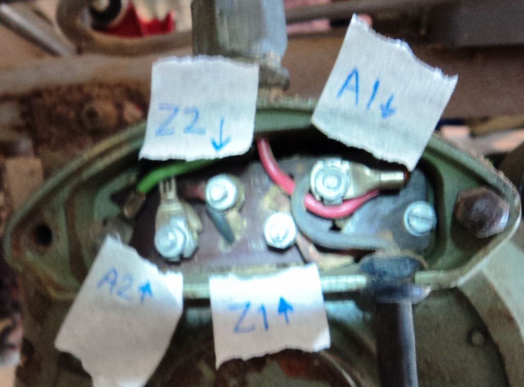
          I have a Gryphon on my bench saw which is 3/4 h.p. and has 4 terminals (A1, A2, Z1, Z2)

          dsc06947.jpgdsc06948.jpg

          It's capcitor start, but still not sure how to wire it as at present live and neutral (form power source) only go to 2 terminals

          #201641
          Les Jones 1
          Participant
            @lesjones1

            Hi Grotto,
            It will probably be possible to use a reversing switch with either of the motors. On the 0.6 HP motor two of the wires are probably the main winding and two the auxiliary winding. (Possibly via a centrifugal switch and start capacitor.) You would need to do some tests with a multimeter to work out which wires are the main winding. Does this motor have a start capacitor ? You would need to add a connector block so that the four wires (Plus the earth wire.) could be brought out to the reversing switch.
            on the 0.75 HP motor you would need to take a photograph of the connection box on the motor so that the labels on the terminals could be read. (Or add labels to the picture.) I am assuming this is a capacitor start motor and the cable from the bottom right hand side of the connector box goes to the capacitor.

            Les.

            #201657
            Robbo
            Participant
              @robbo

              It will be easier to use the Gryphon with the 4 terminals.

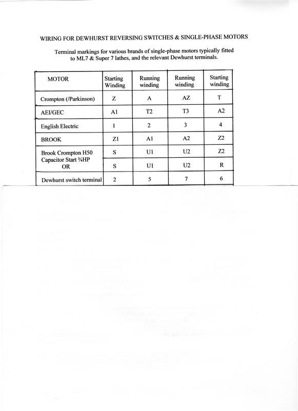
              This diagram may then help.

              fhp motor connections-003 (custom).jpg

              #201806
              Grotto
              Participant
                @grotto

                Thanks

                The Gryphon motor is 1.25 hp which seems a little grunty for an ML7, it 's also 2850 rpm which may (?) cause issues (not sure about this.

                The other motor (Gill & Son) is 1,450rpm which is what my 3 phase one was. I don't think it's capacitor start (no visible capcitor).

                I've undone the wires on the Gill motor and it looks like there is (just) enough length to attach them to a connector block.

                I have a multi meter, but am not sure how to test which are main winding & which are auxiliary. At present, one black and one green attach to each of the terminals (there are 2 green wires & 2 black).

                dsc06951.jpg

                On the Gryphon motor the capcitor wires (bottom right of photo) attach Black to A1, and Red to Z1. The power input wires attach Red to A1, and Black to A2.

                dsc06950.jpg

                #201832
                Les Jones 1
                Participant
                  @lesjones1

                  Hi Grotto,
                  I agree that the 1400 rpm motor is more suitable. The green wires will probably be one winding and the black the other winding. I would expect the resistance of the main winding will be between 5 and 10 ohms and the start winding between 10 and 20 ohms. (For connecting it up to the reversing switch it does not matter which is which.)

                  On the Dewhurst switch connect live and neutral VIA AN NVR SWITCH to terminals 1 and 3 (It does matter which way round.)
                  Connect the main winding to terminals 5 and 7
                  Connect the start winding to terminals 2 and 6

                  If forward and reverse are the wrong way round then swap over the wires on either terminals 5 and 7 OR 2 and 6 (BUT NOT BOTH)

                  Les.

                  Edited By Les Jones 1 on 25/08/2015 09:10:28

                  Edited By Les Jones 1 on 25/08/2015 09:15:27

                  #201849
                  Grotto
                  Participant
                    @grotto

                    Thanks Les, really appreciate the advice

                    the resistance of the black wires is around 3.8 ohms.

                    the green wires don't appear to form a circuit(?) as resistance doesn't read.

                    I'll have a better look in the morning

                    #201862
                    Les Jones 1
                    Participant
                      @lesjones1

                      Hi Grotto,
                      The black wires will be the main winding. The start winding is probably in series with the centrifugal switch (Which should be closed when the motor is stopped.) If the motor had a start capacitor that would also be in series with the start winding. So if there is a start capacitor you would not get a resistance reading between the green wires as a capacitor does not pass DC. If you are sure that the motor does not have a start capacitor then the centrifugal switch is faulty. (Or the start winding open circuit but this is unlikely.) You will need to dismantle the motor to get to the centrifugal switch to confirm that is the fault and if so repair it.

                      Les.

                      #202575
                      Grotto
                      Participant
                        @grotto

                        Had a go at pulling the 4 wires out, and wiring up.

                        worked forwards but looked like there was a fireworks display going on inside the motor.

                        reverse blew the trip switch.

                        I've put it back to standard and will just use the lathe without reverse until I get a more suitable motor.

                        thanks for the help, I'll be back!

                        #202587
                        J Hancock
                        Participant
                          @jhancock95746

                          You can do no better than buying the Model Engineer of 2nd November 1979.

                          The article REVERSING FRACTIONAL HORSE POWER MOTORS by R Jeffrey covers all of this in

                          'super simple ' detail.

                          #202589
                          J Hancock
                          Participant
                            @jhancock95746

                            You will also need to buy the Model Engineer of 7th March 1980 in order to see the three corrected

                            diagrams for the above !!!

                            #202594
                            Les Jones 1
                            Participant
                              @lesjones1

                              Hi Grotto,
                              If the motor works correctly when connected directly then it should work at least in the forward direction via the Dewhurst switch as in one direction it is connected exactly the same way. You have either wired it wrong or the Dewhurst switch is faulty.

                              Test the switch as follows. (With no other wires connected to the switch.)

                              With the switch in the off position.
                              Test for continuity between terminal 1 and the following terminals. 2, 3, 5, 6 , 7 There should be no continuity.
                              Test for continuity between terminal 3 and the following terminals. 2, 5, 6 , 7 There should be no continuity.

                              With the switch in the forward position.
                              Test for continuity between terminal 1 and the following terminals. 2, 3, 5, 6 , 7
                              You should get continuity to terminals 5 and 6 but NOT terminals 2, 3, 7
                              Test for continuity between terminal 3 and the following terminals. 2, 1, 5, 6 , 7
                              You should get continuity to terminals 2 and 7 but NOT terminals 1, 5, 6

                              With the switch in the reverse position.
                              Test for continuity between terminal 1 and the following terminals. 2, 3, 5, 6 , 7
                              You should get continuity to terminals 5 and 2 but NOT terminals 3, 6, 7
                              Test for continuity between terminal 3 and the following terminals. 2, 1, 5, 6 , 7
                              You should get continuity to terminals 6 and 7 but NOT terminals 1, 2, 5

                              (It is possible that the forward and reverse positions may the the wrong way round.)

                              Did you take the motor apart to check the centrifugal switch ? (To understand why you did not get ant continuity between the green wires.)

                              Les.

                            Viewing 13 posts - 1 through 13 (of 13 total)
                            • Please log in to reply to this topic. Registering is free and easy using the links on the menu at the top of this page.

                            Advert

                            Latest Replies

                            Home Forums Beginners questions Topics

                            Viewing 25 topics - 1 through 25 (of 25 total)
                            Viewing 25 topics - 1 through 25 (of 25 total)

                            View full reply list.

                            Advert

                            Newsletter Sign-up