Who labelled the X and Y axes for DROs on lathes and mills?

Advert

Who labelled the X and Y axes for DROs on lathes and mills?

Home Forums Workshop Tools and Tooling Who labelled the X and Y axes for DROs on lathes and mills?

Viewing 9 posts - 26 through 34 (of 34 total)
  • Author
    Posts
  • #631184
    Robin
    Participant
      @robin

      It's like trying to remember that the word data is plural. Always sounds wrong.

      On my lathe the DRO shows numbers for X and Z.

      If I want to zero Z, I press the button next to the Z value.

      If I want to set Z, I can press the Z button until the cows come home with no effect…

      I have to press the Y button instead.

      Whoever set it up didn't like the taste of XZ any more than I do. It just sounds icky sad

      best

      Robin

      Advert
      #631188
      Martin Kyte
      Participant
        @martinkyte99762
        Posted by John Haine on 28/01/2023 10:53:11:

        Posted by Martin Kyte on 27/01/2023 23:06:00:

        Not sure why that is confusing John, the controlled point that is the tip of the threading tool is rotating clockwise relative to the work.

        regards Martin

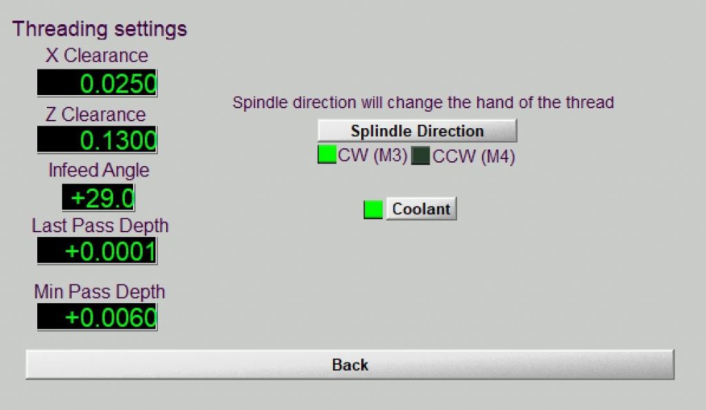
        Hmm. Well it got me puzzled the first time I threaded in M3 and I know others have been confused too from postings on M3 Support. One is used from milling to the CP being the centre of the rotating tool, the lathe is different. Part of the problem is that the M3 thread wizard isn't remarkably clear. This is "settings":

        m3_thread.jpg

        As a novice to Mach3, what "splindle" direction would you select for a RH thread? The correct answer is CW but for a lathe user that's reverse. Clearly the UI was designed by a software engineer.

        Yes, I can see your point. Once you add a layer of user interface on top you get a little more remote from the machine. I suppose I was just thinking about the machine itself and how I would label the axis and it does seem logical to me.
        regards Martin

        #631189
        Dave Halford
        Participant
          @davehalford22513

          I think it might be history.

          When you designed a DRO back in the day on paper, at a drawing board XYZ suited a Mill, graph layout for the table and the alphabet. Later when making a cheaper one for a lathe it looks a little silly to delete the centre display and also harder to take the circuitry out.

          #631190
          Circlip
          Participant
            @circlip

            My vernier clopolipper doesn't give a – – – –

            Regards Ian.

            #631191
            Martin Kyte
            Participant
              @martinkyte99762

              Does the CW/CCW question on the lathe have a parallel with the axis directions on the mill. With a mill the CP is the centre of the cutter in the spindle as John says. However as the table moves not the spindle the direction of travel is in the -X in order to create a +X CP movement.

              Similarly on the lathe with the CP at the tool tip which cannot rotate, in order to create a CW rotation of the CP the work (and thus the spindle) must rotate in the opposite direction which is CCW.

              regards Martin

              #631192
              Nicholas Farr
              Participant
                @nicholasfarr14254

                Hi John, I suppose that it all depends on one's understanding of the meaning of the words, for example, the start button for a lathe spindle is often stated as forwards and reverse, which doesn't really make sense, because for machining with the tool on the same side of the work as the operator, you would press the button for forwards, that would mean the material you are about to cut, would be going backwards from the operators point of view, i.e. the workpiece would rotate from the back of the machine towards you. So looking at it from the spindles point of view to the work, it would in fact be going clockwise. It can be very confusing, e.g. do the wheels on your car turn clockwise or counter clockwise, when the car is traveling forwards? Answer, depends on which side of the car you are viewing them from and if you are inside the car, they would be reverse of what anyone would see on the outside, but they would still be rotating in the same direction. It's starting to muddle my grey cells now.

                Regards Nick.

                Edited By Nicholas Farr on 28/01/2023 11:58:59

                #631200
                Martin Connelly
                Participant
                  @martinconnelly55370

                  The rotation axes are about the translation axes in the following relation ship. A is rotation about X, B is rotation about Y. C is rotation about Z. The positive direction of rotation is clockwise if it is looked at along the relevant axis going from small to large positive values. This is the same as a conventional right hand thread and is referred to as the right hand rule. For a conventionally laid out lathe this means that a lathe that is rotating clockwise should be turning in the conventional turning direction, ie top towards the operator. You have to look at the Z axis from the headstock towards the tailstock to see that this is in fact clockwise. A drill in this lathe's chuck will drill towards the tailstock, ie the drill's Z position would be increasing positively relative to the workpiece, if it could move.

                  With a mill the C axis about the Z axis is normally turning anticlockwise and you push the drill into the workpiece by decreasing the Z axis value. To see the correct direction of rotation of a mill spindle you would have to look from the R8 socket (or whatever your mill has) towards the drawbar end of the spindle as this is the direction of increasing positive Z.

                  It is easy to be confused if you look at a rotational axis from the wrong direction. From the tail stock a chuck that looks like it is rotating CCW will, at the same time, be going CW when looked at from the head stock end of the lathe. It is unsurprising that these concepts can cause confusion, especially for someone sat at a desk working out what to put on the screen for a piece of software.

                  Martin C

                  PS When thread milling an outside thread from top to bottom and rotating the cutter about the workpiece you are doing something analogous to single point threading in a lathe. If you thread mill a conventional RH thread this way your Z axis is going from larger Z value to smaller Z value and at the same time the tool is orbiting the workpiece in a CCW direction. This CCW is, relatively, the same as a stationary tool and a rotating workpiece going CW.

                  Edited By Martin Connelly on 28/01/2023 12:58:26

                  #632687
                  Drew Northcott
                  Participant
                    @drewnorthcott35677

                    So if you have a DRO on your lathe tailstock is that also Z? Little z perhaps? Z2?

                    " The origin is conventionally bottom left on a graph, but not in computer graphics, where the origin is always top/left and Y is up/down."


                    It's not even consistent within computer graphics, some 3D packages have Z up and some Y up and either left or right handed depending on the dim and distant origins in engineering drawing, graphics, or being picked at random by a lead developer due to personal preference ( Microsoft DirectX allegedly).

                    Even within flat texture maps Y can be + up or – up depending on the game engine.


                    I worked on one game where the senior two physics programmers hated each other, and used different systems for direction and rotation ( radians and degrees), anyone elses code that touched physics had to account for both.

                    Edited By John Northcott on 09/02/2023 07:46:42

                    #632724
                    Clive India
                    Participant
                      @cliveindia

                      I don't have any DRO's on my lathe, but I do have DROs

                      However, does it matter what you call them – as long as you can remember which axis is which?

                      Different thing of course if you are into CNC.

                    Viewing 9 posts - 26 through 34 (of 34 total)
                    • Please log in to reply to this topic. Registering is free and easy using the links on the menu at the top of this page.

                    Advert

                    Latest Replies

                    Viewing 25 topics - 1 through 25 (of 25 total)
                    Viewing 25 topics - 1 through 25 (of 25 total)

                    View full reply list.

                    Advert

                    Newsletter Sign-up