Who labelled the X and Y axes for DROs on lathes and mills?

Advert

Who labelled the X and Y axes for DROs on lathes and mills?

Home Forums Workshop Tools and Tooling Who labelled the X and Y axes for DROs on lathes and mills?

Viewing 25 posts - 1 through 25 (of 34 total)
  • Author
    Posts
  • #631131
    norm norton
    Participant
      @normnorton75434

      I will repeat the facts for anyone unclear on the subject.

      On a milling machine there are (typically) three axes of movement: table left/right and forward/backwards, and head (or quill or knee) up/down. A Digital Read Out (DRO) labels those axes X, Y and Z. X for left/right, Y for forwards/backwards and Z for up/down. This makes a lot of sense if you think of a graph laid in the table as the DRO axes all agree with the nomenclature for a graph's axes.

      But with a lathe it all goes askew. On the DRO the Y axis is the main left/right movement along the bed, and X is the cross slide into and away from the rotating work. Why is it not the other way round to match our piece of graph paper?

      Someone, or some organisation, or company presumably set these labels when DROs became available, and was this in the 1960s? Or had machine tools already been given axis labels earlier in the 20th century?

      I have tolerated this for many years but feel it is finally time to see if anyone knows who labelled the machines' axes? and why? For extra amusement we could discuss the polarity of the axes (plus and minus directions) but I won't complicate things.

      Norm

      Advert
      #20903
      norm norton
      Participant
        @normnorton75434
        #631132
        DC31k
        Participant
          @dc31k

          The spindle axis is always Z. The others follow from that.

          See:

          https://www.cnctimes.com/editorial/axes-convention-on-cnc-hmcs

          There will not be many people on this forum who have a lathe with a Y-axis.

          #631137
          mike T
          Participant
            @miket56243

            Who labelled the axes for DROs on a lathe as X and Y? You did.

            The correct convention is Z and X.

            The Z axis is towards and away from the spindle. The X axis is the lateral movement, at 90* to the Z axis.

            #631138
            JasonB
            Moderator
              @jasonb
              Posted by mike T on 27/01/2023 19:23:38:

              Who labelled the axes for DROs on a lathe as X and Y? You did.

              A lot of 2 axis consoles sold as suitable for lathe & mill have X & Y printed on the buttons so the user can't be blamed for that.

              #631139
              Paul Riley
              Participant
                @paulriley74416

                Can't you just swop the Encoder plugs over?

                #631141
                Phil H1
                Participant
                  @philh196021

                  Norm,

                  I think, as you suggest in your question that the axes were identified way, way before the modern DROs. I dumped some very old workshop manuals a good few years ago and I am sure the axes were identified then. My guess is that it will go back well before WW1 when they had semi automatic machines and probably way before that. Whether the DROs for lathes follow the old labelling, I am not sure.

                  Phil H

                  #631142
                  Tony Pratt 1
                  Participant
                    @tonypratt1
                    Posted by JasonB on 27/01/2023 19:29:10:

                    Posted by mike T on 27/01/2023 19:23:38:

                    Who labelled the axes for DROs on a lathe as X and Y? You did.

                    A lot of 2 axis consoles sold as suitable for lathe & mill have X & Y printed on the buttons so the user can't be blamed for that.

                    My Warco lathe is incorrectly labelled with X and Y and I need to change it when I get round to it. Z definitely the axis through the spindle.

                    Tony

                    #631143
                    Ady1
                    Participant
                      @ady1

                      Absolutely outrageous

                      #631145
                      JasonB
                      Moderator
                        @jasonb

                        Norm, if it bothers you then you can get ones where the axis is part of the display so can be changed at setup. Though I expect most people except it as printed X&Y on their Sino etc rather than spend £1100 on a Newell console that allows it to be changed.

                        #631146
                        DC31k
                        Participant
                          @dc31k
                          Posted by JasonB on 27/01/2023 20:13:56:

                          …I expect most people accept it as printed X&Y on their Sino etc.

                          Here's an idea:

                          Print out a load of uppercase Z's in various sizes and fonts. Arrange them on a page, send to Neil. Win £30.

                          Make them white text on a black background and resubmit the following month to double your money.

                          £0.10 bonus if you include a perimeter dotted line and the pair of scissors from your wingdings font.

                          #631147
                          Andy Stopford
                          Participant
                            @andystopford50521

                            The display box for my Warco lathe has three axis displays, labelled x, y, and z starting from the top. I could plug the cables into the appropriate sockets to have y and z active, but it looks silly with the top box blank so I use the top two with the topmost one, labelled x, displaying z, 'cos I find that the most convenient. It's therefore completely wrong, but since I don't look at the labels, it really doesn't matter.

                            #631150
                            Jeff Dayman
                            Participant
                              @jeffdayman43397

                              I don't worry about it and just get on with the work at hand. Life is much too short for anxiety on axis designations.

                              #631151
                              JasonB
                              Moderator
                                @jasonb
                                Posted by DC31k on 27/01/2023 20:20:41:

                                Posted by JasonB on 27/01/2023 20:13:56:

                                …I expect most people accept it as printed X&Y on their Sino etc.

                                Here's an idea:

                                Print out a load of uppercase Z's in various sizes and fonts. Arrange them on a page, send to Neil. Win £30…………………………………………..

                                I like that smiley

                                You could probably drag it out for another £30 by sending in some up/down and sideways arrows for those that can't remember which letter is which axis

                                #631152
                                Martin Connelly
                                Participant
                                  @martinconnelly55370

                                  CNC pipe bending machines use YBC. The vertical rotation is the C axis, just the same as it is on a milling machine since C is rotation about the Z axis. The feed of pipe into the bend head is the Y axis and the rotation about the Y axis is the B axis (plane of bend). It is a convention that matches CAD, and mathematics as well when drawing graphs. 3D graphs have the relative orientation of the Z axis to the XY plane the same way round as machine tools. 3D graphs possibly preceded machine tools and the convention used for these graphs could then become the norm for machine tools to avoid confusion.

                                  Martin C

                                  #631154
                                  Martin Kyte
                                  Participant
                                    @martinkyte99762

                                    So there really should be a prize for the first person to have a Y axis readout on their vertical slide

                                    😋

                                    #631156
                                    John Haine
                                    Participant
                                      @johnhaine32865

                                      Just to add to the confusion, for CNC threading on the lathe (at least in Mach3), the conventional threading direction is labelled "clockwise" – did you ever see a lathe chuck rotating clockwise when threading an ordinary thread? Apparently this is because the lathe CNC axes are derived from the mill by laying the mill over on its left hand side and the mill spindle of course rotates clockwise viewed from above by the operator.

                                      #631159
                                      Martin Kyte
                                      Participant
                                        @martinkyte99762

                                        Not sure why that is confusing John, the controlled point that is the tip of the threading tool is rotating clockwise relative to the work.

                                        regards Martin

                                        #631161
                                        John Reese
                                        Participant
                                          @johnreese12848

                                          There are industry standards for naming axes of travel. Here is one reference I found.

                                          **LINK**

                                          #631167
                                          Neil Lickfold
                                          Participant
                                            @neillickfold44316

                                            You can use what ever you like, as long as you know the direction that the axis readout means. In my case I have them the same as the commercial stuff at work. That way you don't accidently move the axis in the wrong direction.

                                            Towards the chuck or spindle should be Z minus on a lathe. The direction to the centreline of the spindle should be a decreasing number. From the spindle centreline , set at Zero, all values away from the centreline should be positive.

                                            I have seen and used lathes where the normal conventions are not adhered to. Like on one lathe I used, X was the axis inline with the spindle, (Normally Z), and the values to the spindle were positive. The in the Y axis(Normally X) any value to the centreline was positive. Moving away from the centre line was negative. The complete opposite to the normal conventions. But the readout was only and XY two line readout. Yes it work, but confusing as hell for me to learn. To the chuck was positive ,because the depth micrometer increased with the amount being cut. also when he used a long (4 inch stroke DTI) as the carriage travel was towards the indicator , it got greater. So as a result, when the digits were installed etc, he made them read the same way that he had been using the machine since it was new.

                                            #631168
                                            JasonB
                                            Moderator
                                              @jasonb

                                              Although you can set the thing up as you like you could get into problems if you want to use some of the functions like ARC on the mill or if you want to set a finished diameter as zero on the lathe in which case the readout will count down to zero as the tool is advanced with +ve handwheel movements.

                                              So if you are fitting one from scratch then best to do it to convention rather than getting used to using it another way and then having to learn again when it has been altered to use the functions as that is bound to lead to mistakes.

                                              #631176
                                              Buffer
                                              Participant
                                                @buffer

                                                On my lathe DRO next to the displays I have drawn an up and down arrow for the cross slide and a left and right arrow for the carriage. This way I don't even have to think what the axis are labelled as.

                                                Thinking about it now I suppose an up and down arrow might confuse some people!

                                                #631177
                                                SillyOldDuffer
                                                Moderator
                                                  @sillyoldduffer

                                                  Another example where our forefathers weren't consistent and it's too late to fix now.

                                                  I'm not aware of a Standard. Developers are free to choose which way is 'up', 'right' and 'forward', where the origin is, and whether spin is clockwise or anti-clockwise. So instead of having a clear Standard, we have to cope with different local conventions – what somebody thought was best at the time.

                                                  Many differences! For example, in maths, science, and engineering, it's conventional for graph paper to be laid flat on a table so that the X-axis goes right/left, and the Y-axis goes front/back. All fine and dandy until the graph is pinned to a wall, when the Y-axis is aligned on a line running to the earth's centre, which we call up/down. This is unfortunate, because by convention the Z-axis is up/down. More! The origin is conventionally bottom left on a graph, but not in computer graphics, where the origin is always top/left and Y is up/down.

                                                  The inexpensive DRO on my mill doesn't label the axes; I have to remember what the displays refer to. Not a problem until DRO is fitted to other machines, in which case I would urgently need to label them consistently. As I can't remember what day it is, I'd never get flipping axes right when moving between machines.

                                                  On the forum I avoid typing X,Y, Z unless the meaning is unambiguous. Safer I think to say up/down, right/left, or to&fro.

                                                  Dave


                                                  Edited By SillyOldDuffer on 28/01/2023 09:39:15

                                                  #631182
                                                  John Haine
                                                  Participant
                                                    @johnhaine32865
                                                    Posted by Martin Kyte on 27/01/2023 23:06:00:

                                                    Not sure why that is confusing John, the controlled point that is the tip of the threading tool is rotating clockwise relative to the work.

                                                    regards Martin

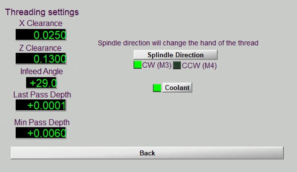
                                                    Hmm. Well it got me puzzled the first time I threaded in M3 and I know others have been confused too from postings on M3 Support. One is used from milling to the CP being the centre of the rotating tool, the lathe is different. Part of the problem is that the M3 thread wizard isn't remarkably clear. This is "settings":

                                                    m3_thread.jpg

                                                    As a novice to Mach3, what "splindle" direction would you select for a RH thread? The correct answer is CW but for a lathe user that's reverse. Clearly the UI was designed by a software engineer.

                                                    #631183
                                                    norm norton
                                                    Participant
                                                      @normnorton75434

                                                      To set any worried minds at rest, I am not at all distressed at how I have been required to label my lathe DRO axes. I was just a little interested in the history as to when this might have come about. My tongue was slightly in the cheek.

                                                      I like the suggestion that the labelling of the axes was well before the time of DRO's and dates to the very earliest, complex automated machinery.

                                                      We all seem to be happy that the convention for milling machines in mapping X, Y and Z is agreed. This suggests that hobbyist equipment is being labelled in a similar manner to the types of industrial machine.

                                                      The interesting difference is in the lathe. There seems to be a consensus on what (I assume) is big industrial use for the spindle axis to be Z, and this make a lot of sense. If you take a great big mill, lay it on its side, the machine might look lathe-like but that spindle direction is still Z.

                                                      Perhaps we have a distinction between big industry and hobbyist/small industry suppliers of of scales and DROs. The responder who helpfully used bold type to point out my error in their eyes with a quote – "Who labelled the axes for DROs on a lathe as X and Y? You did." might note that I was following the supplier's manual. I have seen three different manufacturer's manuals that all agree on the small lathe X and Y labelling.

                                                      I have now fitted DRO's to four machines and if you obtain a two-axis lathe kit it comes with a X and Y labelled DRO. The X control has a specific function to x2 (times two) the X axis movement and it helpfully illuminates a 'diameter' LED. Therefore you cannot swap X and Y and retain this function.

                                                      If you obtain a three axis lathe DRO kit (hobbyist again) and put the Z scales in the top slide, then the Y and Z can be 'added' by a DRO push button. This is quite helpful on my Myford when you bring the saddle up to the work and finish with a few thou of cut on the top slide (set true on the Y axis) – the Z display will show the total travel into the work.

                                                    Viewing 25 posts - 1 through 25 (of 34 total)
                                                    • Please log in to reply to this topic. Registering is free and easy using the links on the menu at the top of this page.

                                                    Advert

                                                    Latest Replies

                                                    Viewing 25 topics - 1 through 25 (of 25 total)
                                                    Viewing 25 topics - 1 through 25 (of 25 total)

                                                    View full reply list.

                                                    Advert

                                                    Newsletter Sign-up