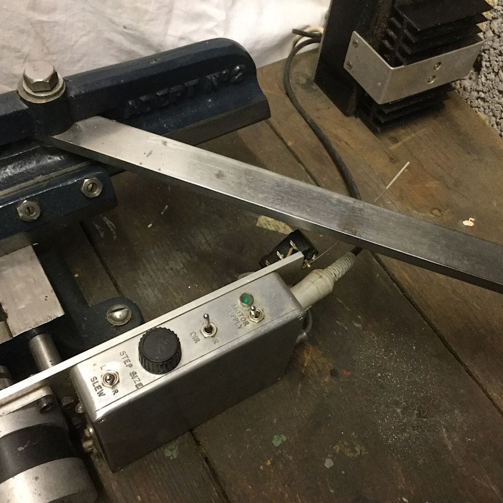
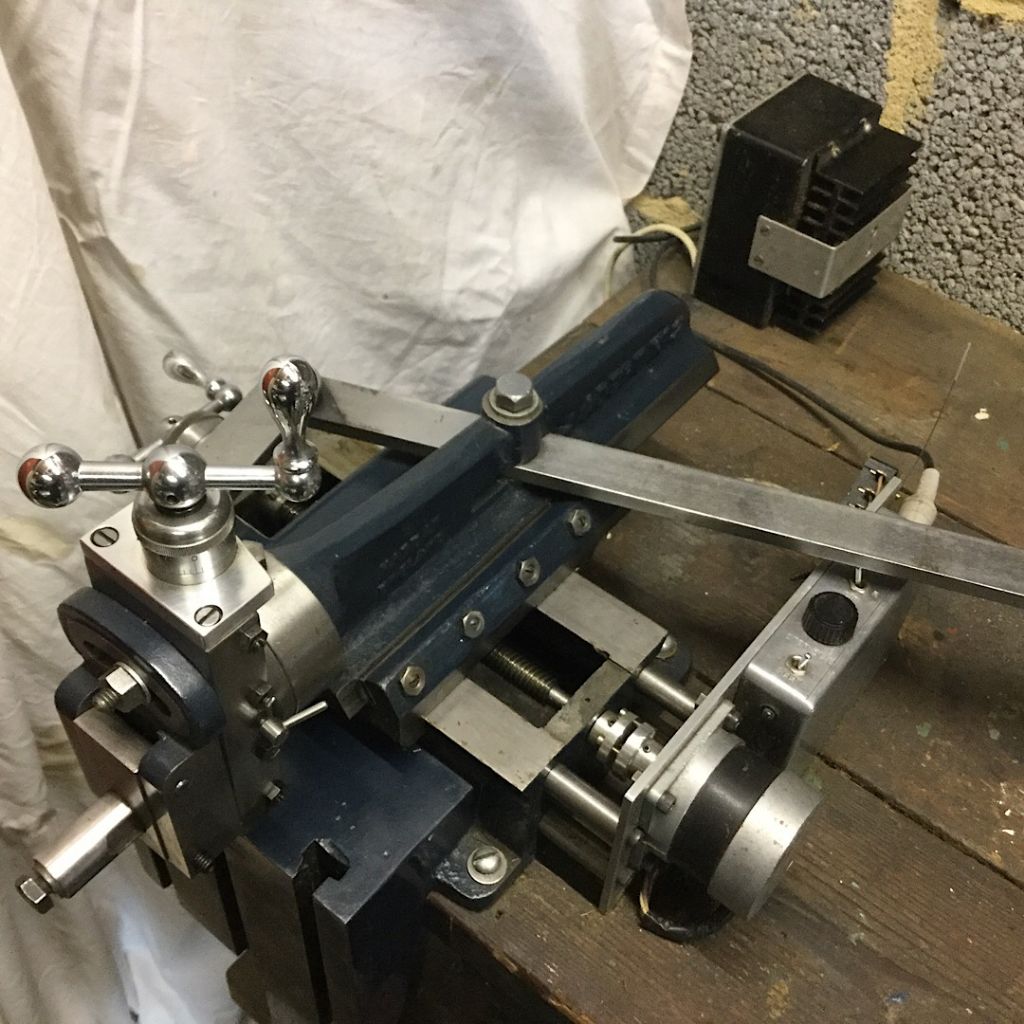
My Drummond manual shaper's been busy lately!
I've just fitted a 3-ph motor set to my Harrison L5 lathe, and made the pair of tensioning arms holding the motor frame above the headstock* , from bits of old miniature-railway rail that our Mam would have said "looked as if they'd been dragged though a hedge backwards". They almost had been, left stacked among shrubs and dead leaves.
That shaper gave a pretty decent finish on the two shorter parts of the arms, more importantly with no rocking when tested on the table of my Meddings bench-drill. It did take a long time to cut below the worst of the rust pits, and I ended up with a sore shoulder, but it was otherwise rather relaxing and satisfying.
I chickened out and milled the mating faces on the longer arms, and the slots in the shorter ones!
As a point of model-building integrity, it occurred to me that a really good shaper finish would not only be functional but also right in looks for surfaces whose prototypes would indeed have been shaped or planed.
It's worth searching out older reference-books on shapers and shaper-tooling, and noting that the cutting edge should be under the clapper-box fulcrum to minimise digging-in. It was also common to use spring-tools, but this is less essential.
This means borrowing your lathe's tools may not be right. I recall seeing one poor shaper holding a lathe tool not only too deep itself, but packed out to push the edge even further forwards. I was too polite to query this with its operators, in a demonstration workshop at A Major Model-Engineering Exhibition!
I also file a small chamfer on the entry edge of the work-piece, slightly reducing the shock as the tool starts cutting.
For internal key-ways and splines, it is normal to draw-cut with the clapper-box locked. Some books show a locking bar screwed across the box. If you don't want to risk modifying the machine in a way that weakens the clapper-box holder, you can use a tool-holder with a jacking-screw in a top end that projects above the clapper-box.
For those who like making tools (to make more tools?) there exists an old design principle for a secondary table that allows a shaper to cut large-radii concavities such as smoke-box and motor saddles. This alternative to rather alarming fly-cutting, uses the geometry of rigid guides constraining the sub-table to move horizontally and vertically, simultaneously, so at each increment it forms a new tangent to a constant arc.
Most people motor-driving a manual shaper probably use these machines' usual crank and swinging-arm, but given that higher return-stroke speed is less important in amateur than production work, I have wondered if a self-reversing screw-drive would work here. It would be a challenge to thread-mill a full L+RH reversing-screw, but its main disadvantage is the fixed travel. I think my dear little Drummond will remain driven by an H.Sapiensis powered by tea!
*Lathe motor. The original Harrison L5 motor-mount was a massive steel box welded to the back of the cabinet, forcing the machine a long way out from the wall. To regain this lost space in a cramped workshop, I have cut the box off, and placed the new motor on a wall-frame over the headstock. It also raises the motor away from the dark and dusty depths.
vintage engineer.


