Hi Andrew,
I think that the information in the Gears and gear cutting book is just there to
make the point that there must be some clearance between meshed gears ,
just working that out on 20 DP size of gears using the 48 / 52 ratio gives a
backlash of 0.0063 inch ,i would have though that was too much.
Obviously the ideal situation would be to have the correct tooth profile ie
cut to the correct depth so that both gears mesh at pcd with the correct
backlash ,i doubt that could happen if the gears were cut with a ratio of
50 / 50.
The extract taken from a book that i have would seem to suggest what
you have said is correct to get some more backlash is to cut deeper ,the
photo of this is in the gears album.
I think the problem in some cases can be the lack of information ,the hobs
that i use are from Arc euro and have no information as to the infeed depth
only the setting angle for the helix.As i eventually found out the infeed is the
full depth of the cutter to the root in this way the correct tooth form is
generated,using these to make the internal cutter means that there is no
extra length to the cutting tooth to cut the clearance at the root of an internal
gear.
Many of the problems with internal gears seem to be connected to either
interference when cutting with a pinion type cutter where a part of the
tooth is trimmed during the radial infeed ,or where a fitted pinion contacts
the edge during engagement refered to as trochoidal interference .
In both these cases it seems this is related to the difference in the number
of teeth between the pinion and internal gear.As you have pointed out these
connections are related to PA ,addendum and DP.
The book i am refering to indicates a difference of 11 teeth between the
pinion and gear ,this seems to vary in some publications.
The 14 and 21 gears shown in one of the photos have only a 7 tooth
difference but still run together well without interference .i think this
is down to the modified form ,the gears can only be assembled
axially and for that reason the internal form was broached.
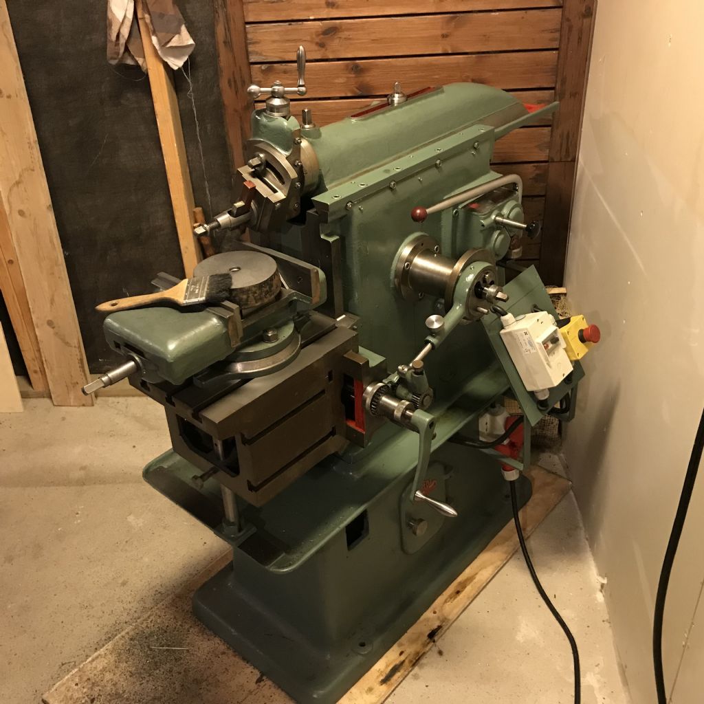
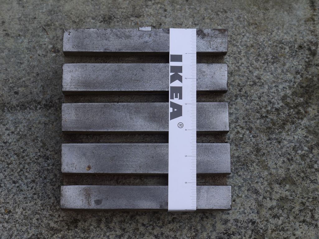
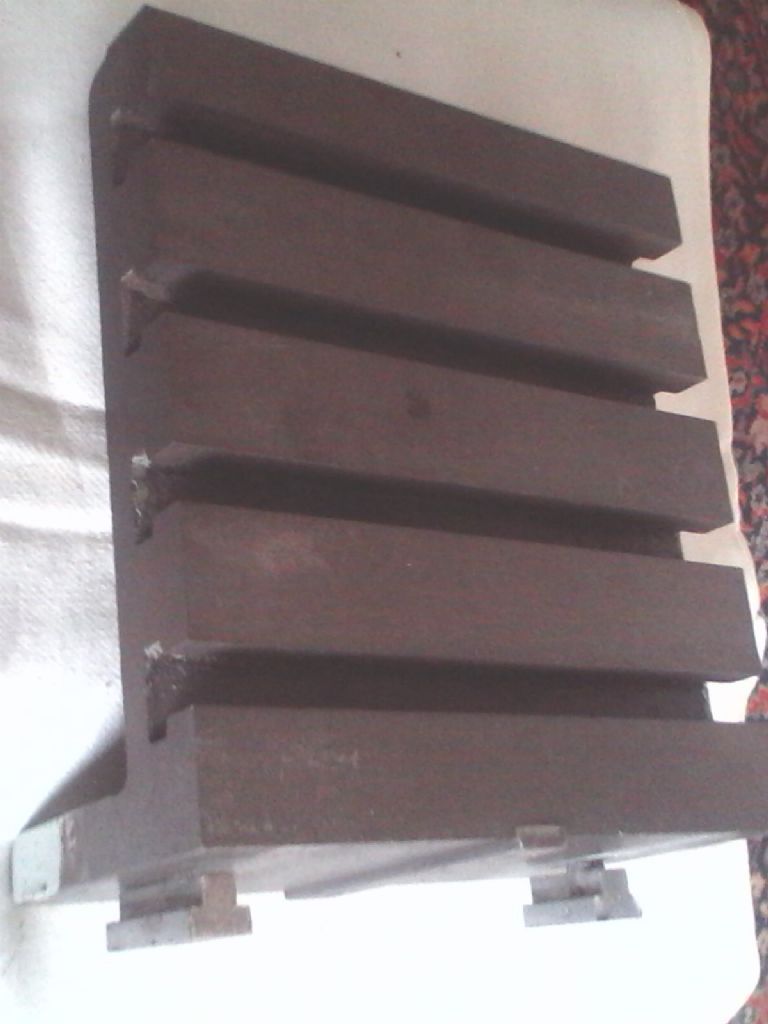
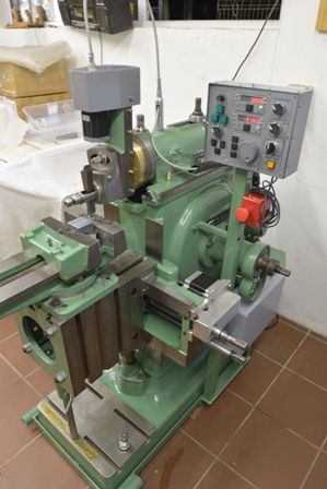
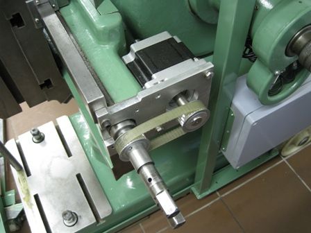
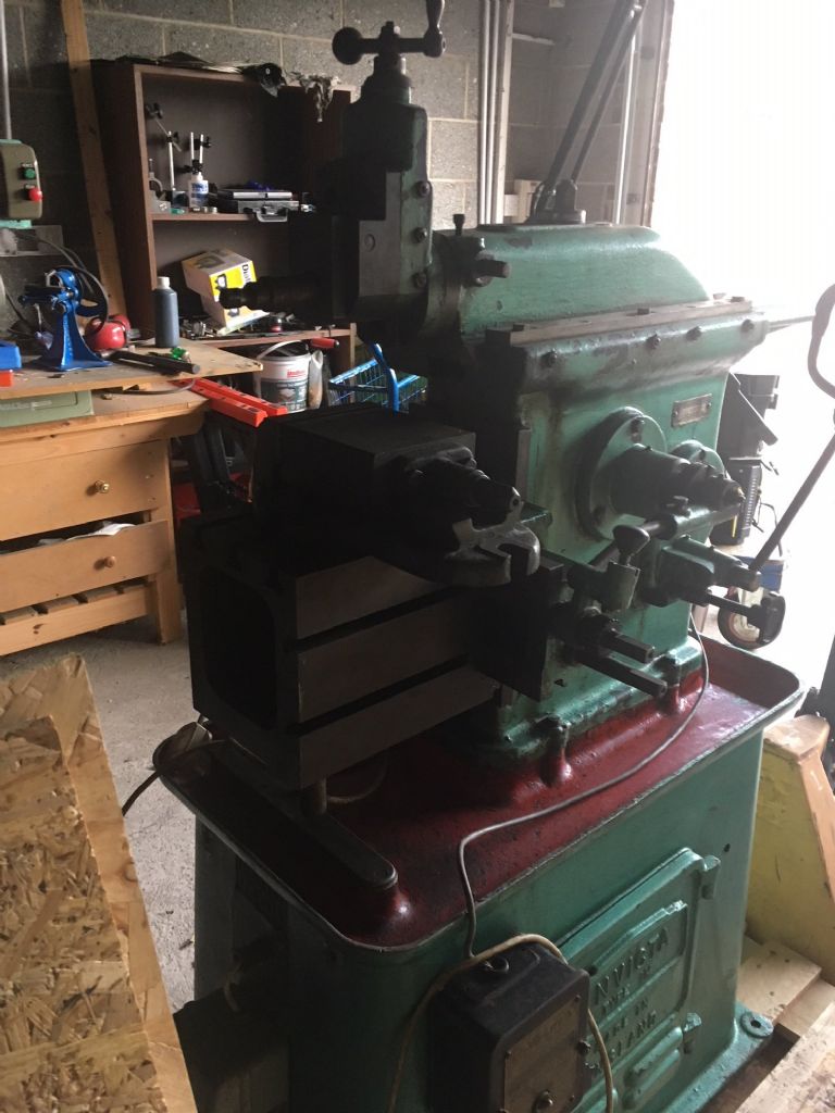
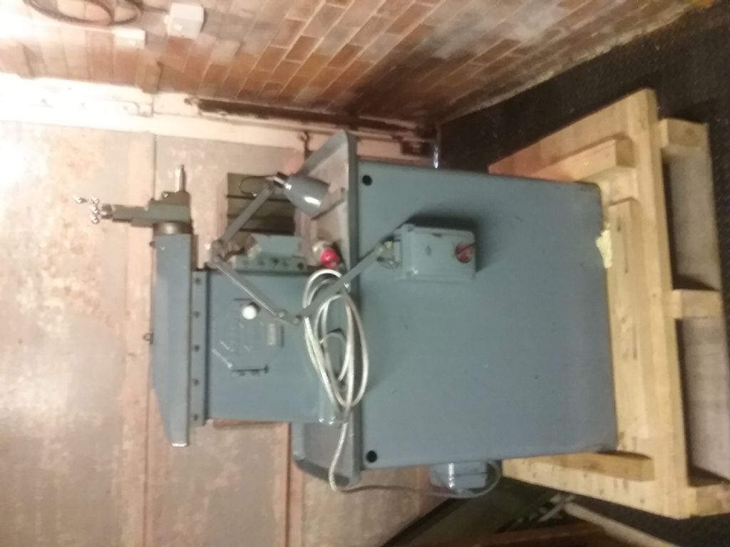
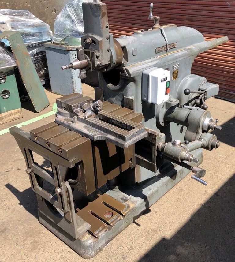
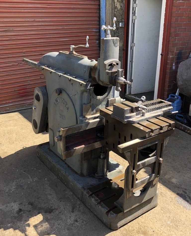
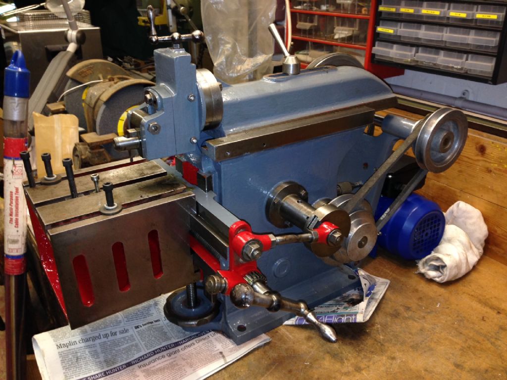
Getting back to the shaper part of this thread i am in the process of making
a fabricated shaper ,there are some photo's in my albums ,at present the
project has stalled but when done will have some stepper motors fitted ,like
all of the rest of my cnc machines it runs on Compucut,Richard Bartlett was
kind enough to write a special file to be used on this machine which sets
the ratio to control two rotary tables , one is a proper rotary table and the
other is a cutting head which will fit on the ram,as part of the file the motors
only move on the rearward movement of the ram ,as long as the file runs the
two remain in syncronization. Using a similar 20 tooth cutter to the one
seen cutting the 36 tooth internal gear and using a ratio of 2 to1 equals
40 teeth on the rotary table ,using a ratio of 6.35 equals 127 .One could
see how useful this could be as every tooth number can be generated
from about 32 (internal) upwards to the physical limit of the machine.
It only leaves to problem on producing the cutter ,here again the shaper
comes to the rescue as the machine that i am building will have stepper
motors on the table and the column ,using the table traverse and the rotary
table it becomes possible to traverse and rotate a blank in time to generate
an involute form cutter just using a single point tool ,although the process
would not be quick using a pre-gashed blank would be a sensible option.
I see from an earlier posting the price of some internal cutters can be
£1200 ,i think for most shed men using about 12 pence worth of silver
steel to make a cutter could be an attractive proposition.
It probably seem a lot of work to produce a machine to cut these gear
forms but shapers it seems have many other uses as well as to holding
down a piece of floor.
John
vintage engineer.


![img_20190205_162350920[1218] boxford.jpg img_20190205_162350920[1218] boxford.jpg](/wp-content/uploads/sites/4/images/member_albums/173113/823648.jpg)

