 Hi guys
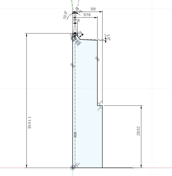
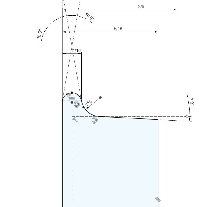
I am also dissatisfied with the dimensions given.
The wheel has two models of operation, straight and near-straight running on the coned tread, as illustrated in all books about locomotives, and scrubbing round "tight" radii, as in junctions and almost all model applications where the track is not dead straight, which Paul ably points out is actually more critical to safety.
In the drawing those two systems are not tied by a tolerance, so the 1/16"R is floating in space, with a multitude of tolerance build-up deciding where it is. Obviously the designer intended all dimensions to be absolute with a form tolerance on top, but it doesn't help the machinist at all.
As a total amateur machinist I would want to use a 1/16 radius tool, touch off the back plate and move across exactly the distance to put it in the right place, feed in to diameter, allowing for the tangent, then feed across on the compound slide at 3 degrees. Then all running surfaces are in the right place and accurate. Obviously roughing is required and I am sure the pros have more sophisticated methods.
I have always found wheel geometry baffling and I think I now know why. 
Roger Best.


