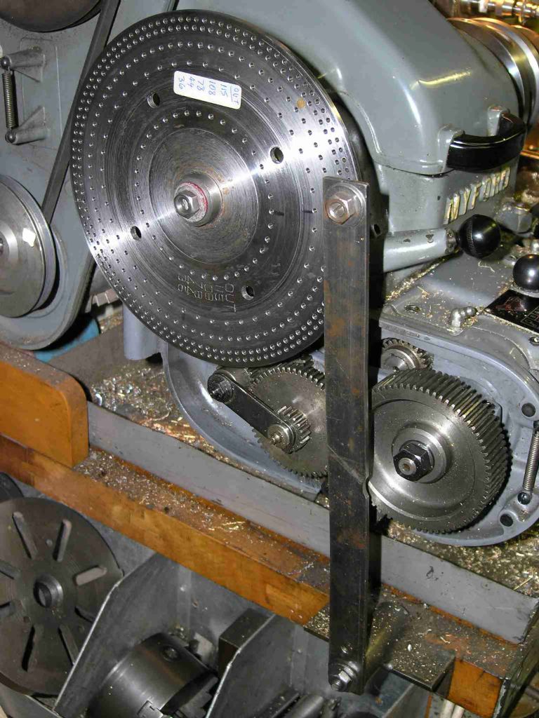
Wheel Cuting thin tooth?

Advert

Wheel Cuting thin tooth?

Home Forums Clocks and Scientific Instruments Wheel Cuting thin tooth?

Viewing 25 posts - 26 through 50 (of 56 total)
  • Author
    Posts
  • #81460
    Bazyle
    Participant
      @bazyle
      Rather than cutting more brass why not put on your faceplate, blue the edge, and scribe lines. The greater diameter will make errors even more visible. You can repeat several times at no cost. In fact you should be able to go round and round and round with every line falling precisely on the last cycle if nothing slips.
       
      Advert
      #81474
      Terry Lane
      Participant
        @terrylane
        “Blank size won’t cause this error; blank too small, all teeth slightly too thin and vice versa.”
        Ah, but what happens if the blank is the wrong size and the (correct)  depth of cut is set on said incorrect blank? (I don’t know, just posing the question).

        Edited By Tel on 07/01/2012 05:35:10

        #81480
        blowlamp
        Participant
          @blowlamp
          Posted by Tel on 07/01/2012 05:34:06:

          “Blank size won’t cause this error; blank too small, all teeth slightly too thin and vice versa.”
          Ah, but what happens if the blank is the wrong size and the (correct) depth of cut is set on said incorrect blank? (I don’t know, just posing the question).

          Edited By Tel on 07/01/2012 05:35:10

          Then all the teeth will be either too thick or too thin.
          Think of a simple spoked wheel: at any given radius, all the spokes will measure the same distance apart provided, they are accurately indexed.
           
          As long as things such as the part slipping whilst cutting aren’t happening, or the original poster is using inaccurate equipment, then this appears to be a case of a cumulative error building up because of some kind of maths error by him.
           
          If direct indexing is being used here and the fault shows every time, then the indexing plate must be faulty.
           
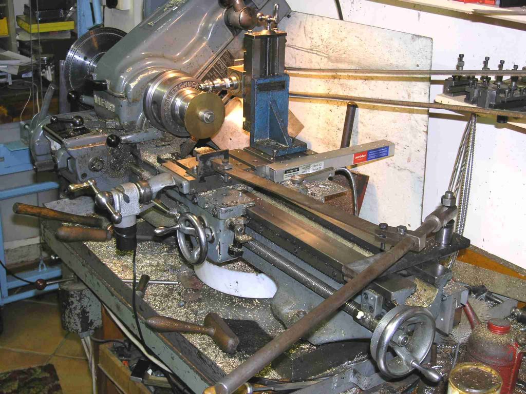
          A good picture of the whole setup might help us here.
           
           
          Martin.
          #81501
          Steve Withnell
          Participant
            @stevewithnell34426

            I had this problem cutting a bevel gear for my Victoria. Turned out not to be the rotary table or the dividing plate, but the paper chart that tells you which holes to use. It was only wrong for the specific number of teeth I wanted to cut, all the others were fine (yes I did check them all and printed a new sheet and tossed the manufacturers).

            #81513
            Martin W
            Participant
              @martinw
              Hi
               
              Just a thought but what if a piece of swarf/dirt, for example, had got into the rotary table and onto the pinion gear that the worm drives. Would or could this cause the table to jump when that face of the pinion was in contact with the worm. If the swarf was deep in the pinion thread then the worm would only contact it for a small period and could cause the table to over rotate for that one position, the slack would be taken up as the table was wound on to next position; similar to backlash.
               
              The above assumes that the division plate has the correct number of holes in it. Just done a quick calculation and for a 90:1 ratio drive a 23 hole index plate is required using 18 hole intervals, for a 40:1 ratio drive again a 23 hole index plate is required but the interval is now 8 holes.
               
              Regards
               
              Martin
               
              PS
               
              If anyone is interested I have written an Excel spreadsheet that uses the drive ratio and and index plate hole sets to calculate the set up for obtaining a particular division ratio. This can be presented as a table for a range of division ratios or a particular division ratio can be typed in. The data is presented as the number of complete revolutions and extra index plate holes, if required, for each division under the relevant index series. Will put a copy to show the output in my album later.

              Edited By Martin W on 07/01/2012 15:35:36

              #81516
              Billy Mills
              Participant
                @billymills
                Although Peter has tested the plate I don’t see that it is likely to be anything else. It is interesting that Peter DID NOT use the plate with a rotab, the rotab was used to make the plate then the plate was then used on it’s own as a direct index to cut the gear.
                 
                As Peter has cut four identical gears with one bad tooth it is something very predictable creeping cutters or eccentric mounting would hardly fit, a worn or eccentric pin in the plate would not fit the fault. Relative movement between the cutter and the indexing axis would fit but the same movement four times?
                 
                Two questions for Peter- did you always start cutting from the same starting hole in the indexing plate? Was the thin tooth always the last tooth?
                 
                Billy.
                #81523
                Martin W
                Participant
                  @martinw
                  Hi Billy
                   
                  Just looked back over the thread and seen I was coming from the wrong direction. As you say Peter is using a direct indexing system and not a rotary table so that aspect of it is out of the window.
                   
                  If as Peter says he is directly indexing from a 115 hole index wheel and the wheel and blank are securely attached to the same shaft then could there be some sort of creep of the cutter or the arbor. Even so it would still have to be a fairly uniform creep not to show up as a thicker tooth somewhere before the thin one.
                   
                  Baffled
                   
                   
                  Martin
                  #81531
                  Richard Parsons
                  Participant
                    @richardparsons61721
                    Martin – Peter wrote “The Direct indexing from a plate on the end of the spindle, made the plate last year using a rotary table, drilled twice so that we could check for errors”.
                    That is where the Errors crept in. sure the plate has 115 holes in it and they are evenly spaced but each hole is a little bit wrong in its position. I will bet that the distance between the first and last hole is wrong. But there are 115 of them.

                    Oh a golden rule is ‘Never turn it backwards or if you must turn it far enough to take up the backlash!

                    #81534
                    Martin W
                    Participant
                      @martinw
                      Hi Richard
                       
                      I can see where you are coming from but looking at Peter’s last post on 6 Jan he says that he used a DRO system to measure the position of the holes on the index plate and didn’t find an error even though he went round twice. If there were problems with the plate then I would have expected them to show up during this exercise . Going on this I was clutching at straws trying to find a reasonable/plausible or any explanation for his problem.
                       
                      I even toyed with the idea that the cutter was actually cutting the back of the first tooth as it came full circle because the PCD was to small. But as this is an angular increment that goes out the window as well .
                       
                      We really need to see a picture of the entire set up as was suggested earlier in this thread. Still it has caused many of us to scratch our heads and disturb the little grey cells a bit .
                       
                      Cheers
                       
                       
                      Martin
                      #81535
                      Billy Mills
                      Participant
                        @billymills
                        Richard, we both suspect the same cause. Peter has checked the spacing however I think that despite the checks the first and last holes are out. When you are trying to find the answer to a mystery the simplest most direct tests are often the best- but don’t trust assumptions-one of them has let in the error.
                         
                        Out with the verniers and check the hole spacing!
                         
                        Billy.
                        #81536
                        Billy Mills
                        Participant
                          @billymills
                          Quick thought, support the plate horizontally above the bench on a jam jar with a torch bulb above so that the light goes through every hole onto the bench to give overlapping circles of light. Is there an irregularity in the overlap somewhere around the circle?
                           
                           
                          Billy.
                          #81537
                          Les Jones 1
                          Participant
                            @lesjones1
                            Hi Peter,
                            How about making two scans of the indexing disk. One from each side so that when you print them out they will be mirror images. lay the two printouts on top of each other and look to see if any of the images of the holes do not line up. I did originally think of rotating two prints of the same scan with respect to one another but distortion in the scan or print would give confusing results.
                             
                            A picture of your setup may also  may give members more  ideas as to the cause of the problem.
                            Les.

                            Edited By Les Jones 1 on 07/01/2012 18:59:25

                            #81560
                            Michael Gilligan
                            Participant
                              @michaelgilligan61133

                              Peter,

                              Assuming that you have confirmed the accuracy of your division plate … Your first suggestion is, I am sure, correct.

                              The blank is too small [and/or you are taking excessively deep cuts; which ammounts to the same thing].
                              Either way; when you cut teeth to leave little or no “witness” on the tips, you are effectively working to a circumferential pitch, and the circumference is too small to accommodate the full set of teeth … therefore the last tooth will be thin.

                              Try cutting another wheel without going full depth … then measure it.

                              Good luck

                              MichaelG.

                              #81564
                              Billy Mills
                              Participant
                                @billymills
                                Changing the diameter of the wheel does NOT alter the angular position of the gaps cut. Imagine having a double sized blank and cutting the 115 gaps, the gaps would look a little lonely but they would be in exactly the same angular relationship as a correct size blank. That is because they are in exactly the same relative angular position as the holes in the plate.
                                 
                                That assumes that the cutter has not moved relative to the axis of rotation of the blank however you would think that the cutter would be secure and would not move the same four times running and the rest of the equipment would stay put. If there are loose or slack components you would think that it would have been noticed. Wear or eccentric mounting would not cause the one tooth error, the cut would smoothly vary 1 cycle around the wheel, not all be at one end.


                                Billy.
                                #81570
                                Richard Parsons
                                Participant
                                  @richardparsons61721
                                  There is one thing we have not looked at yet. It is the cutter.

                                  Peter I presume that you are cutting an involute wheels Module 0.75.
                                  Since you are not using a Hob but a single tooth cutter you need to be aware that for each Module (or D.P.) there are 8 cutters (plus another 7 for high accuracy). These cutters are for different numbers of teeth. For 115 teeth you would need a No 2 cutter (55 to 134 teeth) or for high accuracy a No 1 ½ cutter (80 to 134 teeth).
                                  Which one have you got? Thorntons are an outfit of very high repute but mistakes do occur. If it is a No2 cutter it might be worth you getting contact with them.

                                  Rdgs
                                  Dick
                                  #81571
                                  Michael Gilligan
                                  Participant
                                    @michaelgilligan61133

                                    Changing the diameter of the wheel does NOT alter the angular position of the gaps cut.

                                    Billy,
                                    … Yes, that’s perfectly true.

                                    MichaelG.

                                    #81572
                                    Peter Bell
                                    Participant
                                      @peterbell11509
                                      Hello everyone and thanks for all the helpful comments.
                                       
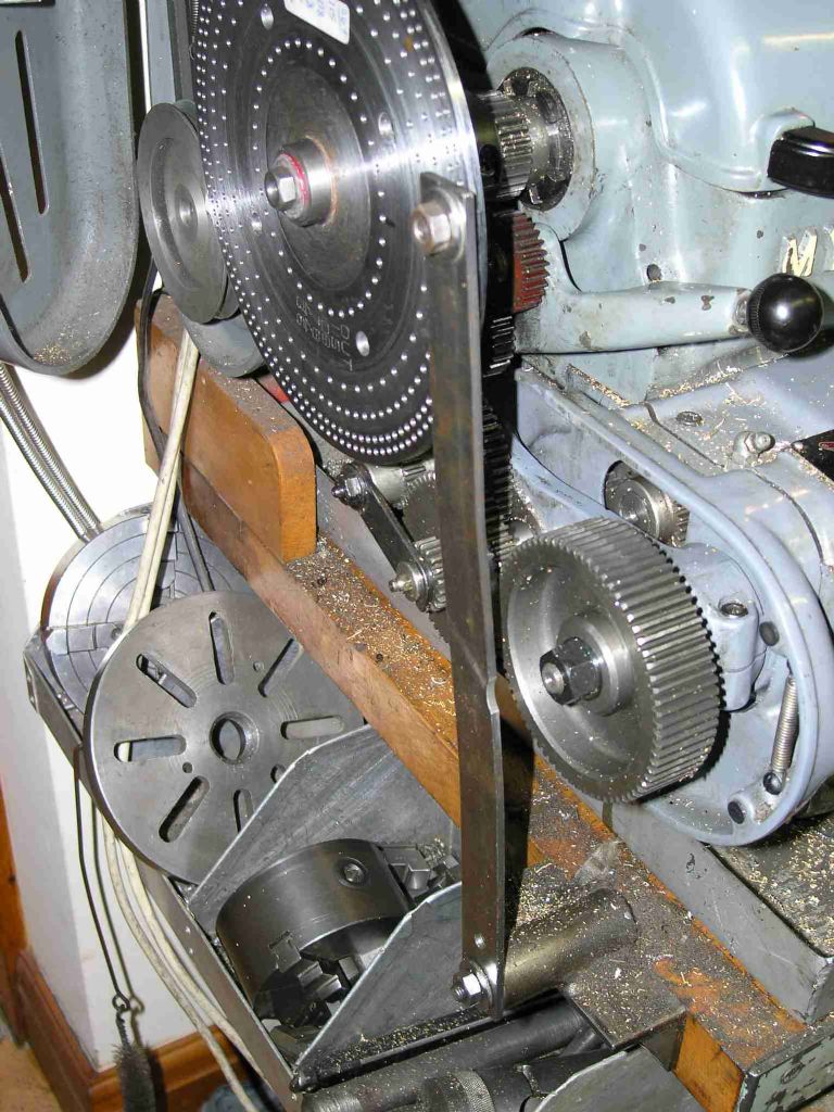
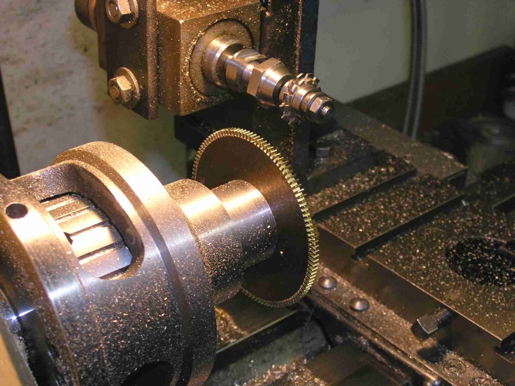
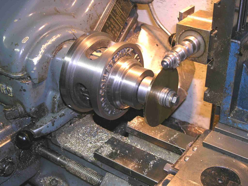
                                      I have cut a 115t 0.75m wheel as a test in 1/8″ cz120 and also a 115t 0.5 m wheel and both have turned out fine this time! at least as far as I can see. This time I have potographed the setup and scanned the wheels.
                                       
                                      Before cutting I checked everything over very carefull, everything was tight and all slides locked and cut adjacent teeth until a tiny witness was left at the tip. They were then all cut at one pass as I normally do with the cutter running at about 4000rpm, the 0.75m blank should have been better supported but I coulnt find any suitable washers.
                                       
                                      So it looks like the division plate was ok. I know it shouldnt make any difference but I I wondered about my blanks size calculation as the calculator batteries were almost flat, changed them but got the same numbers. My digital calipers are slightly magnetic and attrract swarf and you sometimes get a false zero.
                                       
                                      I think that may have influnced my initial blanks size as the thin tooth wheels were 3.472″ dia and the one just cut is 3.484″ very close to the calculated 3.481″
                                       
                                      So not really sure what went wrong but will recut them again when the replacement brass arrives, fingers crossed!
                                       
                                      Regards Peter
                                       

                                      #81575
                                      Michael Gilligan
                                      Participant
                                        @michaelgilligan61133

                                        Well done, Peter … and thanks for posting the evidence.

                                        Despite your sucess; I’m sure this discussion will continue for a while … and it will provide a useful reference for anyone that hits similar problems in the future.

                                        MichaelG.

                                        #81576
                                        Peter Bell
                                        Participant
                                          @peterbell11509
                                          Hello Dick,
                                           
                                          I wondered about the cutter but I thought all Thorntons cutter were cycloidal, mine just says M 0.7W on it. The wheel are for the barrels in a CB Reeve year going clock.
                                           
                                          Regards Peter
                                          #81582
                                          Les Jones 1
                                          Participant
                                            @lesjones1
                                            Hi Peter,
                                            First I agree with all of the comments discounting the size of the blank. The same also goes for the shape of the cutter. The problem is to do with the ANGLE of rotation of the blank between the teeth. Looking at the way the strap on which the indexing pin is mounted makes me think this could be a source of the problem. I assume that the nut at the bottom end of the strap is not undone during indexing. If it is was play in this hole could be the problem. I am assuming that you just flex the strap to index between holes.
                                            The way the bottom of the strap is fixed to the bench rather than somewhere on the headstock casting could be the problem as any movement in the bench between where the lathe is bolted to it and the bottom strap fixing would cause errors. The only other thing I can think of is end float in the cutter shaft but you have probably already eliminated that.
                                             
                                            Les.
                                            #81583
                                            blowlamp
                                            Participant
                                              @blowlamp
                                               
                                              The second wheel in your picture is duff at the 10:30 position.
                                               
                                              The thing I notice in the third and last of your photographs is that the support arm of the indexing pin is anchored to the bench rather than the lathe.
                                               
                                              If the lathe is able to move in relation to the bench – and hence the the arm – then a slight rotation of the headstock spindle will occur and give the error we are seeing.
                                               
                                              Is the lathe firmly secured to the bench so that it can not creep across it?


                                              Martin.
                                              #81591
                                              Billy Mills
                                              Participant
                                                @billymills
                                                If the three wheel pictures are the latest cut and given that the second has a thin tooth then something is loose or the cutting procedure has changed for the second wheel. It would be good to mark the first notch when cutting the next wheel and the starting position for the index plate. With a cut wheel mounted how much can you turn the wheel- i.e. how much backlash in the pin/plate/mandrel/ wheel system? How much can you move the culler along the spindle axis?
                                                 
                                                It could be that the apparent rotation is in the first cut or the last cut . Not at some other position because that would produce two bad teeth, but it has not happened every time. So the evidence suggests that the plate is good but that some other gremlin sometimes moves stuff at the beginning or end.
                                                 
                                                Billy.
                                                #81595
                                                Peter Bell
                                                Participant
                                                  @peterbell11509
                                                  It looks like the captions did not come through with the pictures, not sure what I did wrong? The middle wheel with the thin tooth is one of the originals, the top and bottom ones are new, cut last night.
                                                   
                                                  The arm does indeed flex and is springy enough to allow it to be pulled back to index to the next hole and it locates with a firm clunk. Agree that the mounting could be better as it is only screwed to the wooden bench but just checked and the lathe is till firmy bolted down and the arm bracket is screwed tight. It would have been nice to report that something was loose!
                                                   
                                                  Peter
                                                  #81596
                                                  Jens Eirik Skogstad 1
                                                  Participant
                                                    @jenseirikskogstad1
                                                    I has same setup in my lathe each time i am making geat wheel or other work such as hole for cylinder head, turbine wheel and et cetera..
                                                     
                                                    1. rule: No play in the lathe/millinghead!
                                                     
                                                    Check all slides and bearing in the lathe/millinghead are without play with force of hand (move the sliding or bearing in all rights of way) when you are checking the parts in lathe are without play. Check play with dial gauge if neccesary.
                                                     
                                                    Is there chattering/vibration of lathe/millinghead when you are making the gear wheel?
                                                    Is the blank wheel/indexing disc firmly secured? (Can not rotate with force by yours hands)
                                                     

                                                    Edited By Jens Eirik Skogstad on 08/01/2012 14:08:29

                                                    #81597
                                                    Billy Mills
                                                    Participant
                                                      @billymills
                                                      Did you turn off the cutter drive while the cutter was in the last slot before retracting the cutter ? or always retract before turning off. If both then it could be that the cutter is moving the few thou when driven so most slots are cut with a rotating cutter approaching the slot. On the last slot if power is removed after the slot is cut the cutter could move over whilst slowing down and shave the last tooth.
                                                       
                                                      It could be something like this because you have proven that the equipment and the operator can produce good wheels.
                                                       
                                                      Billy.
                                                    Viewing 25 posts - 26 through 50 (of 56 total)
                                                    • Please log in to reply to this topic. Registering is free and easy using the links on the menu at the top of this page.

                                                    Advert

                                                    Latest Replies

                                                    Viewing 25 topics - 1 through 25 (of 25 total)
                                                    Viewing 25 topics - 1 through 25 (of 25 total)

                                                    View full reply list.

                                                    Advert

                                                    Newsletter Sign-up