What’s the tolerance??
What’s the tolerance??
- This topic has 15 replies, 12 voices, and was last updated 4 July 2020 at 12:43 by
Bob Wild.
- Please log in to reply to this topic. Registering is free and easy using the links on the menu at the top of this page.
Latest Replies
-
- Topic
- Voices
- Last Post
-
-
Use horizontal mill as saw for metal?
Started by:
 ell81
in: Beginners questions
ell81
in: Beginners questions
- 16
-
9 April 2025 at 23:13
Dave Halford
-
Steam pressure using thermistor
1
2
Started by:
michael howarth 1
in: General Questions
- 16
-
9 April 2025 at 22:59
duncan webster 1
-
Potential new society in North Yorkshire
Started by:
cliff almond 1
in: Model engineering club news
- 6
-
9 April 2025 at 22:49
Nigel Graham 2
-
N Devon Model Engineers, is this the end?
Started by:
Engine Builder
in: Model engineering club news
- 10
-
9 April 2025 at 22:45
Nigel Graham 2
-
Motor bearings and more
Started by:
Sonic Escape
in: General Questions
- 3
-
9 April 2025 at 21:00
Macolm
-
Hello
Started by:
tbm
in: Introduce Yourself – New members start here!
- 3
-
9 April 2025 at 20:07
noel shelley
-
Re-Visiting My Stuart Victoria
Started by:
Steve Withnell
in: Work In Progress and completed items
- 1
-
9 April 2025 at 17:15
Steve Withnell
-
Good quality Jewellers screwdrivers.
Started by:
Andrew Tinsley
in: Workshop Tools and Tooling
- 8
-
9 April 2025 at 16:51
Robert Atkinson 2
-
Small type Reilang oil gun
Started by:
john fletcher 1
in: General Questions
- 1
-
9 April 2025 at 16:49
john fletcher 1
-
Half Scale 1/4HP A J Weed Engine
Started by:
JasonB
in: Stationary engines
- 4
-
9 April 2025 at 16:45
JasonB
-
Myford 254S Lead screw lever issue
Started by:
alan1b
in: Help and Assistance! (Offered or Wanted)
- 3
-
9 April 2025 at 16:40
Dave Halford
-
Building Bernard Tekippe’s Precision Regulator
Started by:
Chris Raynerd 2
in: Clocks and Scientific Instruments
- 3
-
9 April 2025 at 15:12
Chris Raynerd 2
-
DIY Pendulum Timer – GPS-Synced Beat Analyser
1
2
Started by:
Chris Raynerd 2
in: Clocks and Scientific Instruments
- 7
-
9 April 2025 at 14:01
Bazyle
-
DC Wasp Rebuild
Started by:
William Chitham
in: I/C Engines
- 6
-
9 April 2025 at 09:40
petetwissell
-
24cc DIESEL ENGINE FROM SOLID
Started by:
dean clarke 2
in: I/C Engines
- 9
-
9 April 2025 at 09:37
petetwissell
-
Autodesk Fusion Discount
Started by:
Alan Wood 4
in: CAD – Technical drawing & design
- 4
-
9 April 2025 at 09:32
John Hinkley
-
Measuring increments on boring head
1
2
Started by:
Bill Phinn
in: Workshop Techniques
- 16
-
9 April 2025 at 08:51
JasonB
-
taper pins
Started by:
Garry Coles
in: General Questions
- 6
-
8 April 2025 at 21:19
Nimble
-
Myford Super 7 restoration problem.
Started by:
Bootlegger Blacky
in: Manual machine tools
- 4
-
8 April 2025 at 20:39
Bootlegger Blacky
-
Damp proofing concrete floors
Started by:
Duff Machinist
in: General Questions
- 15
-
8 April 2025 at 15:56
Chris Crew
-
Contact Details for the family of Alan Barnes
Started by:
Neil Wyatt
in: General Questions
- 1
-
8 April 2025 at 14:05
Neil Wyatt
-
Myford saddle lock issue
Started by:
Andrew Moyes 1
in: Manual machine tools
- 1
-
8 April 2025 at 13:16
Andrew Moyes 1
-
New member old lathe
Started by:
t1krt
in: Introduce Yourself – New members start here!
- 8
-
8 April 2025 at 12:36
parovoz
-
Reader Survey
Started by:
Neil Wyatt
in: Model Engineer & Workshop
- 14
-
8 April 2025 at 12:31
parovoz
-
Easing out the bore of a 3-jaw, s/c chuck
Started by:
Greensands
in: Workshop Tools and Tooling
- 11
-
8 April 2025 at 11:39
Bazyle
-
Use horizontal mill as saw for metal?
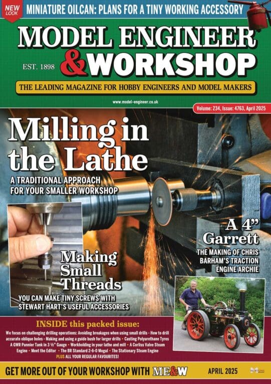
Latest Issue
Newsletter Sign-up
Latest Replies
- Use horizontal mill as saw for metal?
- Steam pressure using thermistor
- Potential new society in North Yorkshire
- N Devon Model Engineers, is this the end?
- Motor bearings and more
- Hello
- Re-Visiting My Stuart Victoria
- Good quality Jewellers screwdrivers.
- Small type Reilang oil gun
- Half Scale 1/4HP A J Weed Engine

