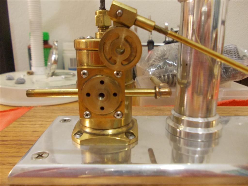
What sort of bolts/screws are these on this Beam Engine ?

Advert

What sort of bolts/screws are these on this Beam Engine ?

Home Forums Stationary engines What sort of bolts/screws are these on this Beam Engine ?

Viewing 11 posts - 26 through 36 (of 36 total)
  • Author
    Posts
  • #175350
    Brian John
    Participant
      @brianjohn93961

      I have ordered a range of hex tools from Model fixings which should be here in a few weeks. Once I have the screws and bolts out then I can measure the length of them and work out what to replace them with.

      Where can I order some springs…who has a big range ?

      Advert
      #175381
      Brian John
      Participant
        @brianjohn93961

        I have found Lee Springs and they seems quite good :

        **LINK**

        So once I get that spring off the valve cover I can measure it. Should I be looking for something about 3/4 as strong…..1/2 as strong ? Or perhaps order a range of springs and try a few ?

        #175459
        Ian S C
        Participant
          @iansc

          Brian, it might be worth shortening the original spring, try a turn at a time, you might even have to stretch it a little. It helps to save old springs from equipment.

          Ian S C

          #175460
          Brian John
          Participant
            @brianjohn93961

            Yes, I will try that eventually. First I will just have a look and see how that valve system works. Then I will try to eliminate any friction in the system ; I think the crank is rubbing against one of the supports. There may be other points of friction. I have to wait for the tools to arrive from the UK.

            Edited By Brian John on 10/01/2015 12:28:13

            Edited By Brian John on 10/01/2015 12:29:31

            #200620
            Brian John
            Participant
              @brianjohn93961

              I have dragged this beam engine out to have a look at it today. The previous owner/ builder had TWO springs on the valve nut. I have found a replacement spring with less tension but I am having problems getting this engine to run at all. I have never fiddled with a beam engine before : how do I go about setting the timing ? I thought I could work it out but after two hours I must admit defeat and ask for help.
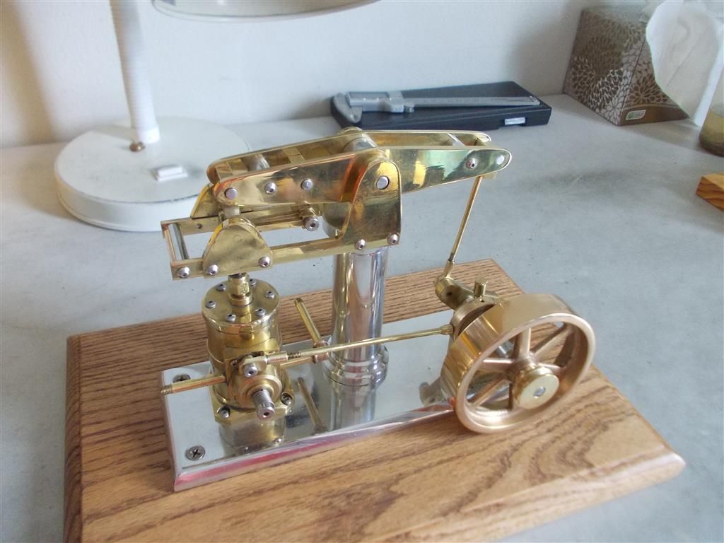
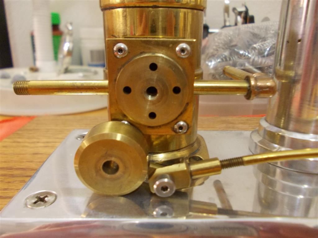
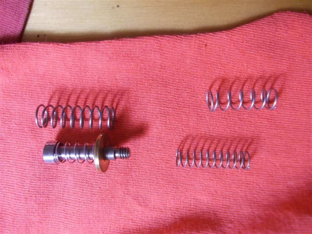
              Below are some photos showing the valve arrangement. The bottom photo shows the springs : the original two springs are on the right. He had used one inside the other. I suspect he had problems getting it to run which is why he sold it !

              dscn0019.jpg

              beam engine valve 2.jpg

              beam engine valve 1.jpg

              beam engine valve  springs.jpg

              Edited By Brian John on 16/08/2015 13:59:53

              Edited By Brian John on 16/08/2015 14:01:36

              Edited By Brian John on 16/08/2015 14:02:31

              #200631
              Neil Wyatt
              Moderator
                @neilwyatt

                Looking at the top picture, it appears that if the flywheel is rotated 45 degrees clockwise the beam will be roughly horizontal and the valve will be roughly at the mid-point of its travel.

                This suggests the eccentric is about 90-degrees out from the correct position.

                The starting point should be to have the valve at approximately maximum travel one way or the other when the piston is at its mid point (beam horizontal). The engine should then run and the eccentric can be adjusted to get the best result.

                You are aiming for the valve to open just as the piston approaches TDC, whatever type of steam engine it is.

                The double spring was probably needed to to stop the large rotary valve lifting and leaking with steam pressure applied.

                Neil

                #200708
                Brian John
                Participant
                  @brianjohn93961

                  Thank you Neil. I have been working on it today and I understand the timing much better ; the engine is running quite well. Plenty of lubrication and a new spring over the valve cover has helped too. The engine will even start without touching the flywheel now. There is still a bit of a clunk/knock but it is nowhere near as bad and I suspect that this is as good as it gets. I have fiddled endlessly with the length of the connecting rods but it does nothing to eliminate it . 

                  Edited By Brian John on 17/08/2015 08:05:35

                  Edited By Brian John on 17/08/2015 08:07:21

                  #200715
                  Douglas Johnston
                  Participant
                    @douglasjohnston98463

                    I am not a model maker myself, but to me the polished brass finish looks very nice and I can't quite understand why you would want to paint it. Is this to do with making it look more in keeping with the original machine?

                    Doug

                    #200747
                    Brian John
                    Participant
                      @brianjohn93961

                      Partly that and also personal preference, But I have decided NOT to paint this beam engine. My lathe will be sent up to me later this week so I will be building my own beam engine.

                      #200982
                      Brian John
                      Participant
                        @brianjohn93961

                        There is still a slight ''bump'' at the end of the stroke but it is running much better than it was. This is my first video with the new phone so I hope it works.

                        **LINK**

                        #201045
                        Bazyle
                        Participant
                          @bazyle

                          If there is a 'bump' it is due to play in the linkage not the length. Quite difficult in a small model to get joints loose enough to move without being sloppy.

                          Glad yo have decided not to paint it. It is clearly designed to be a shiney coffee table 'talking point' model and paint would halve the value apart from making it look like a kids toy rather than an executive model.

                          When you get the screws out please replace them with hex bolts, Those ones with piddling little hex holes look bad even on modern instruments – they are just a bad design. The previous owner told you what the screw sizes are – numbers like '6-32' are how the small UNC and UNF american screws are described with the second number eg 32 being the TPI.

                          What you need is a class case to put it in to reduce the rate of tarnishing.

                        Viewing 11 posts - 26 through 36 (of 36 total)
                        • Please log in to reply to this topic. Registering is free and easy using the links on the menu at the top of this page.

                        Advert

                        Latest Replies

                        Home Forums Stationary engines Topics

                        Viewing 25 topics - 1 through 25 (of 25 total)
                        Viewing 25 topics - 1 through 25 (of 25 total)

                        View full reply list.

                        Advert

                        Newsletter Sign-up