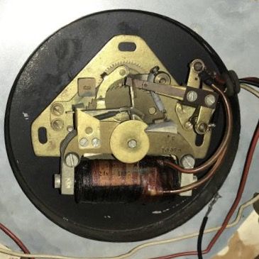
I found a description of the IBM system here on the National Association of Watch and Clock Collector forum in a post by tom11443. He says:
IBM/Simplex Synchronous Correction cycle.
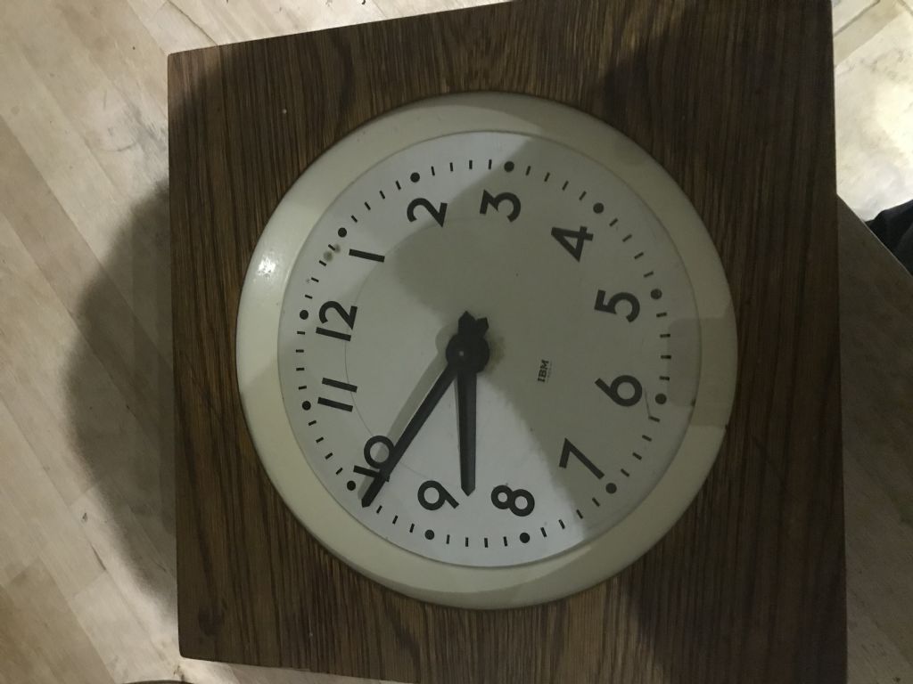
IBM developed this system in the late 1940s to replace the older ‘minute impulse’ systems. They sold their time equipment division to Simplex in 1958. Therefore, any clocks with the IBM logo were manufactured prior to 1958. The same basic protocol & mechanisms remain unchanged to the present. Several other manufacturers, including Latham, Cincinnati, Dukane, Standard Electric Time, use the exact same protocols.
Synchronous Systems
All consist of a master clock & a number of secondary clocks in remote locations. These secondary clocks appear to run like an ordinary plug-in electric clock & run on their own synchronous electric motor and will maintain correct time unless there is an interruption in electric service, depending on the master clock only for the periodic synchronizing impulse. These clocks differ from the ‘impulse’ type, which are electrically advanced each minute by the master clock. Impulse type clocks are usually called ‘slave’ clocks since they cannot function at all without the master clock.
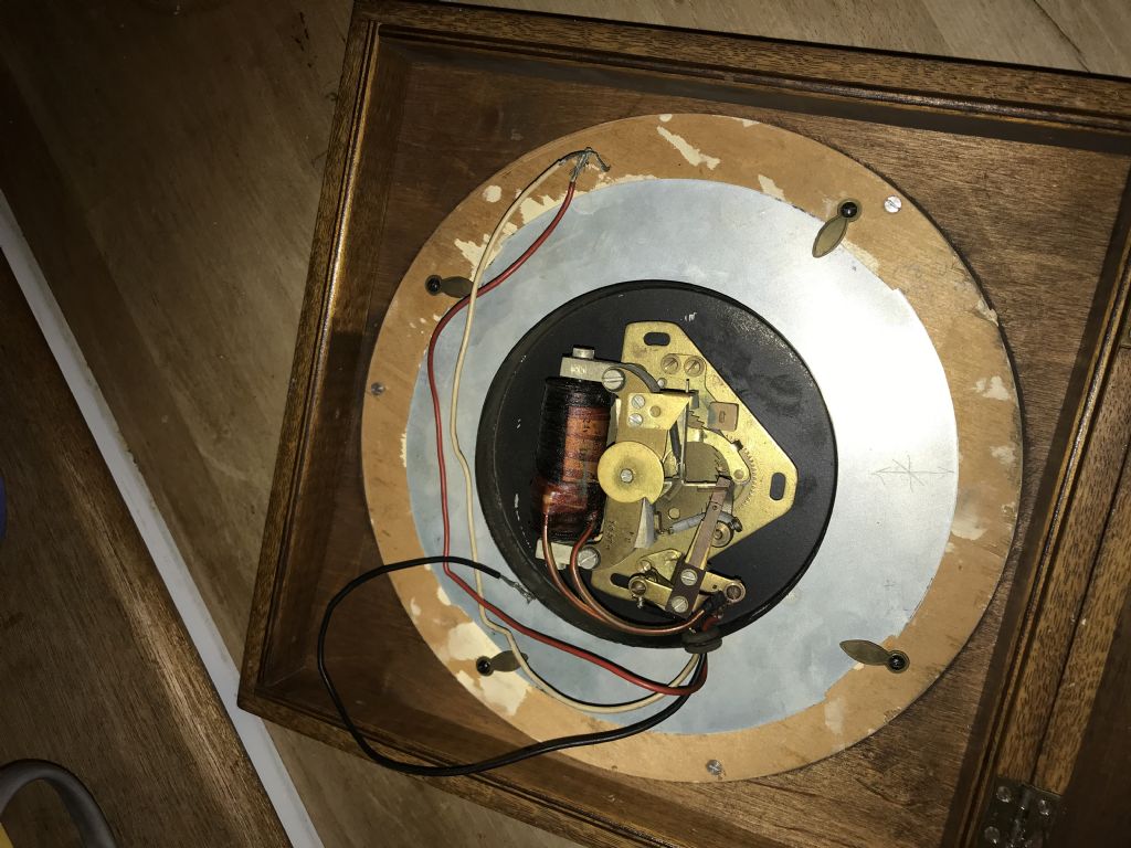
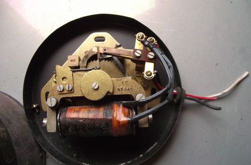
There are two basic variations in synchronous systems, ’wired’ & ‘electronic’. In a wired system, the secondary clocks are ‘hard-wired’ to the master clock with their own network of wiring. This dedicated wiring consists of 3 wires & requires that all secondary clocks be connected to this network in order to receive corrections from the master clock. These systems are usually 110 volts but some are 24 volts. The master clock energizes the third wire to apply voltage to the correction solenoids (called ‘clutch magnets’ by the manufacturer) in the secondary clocks.
In an ‘electronic’ system, the correction impulse is applied to the normal building wiring, in the form of a high-frequency audio signal (typically 3510 hz) applied to the normal 60 hz frequency of the electrical system. Special receivers in the secondary clocks receive this impulse & apply voltage to the correction solenoid. In this type system, secondary clocks need no special wiring & may be plugged into any 110 volt outlet in the building.
The cycle can also be initiated manually for testing & adjustment as follows:
With clock running, rotate 90 degrees to the right, so that the ‘9’ is at the top. Hold in this position approximately 8 seconds (you may hear a clicking sound during this time), then return the clock to it’s normal upright position. Within 60 seconds, the hands will slowly advance to the next hour as described below in the third paragraph ** under ‘Hourly Correction’.
The actual correction that follows is the same in both types of systems. The only difference (described above) is the method by which the correction solenoid is energized.
Hourly Correction
The correction impulse is issued by the system master clock at 57 minutes 54 seconds after each hour & lasts for 8 seconds (until 58 minutes 02 seconds). The correction solenoids in the secondary clocks are energized by this pulse. This causes the attached armature & cam to engage a gear & rotate upwards to lift a latch allowing the correction cycle to begin. This takes 6 seconds & causes the secondary clocks to begin their correction cycle at precisely 58 minutes 0 seconds.
The correction cycle lasts precisely 60 seconds, ending at 59 minutes 0 seconds at which time, all clocks in the system will display the same time as the master clock.
** The cycle causes an internal clock-wise sweep, beginning at the 59 minute position & takes 60 seconds, rotating around the dial, ending at the 59 minute position. During this sweep, if the minute hand is not in proper position, when the sweep rotation reaches it, the minute hand is slowly rotated at 1 rpm until it reaches the 59 minute mark. At this point it is now in sync with the master clock.
During the cycle, the red second hand continues its normal 1 rpm motion but is held in place when it reaches the 60 second mark. It is released when the cycle is complete (minute hand reaches 59 minutes) & now minutes & seconds are both in sync with the master clock.
12 Hour Correction
This impulse is issued by the system master clock at 5:57:54 AM & PM & is a longer version of the hourly correction impulse. Instead of lasting 8 seconds, this impulse is of 14 seconds duration, lasting until 58 minutes, 08 seconds. The cams in the secondary clocks are rotated further & lock the correction cycle latch open, causing the cycle to continue until the clocks reach 5:59:00. Depending on how many hours the secondary clocks were slow, they will now be several minutes slower than the master. This error is then corrected by the next normal hourly correction at 6:57:54.
IF I read Tom's description correctly, the clock gets 110VAC at 60Hz on the red and black wire and runs on the 60Hz signal. I believe that the mechanical version gets the signal from the master clock, not from the mains. (Unlike the electronic version.) In both cases remote clocks are periodically synchonised with the master by pulsing the white wire (once per hour, resync every 12 hours.)
Looks like a good job for an Arduino and some simple electronics. A GPS reference module would make time keeping much more accurate than the original.
Dave
SillyOldDuffer.


