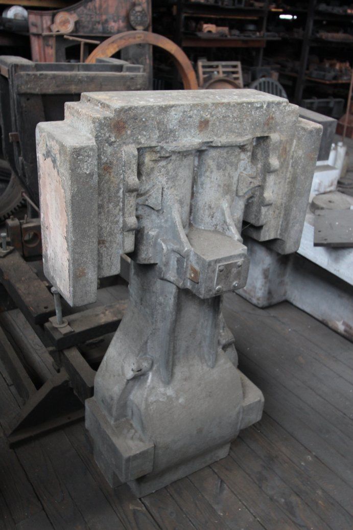
What does your casting setup look like, and results?

Advert

What does your casting setup look like, and results?

Home Forums Workshop Techniques What does your casting setup look like, and results?

Viewing 12 posts - 26 through 37 (of 37 total)
  • Author
    Posts
  • #604402
    PatJ
    Participant
      @patj87806

      I originally set up some calcuations for spure, runner, and gate sizes, and thought I was accomplishing something.

      When I studied a number of old commercial patterns, I found the runner and gate configuration varied widely, and yet all of the patterns I saw had been successfully used to create thousands of engines.

      I was very confused about the sprue/runners/gates/risers until I ran across Bob Puhakka's explanation of how he sets up his casting system.

      I don't calculate anything anymore, and that does not cause problems.

      I basically use a sprue that generally 3/4" in diameter, or sometimes 1" diameter, tapered.

      I use a smooth curved transition into one or two V-shaped runners that are generously sized, perhaps 3/4" tall, 1/2" wide at the top, and 3/8" wide at the bottom.

      The runners extend from the base of the sprue to a spin trap at the end of each runner.

      A spin trap is just a straight vertical hole, perhaps 1" in diameter, and the runner enters the spin trap on a tangent point. The spin traps extend upwards and out the top of the cope.

      I don't use filters.

      I use one or more thin wide gates located on the top of the runners, approximately 1/2" wide, and about 1/8" deep, and that size varies a bit depending on the size of the casting.

      My system uses the gates to control metal velocity.

      I pour directly into the sprue, keeping the lip of the crucible right at the top of the sprue.

      I don't extend the sprue above the top of the cope, but I do use a metal ring about 3/4" tall and about 3" diameter, on top of the mold at the sprue, as a sort of pour basin.

      The sprue is filled as fast as possible, and then kept full for the entire mold fill.

      The initial aspriated air, slag, loose sand, etc. is swept down the runners and into the spin traps.

      The spin traps prevent any sudden kickback in pressure, which would cause metal to be ejected violently into the mold cavity.

      The generous runners fill first, and the cooler front of metal is swept into the spin traps.

      Once the level of metal rises to the top of the runners, the entire runner system is full of hot metal, and the mold begins to fill. The gates act to control flow to yeild an even laminar fill of the mold with no splashing.

      The gates also do a final skim of the slag off of the top of the iron.

      The high spots on the top of the mold are vented, since resin-bound sand does not vent well due it its lack of porosity.

      Occasionally I use a riser if there is a thick part of the casting, to prevent a thinner part of the casting from drawing from the thicker part during metal solidification.

      The iron casting remains in the mold for 24 hours, or until completely cool, so as to prevent chills (hard spots) in the metal. No annealing is required. The iron will be easy to machine and drill. For castings thinner than about 3/4", I use a slight amount of ferrosilicon 75%.

      So far, this method has worked every time I have used it for every iron casting of any shape, and has produced defect-free gray iron castings repeatedly.

      I never have to re-cast anything.

      I generally use two runners, one on each side of a pattern, and gates on opposite sides of the pattern, so as to reduce the fill travel distance inside the mold by 1/2.

      .

      Edited By PatJ on 05/07/2022 16:25:14

      Advert
      #604404
      Luker
      Participant
        @luker
        Posted by PatJ on 05/07/2022 16:18:01:

        I originally set up some calcuations for spure, runner, and gate sizes, and thought I was accomplishing something.

        When I studied a number of old commercial patterns, I found the runner and gate configuration varied widely, and yet all of the patterns I saw had been successfully used to create thousands of engines.

        I was very confused about the sprue/runners/gates/risers until I ran across Bob Puhakka's explanation of how he sets up his casting system.

        I don't calculate anything anymore, and that does not cause problems.

        I basically use a sprue that generally 3/4" in diameter, or sometimes 1" diameter, tapered.

        Edited By PatJ on 05/07/2022 16:25:14

        Pat you need to be careful to mention this is case specific. With phenolics or resin binders the mould is considered rigid which contains the expansion phase with cast iron, then with most of our size castings risers aren't needed and the ingates aren't that important. With moulds that 'give a little' like green sand you need to be careful with the ingates and risers because the sand doesn't contain the expansion, and there is seldom enough in the sprue to feed. Besides if you start casting components with a larger casting modulus (large volume to surface area ratio) you might need to revisit riser design…

        #604415
        PatJ
        Participant
          @patj87806

          Luker-

          I can't begin to pretend that I know enough to even speculate on what is or is not specific to which case.

          Best I can do it state what works for me with bound sand.

          I can't really explain why exactly my setup works, other than it controls velocity via the gates, and not by using a filter, and not by controlling flow via the sprue diameter, and this is bascially per Bob Puhakka's recommendations.

          As far as green sand molds, I can only compare the old commercial matchplate configurations that I have seen, and that gating/runner/sprue/riser has never been consistent from company to company.

          "Larger casting modulus"………you are way over my head I am afraid; I am lucky to be able to spell that.

          I do agree though with what I think you are getting at, which is bound sand configurations may or may not be appropriate for green sand configurations.

          The good thing about bound sand molds is that they do not wash; ie: they don't break off corners, or wash out due to metal flow.

          I can only describe what methods I use.

          It is up to others to determine if that is appropriate for their use.

          I have yet to see two mold configurations be very much alike, and it seems that a variety of methods work.

          And as I mentioned, posting methods on an open forum is an eye-opening experience, which is why I do it.

          I always learn a great deal from the variety of methods and all the comments I receive, and what an excellent opportunity to learn new things.

          Every day is a learning day for me, for sure.

          .

          Edited By PatJ on 05/07/2022 18:35:30

          #604425
          noel shelley
          Participant
            @noelshelley55608

            The split pipe trick for cores makes life easy, I tend to use copper pipe and hose clips, done just tight enough to hold, you slide them off and the pipe springs open and the core slides out, I've not tried it but I think the resin coated sand would work if you heated the pipe..Noel.

            #604437
            PatJ
            Participant
              @patj87806

              Noel-

              There are several types of bound sand, and the binder can be sodium silicate, resin of some type.

              The resin system I use is sort of like an epoxy system, with a resin and a hardener. With the binder I use, there is also a catalyst to control the set speed.

              The old school cores were I think sand and linseed oil, which were baked.

              I have never tried a linseed oil core, but would like to try that one day.

              As I research it, the "resin" in the coated sand you refer to is like a Bakelite product, which is "a thermosetting phenol formaldehyde resin"? Is this true?

              So is it correct to say that resin-coated sand is sand mixed with powdered plastic, and the application of heat to the die melts the plastic and sand into a rigid mold?

              Or is there some sort of dynamic reaction between two or more components like my resin-binder, that sets like epoxy?

              Where does one get resin-coated sand? Is that something one can make at home?

              The more I learn, the less it seems that I know.

              .

              Edited By PatJ on 05/07/2022 20:32:03

              #604440
              JasonB
              Moderator
                @jasonb

                Pat I would say a lot of commercial foundries didn't/don't use core boxes for simple plain cores so it's not something everyone does. Even back in the day a simple extruder would have been used, bit more high tech these days.

                #604446
                PatJ
                Participant
                  @patj87806

                  Just when you think you have seen it all. I thought the Play-Doo extruder was a modern creation.

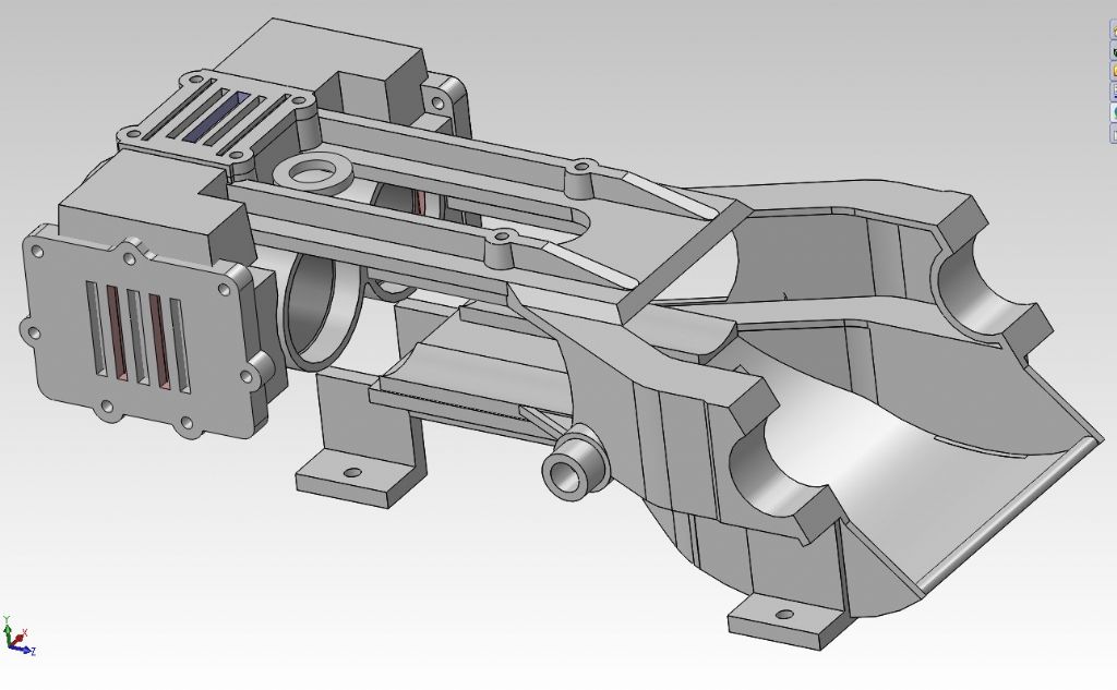
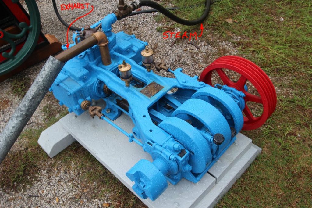
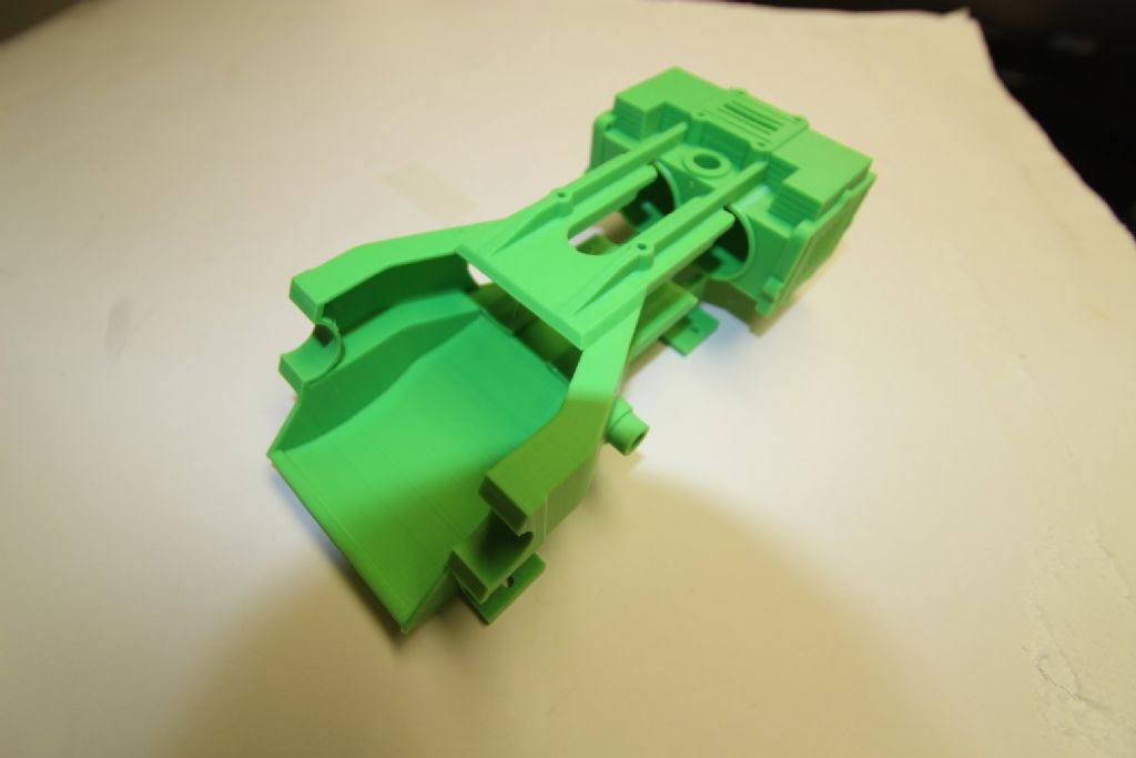
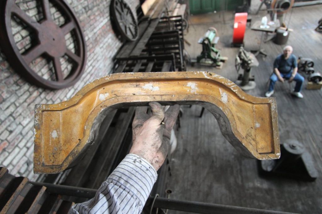
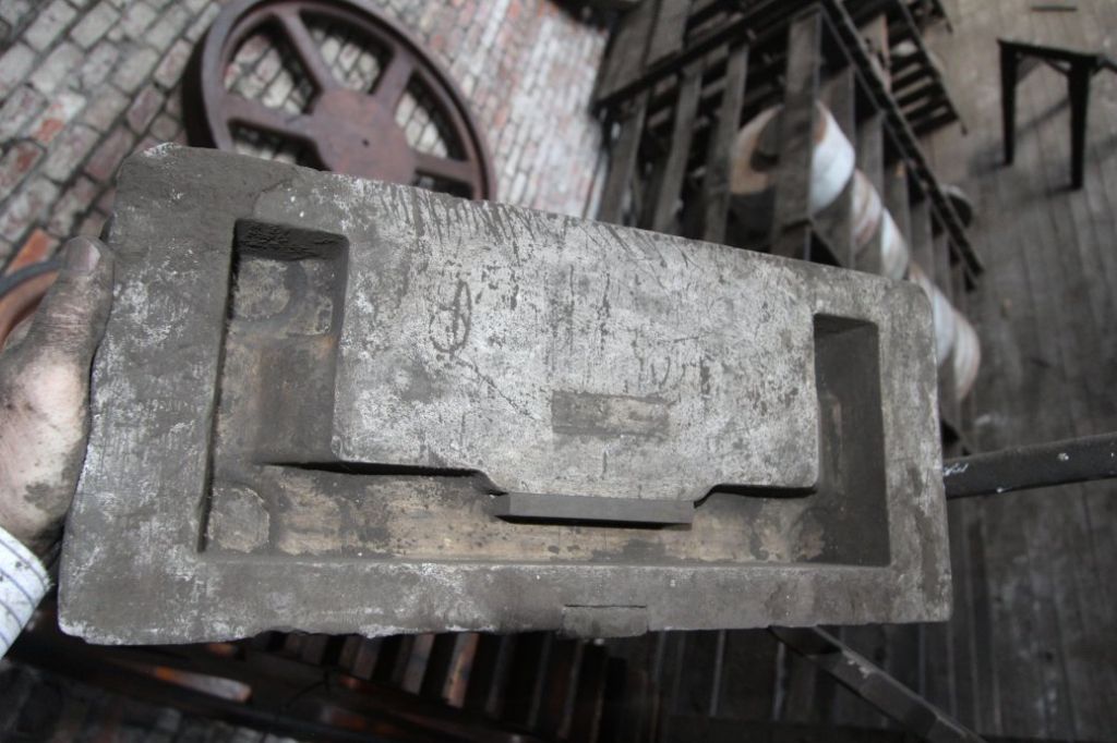
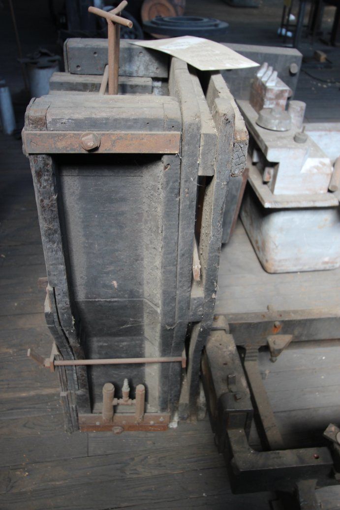
                  I found a lot of the matchplates for the Speedy Twin steam engine at the Soule Museum, but nobody knew anything about the coreboxes for the complex passages that are at the top of the engine.

                  The allowed me to search through the multitude of patterns in the pattern room, and I finally found one of the passage core boxes.

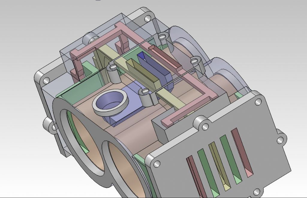
                  The corebox below would be for the beige passage shown in my 3D model.


                  image11.jpg

                  img_1923-rev-02.jpg

                  rimg_3154.jpg

                  rimg_3923.jpg

                  rimg_3926.jpg

                  speedy-twin-screen-cap-01.jpg

                  Edited By PatJ on 05/07/2022 22:08:04

                  #604448
                  PatJ
                  Participant
                    @patj87806

                    This is the horizontal part of the red passage in my 3D model above, and as you can see, it is quite a bit larger than I modeled it.

                    Its fascinating to find the actual patterns and core boxes for an old steam engine.


                    rimg_3951.jpg

                    Edited By PatJ on 05/07/2022 22:16:25

                    #604450
                    PatJ
                    Participant
                      @patj87806

                      This is the original Speedy Twin frame corebox.

                      rimg_3872.jpg

                      rimg_3875.jpg

                      rimg_3876.jpg

                      rimg_3970.jpg

                      #604455
                      PatJ
                      Participant
                        @patj87806

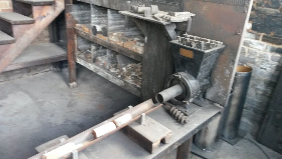
                        And low and behold, here is an extruder at the Soule factory.

                        I don't think I ever noticed it in the photos or in person, but now that Jason pointed one out, there it is !

                        r20160521_125949.jpg

                        Edited By PatJ on 05/07/2022 22:31:47

                        Edited By PatJ on 05/07/2022 22:32:04

                        #604456
                        PatJ
                        Participant
                          @patj87806

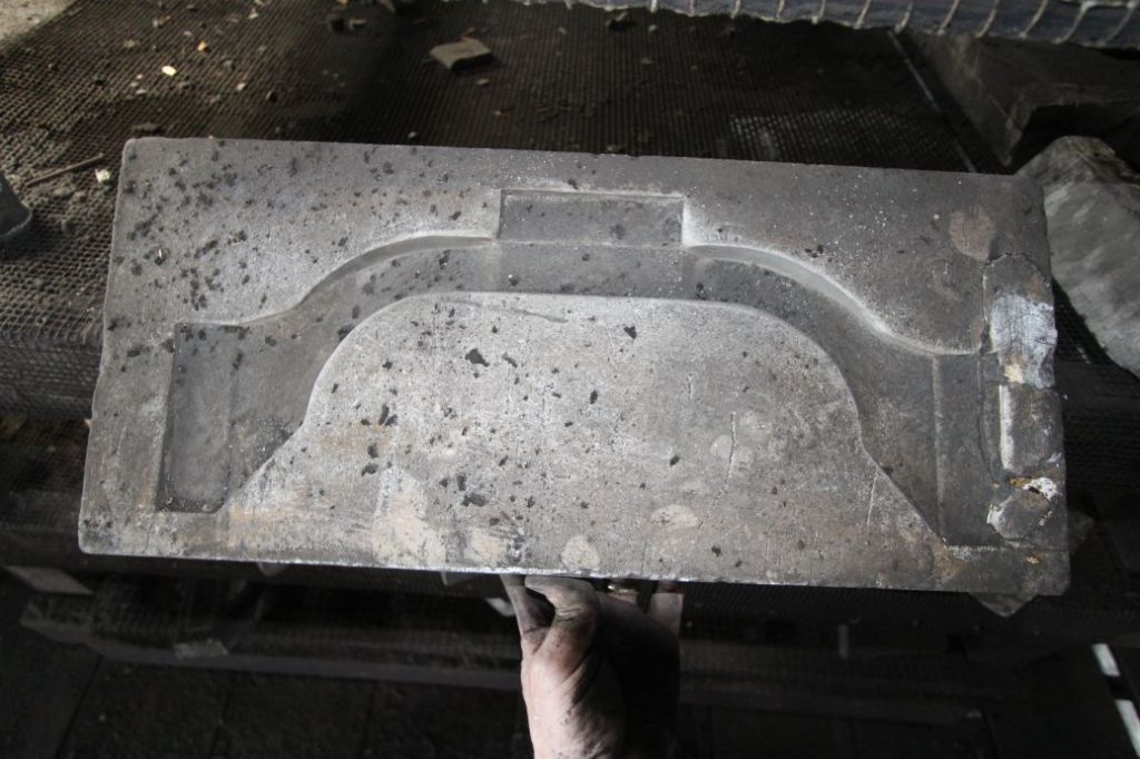
                          Here is the Speedy Twin frame pattern, with multiple coreprints.

                          rimg_2155.jpg

                          Edited By PatJ on 05/07/2022 22:33:02

                          #604466
                          noel shelley
                          Participant
                            @noelshelley55608

                            You use the sand straight out of the bag, so It's thermosetting.. I dont know where it comes from or what it's called I bought a sack when I last worked for ST. For steam passages it is ideal. Noel.

                          Viewing 12 posts - 26 through 37 (of 37 total)
                          • Please log in to reply to this topic. Registering is free and easy using the links on the menu at the top of this page.

                          Advert

                          Latest Replies

                          Home Forums Workshop Techniques Topics

                          Viewing 25 topics - 1 through 25 (of 25 total)
                          Viewing 25 topics - 1 through 25 (of 25 total)

                          View full reply list.

                          Advert

                          Newsletter Sign-up