What Did You Do Today 2021

Advert

What Did You Do Today 2021

Home Forums The Tea Room What Did You Do Today 2021

Viewing 25 posts - 326 through 350 (of 480 total)
  • Author
    Posts
  • #561836
    Dalboy
    Participant
      @dalboy

      Still working on the new workshop nearly finished the major work except the electrics. At least I will be able to start moving back in soon

      Advert
      #562195
      Anonymous

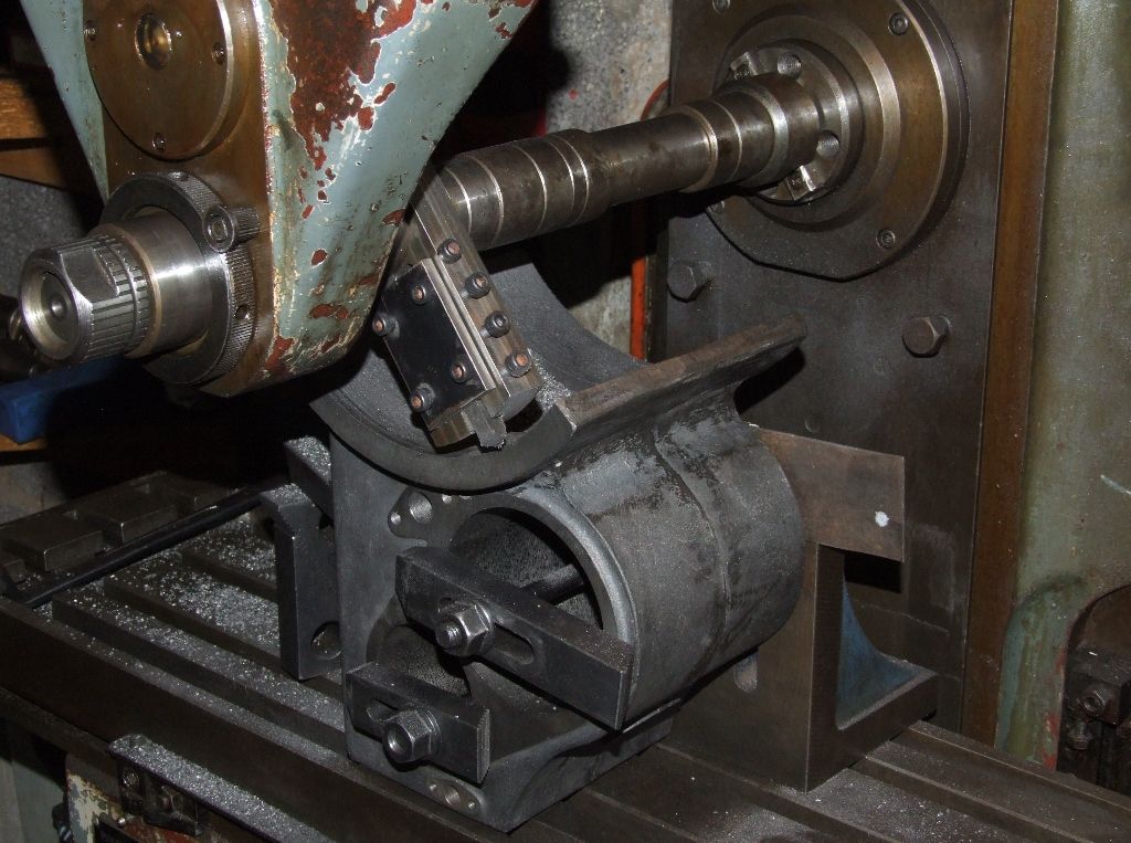
        Finally got around to machining the underside of the flanges on my traction engine cylinders:

        cylinder_flange_me.jpg

        The piece of steel sheet against the angle plate is to tilt the cylinder slightly so that the vertical centreline of the pistons lines up with the crankshaft. In the CAD model the angle is 0.64°, but I settled for anywhere between 0.6° and 0.7° on the digital angle gauge. The backward tilt of the cylinder mimics that of the full size engines, where the designer presumably ran into the same problem of things not lining up.

        Roughing cuts were 40 to 50 thou deep and 10 to 15 thou feed per rev at 54rpm. On the finish cut feed was reduced to 4 thou per rev, which took for ever feeding by hand.

        Fortunately when mounted on the engines both cylinders slope back by 0.6° indicated and the measured distance from flange to top of the cylinders is within a couple of thou of the CAD model value of 8.07". So there's no excuse for everything not lining up.

        Andrew

        #562292
        Bazyle
        Participant
          @bazyle

          EDMES had it's delayed AGM today and just managed to get a forum of 15 members to comply with the constitution and elect a new Chairman ( who is in Corfu at the moment).
          We also had about 15 members at the SADMES meeting on Wednesday.

          Good that people are getting back into the groove

          #562499
          Nicholas Farr
          Participant
            @nicholasfarr14254

            Hi, yesterday afternoon I set about up-cycling some scrap pieces of metal to make a step-up, which is about 230mm high, the tread is a chequered aluminium stair tread, which I made a couple of flat pieces of 40 x 6mm flat black bar and drilled a couple of holes in each end to match the holes that originally fix the tread into place and 10mm nuts were welded onto one side of these plates where the holes were drilled. Four legs are from some tables that had castors attached, of which I had to shorten down in my last day job and these where much to useful to bung in the scrape bin, so I acquired consent to take them home. (I think there were about eight tables that I had to alter, giving me 32 of these legs some of which I've used for a couple of other jobs)

            step-up#1.jpg

            step-up#2.jpg

            Two legs were set-up at one end of each of the plates and piece of 20 x 20 x 2mm SHS was cut to fit between the two as a tie-bar and was also set-up. These were then all tack-welded into place.

            step-up#3.jpg

            The other two legs and another piece of SHS were then set-up in the same manner and tack-welded into place and then two shorter pieces of SHS were cut and set-up and tack-welded into place between front and back legs. All four of these legs were picked from the selection that I have, so that my tie-bars could be weld in the same place as the tie-bars were on the original tables.

            step-up#4.jpg

            step-up#5.jpg

            Hoping the weather is OK tomorrow, I can then weld all the joints up and then look to see if I can reverse the up-turn of the tread to a down-turn to match the one which can be seen at the front in the above photo.

            Regards Nick.

            Edited By Nicholas Farr on 12/09/2021 14:44:36

            #562548
            Dr_GMJN
            Participant
              @dr_gmjn

              I can’t find a specific forum for this, but today I visited Wortley Top Forge, just north of Sheffield. It’s only a 15 minute drive for us. I went many many years ago, but it never really registered in my memory as a child. However, a work colleague went recently, and told me it was good.

              I went with the kids (11 and 13), and it was great. Loads of what I’d describe as small to medium sized steam and internal combustion engines, workshops with belt driven machines, a forge, water wheels, small steam railway, etc etc. The amazing thing is that most of it works (steam engines mostly on compressed air), and how accessible everything is. On arrival we immediately got befriended by a volunteer, who began to show us various engines, gave us a demonstration of ‘barring’ a steam engine, before passing us on to someone else who gave us a full tour of the rest of the place. The water wheels work, and drive a trip hammer and a crank driven furnace blower. There was also a tour of a typical 19th century worker’s cottage. We will definitely go back when we have more time, hopefully when there’s an en event in where they have live steam exhibits.

              Entry was £3 for adults, 50p for kids. Quite an amazing place all in all. I wish I’d gone again before now.

              Here are some random images:

              Loads more than in the photos. Proper museum with proper volunteers; we learned stuff about social history, metallurgy and engineering. We all thought it was brilliant.

              #562566
              Nigel Graham 2
              Participant
                @nigelgraham2

                Thank you for the photos etc of Wortly Top Forge , Bazyle. That lathe has some very fresh-looking swarf in the buicket under it!

                I do like these smaller, volunteer-run industrial museums as they lack the pickled-in-aspic-and-ignorance feel of one or two of the Big-Name places I have seen.

                If you are Down South, in Somerset, Weston Zoyland Pumping Station Trust's work is worth seeing – and it does run its engines on steam, supplied by a large Portable Engine uinder an adjacent lean-to. Pride of place is its original, in-situ, Amos engine and centrifugal pump. The site was originally for fen-land drainage, on the Somerset Levels; and the modern pumping-station (not publicly accessible) is adjacent to the museum.

                Though only open occasionally, there is an intriguing small-scale water-works museum just outside Sherborne (N. Dorset). The water-supply pumps were water-wheel powered and have been partially rebuilt to show this; but the museum also has a fine Hindley mill-engine rescued from another water pumping-station in the area, and run from a vertical boiler. The point this museum emphasises is the site's role in fighting the water-borne enteric diseases, especially cholera, that were as rife in small rural towns as in the the Dickensian, East End of London.

                SE Dorset has its famous Corfe Castle ruins overlooking the restored Swanage Railway with its new, SR-trim, Norden Station serving a Dorset Council run park-and-ride. Between car-park and station is a small museum devoted to the local ball-clay mining, with a short represantative level. The site itself was not a clay-pit but was instead the transhipment point to the national railways for clay brought there by various narrow-gauge railways from pits in the surrounding countryside, and the museum's short 2ft-g. railway gives a somewhat limited and unfortunately not emphasised flavour of this.

                While for the military-minded, Bovington Tank Museum is not ever so far from there.

                ++++

                Me Today?

                With Thanks to my appeal on the Wanted Classifieds –

                I started sorting out the pre-loved gearbox I bought, err, a while ago, for my Myford ML7. I found the parts I feared lost, and identified the gears therein.

                These included the output-side idler with several teeth missing (appropriate for me… ask my dentist!); and a brand-new stock gear I assumed the seller had intended modifying as its replacement.

                So last thing this evening I made a split-collet from an oddment of aluminium scaffold-tube, for holding that wheel in the 4-jaw independent chuck.

                Prior to closing up for the night and ensuring the cask ale in my local is up the scratch. It was.

                Setting the wheel central and boring through for a bronze or 'Oilite' bush is the next task.

                #562589
                Robin
                Participant
                  @robin

                  Yesterday I turned off everything in the workshop, shut down my computers and went with my son and my granddaughter, aged 6, to Chessington World of Adventures where I spent lots of money. Best day ever smiley

                  #562697
                  Nicholas Farr
                  Participant
                    @nicholasfarr14254

                    Hi, welded and cleaned up my step-up frame ready for painting.

                    step-up#6.jpg

                    Regards Nick.

                    #562705
                    Nigel Graham 2
                    Participant
                      @nigelgraham2

                      Thanked the two Forum users who had responded to my appeal for help with a Myford screw-cutting gearbox.

                      It didn't seem to match the details they sent, but a bit more research via lathes.co revealed the unit is an early version – though in very good condition! Still, the lathe itself is of 1947 vintage, so that's appropriate I suppose.

                      I was intending to machine the replacement idler-gear for the output side, but instead made and used the drilling & tapping template for the two screw-holes needed in the lathe's bed for fitting the gear-box; and spent a bit of time becoming further acquainted with the thing.

                      #562706
                      Bazyle
                      Participant
                        @bazyle

                        Well I'm puzzled why Nigel has thanked me for Dr_G's photos of Wortley Top Forge. Though I have mentioned the model engineers there after I visited years ago it was just after they had been flooded right up to the level of the signal box. it is so long ago I can't find the postings or photos. Might be before I had a digital camera.
                        It is interesting to reflect that when you see a very old railway wagon in some museum it's axles were probably made on those self same trip hammers, still working and ready to make some more 150years later.

                        #562709
                        Michael Gilligan
                        Participant
                          @michaelgilligan61133
                          Posted by Bazyle on 13/09/2021 23:44:02:

                          Well I'm puzzled why Nigel has thanked me for Dr_G's photos of Wortley Top Forge.

                          .

                          A simple error of punctuation, methinks

                          MichaelG.

                          #562711
                          Paul Lousick
                          Participant
                            @paullousick59116

                            The first thing which intrigued me in Dr_G's post was the first photo of what appears to be a variable speed drive. The same principle was used (and still is) for speed control of mechanical equipment.

                            I remember using "Reeves" Vari-speed drives in the early 1970's. Some of the latest small cars use a CVT gearbox (constantly variable transmission).

                            The speed of the output shaf depends on the diameters of the pulleys. The flanges of the pulleys are tapered and the belt does not run on the bottom of the pulley but on the sides of the taper. The distance between the flanges is variable and because of the taper, the diameter of the pully where the belt is driven changes in diameter, altering the ratio between the 2 pulleys.  I presume the red lever alters the width of the controlling pulley. The flanges of the second pulley are spring loaded and automatically compensates.  Speed adjustments are only done when the drive is running.

                            vari speed drive.jpg,

                            Edited By Paul Lousick on 14/09/2021 00:56:22

                            #562718
                            Nicholas Farr
                            Participant
                              @nicholasfarr14254

                              Hi Paul, that's what I presumed it is, there was one that drove a 6M filter table where I used to work years ago, but it wasn't as heavy as the one shown, it had a 50 x 16mm belt, which looked a bit like a very wide flat "V" belt. I can't remember exactly how the belt was changed, but I think it had to have the driving pulley partly dismantled and I only changed it a couple of times in the 36 years I worked there, but it would last quite a few years between changes. It was quite a tough belt but it would lose its shape, which meant it was hard to keep a constant speed on the table.

                              Regards Nick.

                              #562730
                              Paul Lousick
                              Participant
                                @paullousick59116

                                The modern industrial vari-speed belts are like you have said, a wide vee belt, made from a similar, reinforced rubber material. A bit different to the one in the photo with wooden links attached to a flat belt. And different to the belts in the new car CVT drives which are made of thousands of metal parts.

                                A friend wanted to buy a new car with one of the new transmissions and I did a bit of research and discovered that the belts push to transmit power and not pull like traditional belts. They are very compact compared to a tradition gearbox and although the makers claimed that they were reliable and good for 100,000 plus kms, found that they had a few problems, especially if driven hard and rccommended not to buy one.

                                #562731
                                john fletcher 1
                                Participant
                                  @johnfletcher1

                                  Nigel regarding early Myford gear box, I had one and fitted it to a lathe about 20 years ago. I think I had to shim the G/box mounting away from the bed to get correct alignment of the lead screw. Also I found much to my dismay several gears with teeth missing, I bough gears from HPC at Chesterfield which I had to sleeve. Took some time, but work out OK in the end. John

                                  #562740
                                  Dr_GMJN
                                  Participant
                                    @dr_gmjn
                                    Posted by Paul Lousick on 14/09/2021 00:30:22:

                                    The first thing which intrigued me in Dr_G's post was the first photo of what appears to be a variable speed drive. The same principle was used (and still is) for speed control of mechanical equipment.

                                    I remember using "Reeves" Vari-speed drives in the early 1970's. Some of the latest small cars use a CVT gearbox (constantly variable transmission).

                                    The speed of the output shaf depends on the diameters of the pulleys. The flanges of the pulleys are tapered and the belt does not run on the bottom of the pulley but on the sides of the taper. The distance between the flanges is variable and because of the taper, the diameter of the pully where the belt is driven changes in diameter, altering the ratio between the 2 pulleys. I presume the red lever alters the width of the controlling pulley. The flanges of the second pulley are spring loaded and automatically compensates. Speed adjustments are only done when the drive is running.

                                    vari speed drive.jpg,

                                    Edited By Paul Lousick on 14/09/2021 00:56:22

                                    That was one of the first things I saw. I was intrigued as well, and asked if it was some kind of CVT. To my amazement I was told it was – I though they were a mid-20th century invention (DAF Variomatic was one I think?). Perhaps they’ll have it running at the next open day.

                                    #562752
                                    Mike Hurley
                                    Participant
                                      @mikehurley60381

                                      DAF Variomatic – correct (unkindley often referred to as ' the one with the rubber-band drive' ) I also used a Raglan lathe for many years having a similar system – was very good to use.

                                      What constantly surprises me with this sort of thing is that there always seems to be someone who's thought of it before! .

                                      #562785
                                      Terry B
                                      Participant
                                        @terryb

                                        Robert Boby Seed Cleaning Machines made in Bury St Edmunds until the 1960s had a variable speed on the drive for the winnowing fan that looked identical to the one shown . When you turned the adjusting wheel the bar shown connecting the two pulleys pivoted and moved one pulley disc out simultaneously moving the other in thereby varying the speed.

                                        #562829
                                        Nicholas Farr
                                        Participant
                                          @nicholasfarr14254

                                          Hi, today I managed to flatten the up-turn of the tread of my step-up and fold the downward, but I had to anneal it four times in all, three times to flatten it and one to complete the fold.

                                          step-up#7.jpg

                                          It took about eight minutes to get it to about 700 C with my big propane torch each time.

                                          It was then cleaned and fitted and is now ready for use.

                                          step-up#8.jpg

                                          Regards Nick.

                                          #562833
                                          bernard towers
                                          Participant
                                            @bernardtowers37738

                                            85ee93f8-c769-4b78-8152-363fa1f0c46d.jpegNow student is up and running done a bit on the wallaby cyl23b62aba-8ed9-418e-8bfc-1e8f7c0f1115.jpeg head today

                                            #562945
                                            Neil Wyatt
                                            Moderator
                                              @neilwyatt

                                              My waterproofing of the garage goes slowly.

                                              After curing three more small roof leaks, it turned out that the raised concrete sill of the door had detached from the concrete slab underneath.

                                              Putting in a proper gutter had helped a lot, but water was still getting in.

                                              Yesterday, after discussing with my brother, I lifted it then drilled a row of shallow holes with a 1" masonry bit, following up with a smaller hole, plug and an outdoor rated screw left 3/4" proud. Meanwhile he brought over some left over postcrete which I used as readymix to create a new sill.

                                              Fingers crossed.

                                              Today I managed to move an old bench my dad is emotionally attached to (I'm tempted to physically attach him to it, but that's another story… ). I had to add long 3×2 extensions to three of the legs to make up for rot and an uneven floor.

                                              Tomorrow a run to the tip with several bags of rotting wood, rust and general purpose 'yuk'. Thank heaven for PU coated reinforced gloves!

                                              #562951
                                              Nicholas Farr
                                              Participant
                                                @nicholasfarr14254

                                                Hi Neil, talking about door sills takes me back to 1982 when I moved into a fairly old house and after being there for a while, I had to look at why the floor just inside the front door was a bit springy, turned out the ends of the joists were rotten just behind the sill. The sill was fair well worn and the water bar had rusted badly letting the rain in. The sill, which is more of a step, was a concreate cast and really wasn't repairable, so after cutting back and replacing the joist, I set to and made a plywood mould and fitted in a stainless steel water bar, the step had a slight slop downward away from the bar and a rounded corner on the outside, plus a semi-circular groove on the underside to prevent water running back on to the brickwork it sat on. I mixed up some sand and cement and a load of those small stone chippings that you get in paving slabs and cast it into my mould with a bit of some inch square mesh for reinforcing which I tack weld to the water bar, might have been a bit overkill, but it turn out and fitted just fine and although I might be blowing my own Trumpet, it really did look like a proper job.

                                                Regards Nick.

                                                #563253
                                                Bazyle
                                                Participant
                                                  @bazyle

                                                  The Shoutathon returned after giving it a miss last year. I wasn't aware for years when working in the office but every year the local comprehensive school, sorry, College now, set off on a 6 mile charity walk which takes them though our village. Blissfully unaware I had taken the last dry day of the year off to do some gardening. All 1500-2000 of the little darlings take a break for half an hour just outside my house to practice shouting it seems. they were lucky with the weather with a breeze after several still days but tomorrow brings all day rain.

                                                  #563263
                                                  Nigel Graham 2
                                                  Participant
                                                    @nigelgraham2

                                                    A very pleasant lunch out with a couple I have know for years but had not seen for the last 3, even 4, I think!

                                                    Then back to carry on persuading my 1947-born ML7 to accept an early-pattern QC thread-cutting gearbox – I had bought both some years apart, from different sellers.

                                                    This with help from respondents via e-post to my appeal recently on here for information. I soon found that Mydord had changed the gearbox design significantly quite early on, and the information from the fellow forum users was for the later pattern. Still, their help gave me a start and as well as the mechanical work I've now bought a manual covering both, from lathes.co, and ordered the appropriate top-end driving-pinion from Myford.

                                                    I had feared they would not have them, but the gentleman was very helpful and between us we identified the right part number and my bank-card number. I demurred at the cost of a leadscrew though – I don't want to take the fateful step of cutting the existing if at some point all else fails. My thought now is to buy a length of appropriate stock ACME bar and make the short one necessary; keeping the original and associated swapped parts carefully as reversion-spares.

                                                    That pinion is very particular, a tiny 12T thing. The later box of cogs uses a more robust 24T wheel, already in my collection, but of course that doubles all the pitches selected on the controls.

                                                    So I created an 'Excel' spreadsheet of possible Imperial threads and close-match metric ones with the 12T, 24T and other change-wheels up to the maximum I found would fit – 50T – as driver "pinion". The early gearbox quadrant holds two wheel-pairs on fixed centres giving a high and low range, somewhat limiting it. Nevertheless it still offers all the threads I am likely to want to cut.

                                                    It's suprising what is theoretically possible by screw-cutting to say, two-thirds depth then correcting by finishing with a die. For most the cumulative error is sensibly low for less than perhaps 10 turns – e.g. studs, tie-bars, piston-rod ends and the like. I based the table on the 24T wheel and its effects on the machine's settings, then used a Tracy Tools thread-chart to identify all the useable settings for BSW/F, Pipe, Brass and ME, and ISO-M Coarse.

                                                    The later QC and quadrant are fully-slotted for an auxiliary change-wheel train hence a vast range of potential threads including accurate metric and BA. It might be possible to extend my quadrant's securing slot just enough to allow a 63T driver – if the spreadsheet shows this will give closer M-series threads than using the 32T wheel.

                                                    #563337
                                                    Neil Wyatt
                                                    Moderator
                                                      @neilwyatt

                                                      Hi Nick, these photos may be of interest.

                                                      The new sill:

                                                      20210917_123742.jpg

                                                      Waterproofing – a sort of cement resin mixture – add water and mix to a thick creamy consistency. You need to mist it a few times as it sets. Really just belt and braces, I'm fairly confident the base of this wall doesn't really leak, but hard to go back once insulation, plasterboard, skirting (and possibly floor) are in place.

                                                      20210917_123734.jpg

                                                      The trusty B&D Hammer drill was rescued from a skip, clogged with gypsum dust, it has done sterling service for donkeys years. Unlike battery drills that seem to have a puny and rapidly wearing out hammer action, the hammer on is as good as new, just as well when drilling 1" holes through walls, even of breeze block.

                                                    Viewing 25 posts - 326 through 350 (of 480 total)
                                                    • Please log in to reply to this topic. Registering is free and easy using the links on the menu at the top of this page.

                                                    Advert

                                                    Latest Replies

                                                    Home Forums The Tea Room Topics

                                                    Viewing 25 topics - 1 through 25 (of 25 total)
                                                    Viewing 25 topics - 1 through 25 (of 25 total)

                                                    View full reply list.

                                                    Advert

                                                    Newsletter Sign-up