Neil, I did say traction engines as in General purpose or agricultural which were used for belt work. Also need to take into account that preserved engines may not be true to original.
The top picture is a road loco and they did not do a lot on the belt so were sometimes painted.
And as you Duke oF Rutland the showmans road loco have a closer look thats not a black painted ring its a nice patina on the CI caused by years of running the generator off the belt.
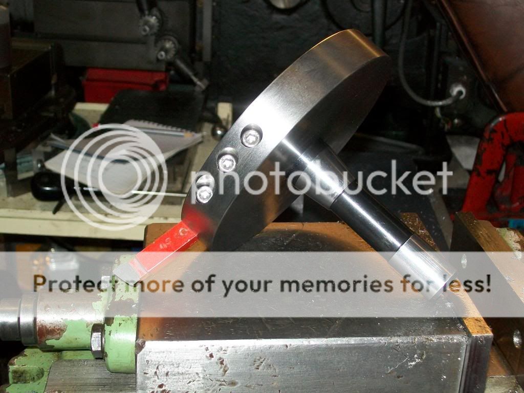
The other thing that may be hard to do if it were ground is to put the crown on the rim, would need some form of copy grinder I suppose.
Well, yesterday really. I posted a thread asking for information on a component I need to make a drawbar extractor that will fit the bizarre thread on my mill drill spindle. By teatime I had been made a generous offer and asked, by a regular contributor, for the dimensions of the proposed extractor as he was "set up" for it and it would save me having to braze a piece in! What an amazing forum this is with even more amazing people contributing to it.
I used a mix of PVA type glue water and drywall compound but polyfilla would do. I'll write it up in the build thread for the E&A on MEM and put a link here when its done, will be a week or so as I need to paint the stone.
I fitted a new loo seat, fitted a curtain rail, shortened a new pair of curtains and eventually got to make a couple of parts for Gray's neat differential leadscrew dial design (the main spindle, less the gear cutting, and the washer).
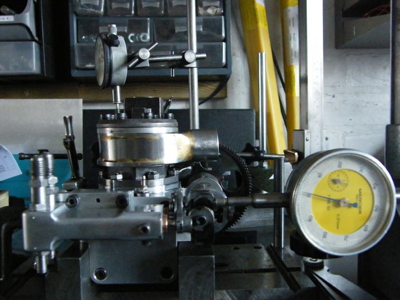
I've never worked to hundredths of a millimetre before – high stress and difficult mental calculations with dials marked in 0.025mm! Much judicious use of emery cloth!
Today I started on converting a warm and well lit home office into a warm and well lit model engineering workshop.
What passes for my current workshop is the end of a draughty and uninsulated garage with very little natural light and the office is very lightly used due to impending retirement. I have done very little in my shop for the last 4 weeks or so since freezing my wossnames off in pursuit of a hobby seemed a bit extreme so casting around for somewhere better suited I lit on the office and the decision seemed to be what our former colonial subjects would call a "no brainer".
There is some electrical work to install power sockets at bench height, a bench to make, which will be a 3 metre long kitchen worktop, and some shelves to put up. After that move the lathe and mill/drill and away we go. Hopefully I should be set up again just in time for Spring!
Hi, well today I found out that I need another 32 tooth change gear for my Boxford to screwcut my new blank backplate. So thats that job on hold till at least Thursday evening.
Set off with the intention of working on the ball turning tool from MEW. Having yesterday compeleted a hand turning rest ( modelled on GHT's version) for my Boxford. . The SWMBO decided , as it was above zero, that the caravan should be cleaned! Four hours later it looked a lot cleaner and most of the muck was on me instead.
Decided instead to sand and oil a 12" Burr oak bowl which I was working on yesterday. Then got carried away and sorted a burr elm bowl (only 5" dia) as well. Still to sand and oil that but retired to computer as needed some inspiration !
Tomorrow may take dogs / kids or combination of the same to Brimham Rocks climbing or might go to York club for Easter steaming- SWMBO permitting!
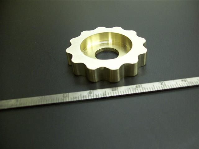
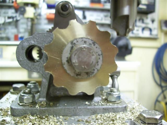
I made this for my clock (see photos) it's an indexing wheel for the hours cylinder. First turned to size,bored out a recess, used a ball end milling cutter to cut the "teeth" then rounded of the tops with a corner rounding cutter. The cylinder will then be held in place by a 8mm o/d ballrace rolling into each "tooth" in turn.
I have the WM16 with the digi readout like yours,& have been have a bit of a prob' correctly using the up / down arrows to set measurement ref. maybe I need to clean mine as there seems to be spurious readings when I try to put a d.o.c. on, would appreciate your tip on how to utilise this reading facility correctly as the manual mentions nothing about its setting?
Did have the intention of having a easter weekend with the grandkids & family, plus replace a rumbling bearing on my 4"x6" bandsaw blade guide; this all went to pot as ma in law (94) took ill with the Norovirus on Fri. To cut a long story short my better half & myself ended catching it too, so kaput went the weekend,obviously the grandkids were upset as they were looking to have plenty of choccies from nanna & great nanna, Should be ok in a couple of days though, Cest la Vie as the adage goes.
My afternoon tug pilot slot today was cancelled, on the grounds that the morning crew tried to get a glider out to the launch point, and promptly got it bogged down in the mud half way there. Yippee, workshop time beckons. I thought I'd make a start on drilling and profiling all the rear spokes for my traction engines on the CNC mill. I fired up the CAM program, created the code, and went into the workshop to set the new tool table, set up a fixture and set the work co-ordinates. I thought I'd better do a quick 'air' cut, just to make sure the drill was going to clear the clamps. First run the spindle starts and then stops. Second time around it never started, although the X, Y and Z axes all moved perfectly each time. What the *****!
Therein followed a close examination of the code and individual G & M codes. All looked fine, and it was consistent with a previous CAM program for drilling that worked perfectly. Conclusion, there's summat wrong in t'mill.
Poking about inside the control cabinet and measuring assorted voltages on the emergency stop lines and contactors according to the troubleshooting guide in the manual didn't raise any issues. Following one of the key rules of circuit debugging I then attempted to break the thing properly by pushing and pulling various bits. Bingo, pushing on some relays on one of the PCBs made the spindle run! Let go and it stopped. Modulate the push force and the spindle speed varied in sympathy. That makes some sort of sense, since the wires on the nearest connector are to do with spindle speed feedback. The crimps on these wires seem ok, taking each one out and giving it a tug, but in my experience with crimps that's not a reliable guide. So most likely I've got some dodgy crimps on the speed feedback, or possibly the PCB itself has a dodgy solder joint or broken track.
The next move is to get some suitable bootlace crimps and remake the said crimps to see if that cures the problem.
Oddly enough I had some speed and spindle issues a couple of months ago, which seemed to be resolved, as I've used the CNC mill quite a lot in the last couple of weeks with no problems. I put the issue down to condensation in the very cold workshop as the spindle seemed to run fine after the machine had been on for a while. It would seem that I might have been wrong.
Last night I suggested taking the dog for a walk, locked the back door behind us and when we got back it wa jammed solid. (This is the other lock from teh one that locked up a year of so ago on the same door!
Today, after much banging, squirting and probing I ended up having to chisel a slot 8" long and 1 1/2" deep in the door jamb so I could flex the frame enough open the door
I can fill the hole with a wood block to restore security and I discovered that chemical metal sticks to uPVC which was a pleasant surprise! Shame it is grey…
As for the lock, it had a big burr on the lock pillar and seems to be very worn. I got it working at last – then dropped the key somewhere under my bench. I think it fell in my car repair toolbox, which is like Hermione's beaded bag – for those familiar with 'Harry Potter and The Deathly Hallows'
That base looks fantastic painted. You make the whiole thing appear infuriatingly simple.
Windy –
4000 psi? I've just been telling my wide about this mad pensioner speed freak – I hope we are able to come and see one of your record attempts when the weather gets better!
Today I looked after my poorly 4 year old, using up a day's precious leave which was planned for other things. But tonight I got out in the back garden before the sun left for the day then I came inside and drew up the plans for my new, first, workshop. 10ft by 10ft square internally so should give me enough room for the Barker, Elliott 10M and Chester Champion and will be a darned sight warmer than the garage I am in now. By next winter I should be metal chewing in the warmth
Hope your youngster has perked up a bit John and that it was nothing serious!
Finished off overhauling and rebushing a Winterhalder and Hofmaier quarter chiming 'ting tang' bracket clock, quite a tussle with the brute because the last joker that had a go at it made a real balls up of it!
They'd fitted pivot bushes and left them overhanging inside and outside the plates, so the oil sinks looked a right old eysore and the inside bits were making the trains bind!
Add to that no oil on anything, which had caused brass from the plates to ball up on the mainspring barrel arbours and train pivots making a right damned mess to clean up!
All's well that ends well though, and it's ticking and chiming away happily keeping company with an Art Deco' garniture clock I finished a couple of days ago ………… starting to drive my missus nuts with all the ticking and chiming going on!
The brass visible on the arbours was actually embedded where metal had been torn out of the surface, the mainsprings on this thing are heavy and don't take prisoners when there's no lubricant on anything!
"Bert Monroe was at Bonneville with a modified Indian. "
Was that the one featured in the film " The Last Indian"? I hired that some years ago and watched it through three times in the week end! My (then) 8year old Grandson was with us on one of the nights and enjoyed it as much as I did.
I knew Bert as a patient in hospital when I was doing my nursing training in Invercargill (down the bottom end of the South Island NZ), Bert's home town. I see that Indian in the USA have built a replica of berts bike with a brand new design engine. Ian S C