Apart from tedious daily job searches I've been digging out and cleaning my old camera gear. One of the older lens' I inherited from my Dad is a Nikkor Auto-S 50mm f/1.4 pre AI which won't ordinarily fit onto modern DSLR's. After some research I found these could be converted by milling part of the aperture index ring and I've successfully done this following directions I found online. It works ok although trying to maintain a steady close focus at f/1.4 is a bit of a challenge.
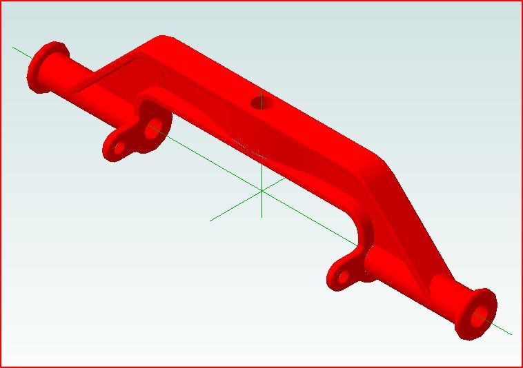
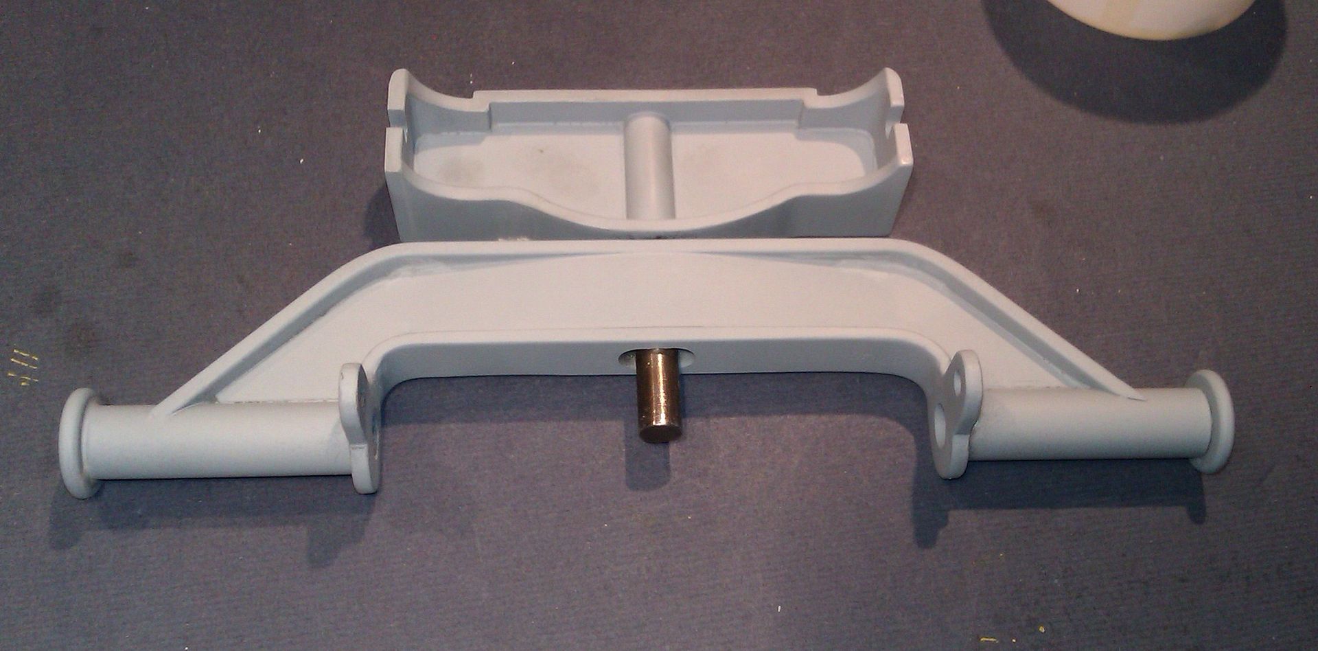
The next bit on my Galloway cart is the front axle, this is what I'm aiming for
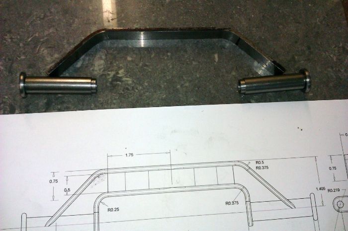
Started cutting and bending a few bits, the full size drawing comes in handy to lay the bent parts on to check the shape
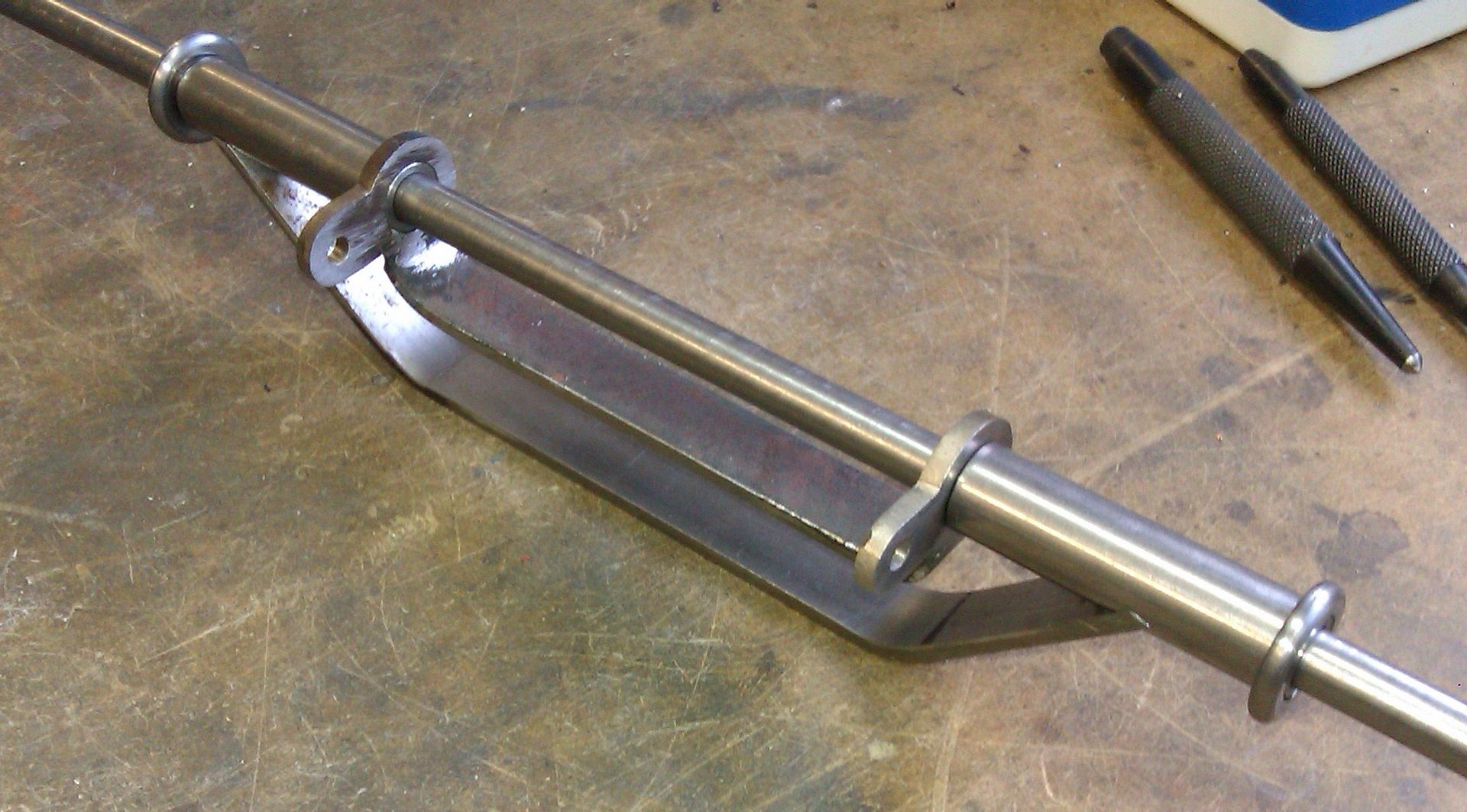
Comming on with a dummy axle
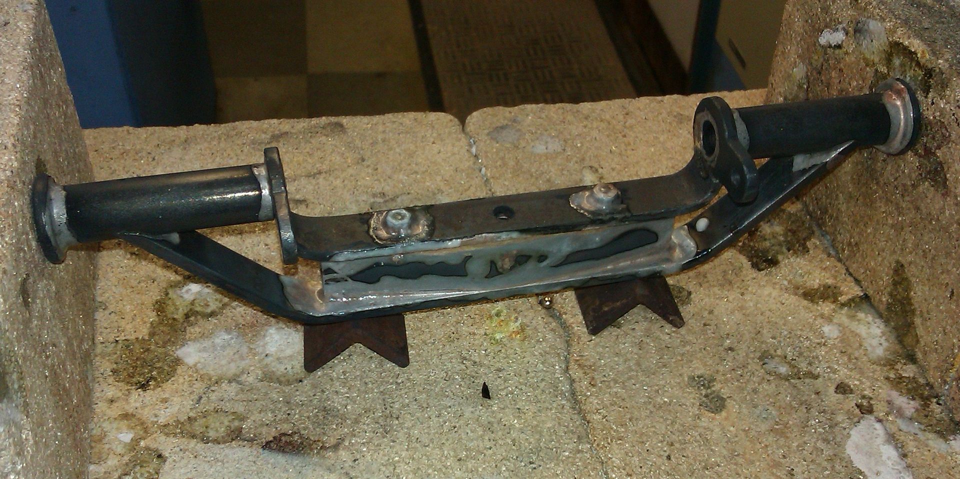
Add a bit in the middle for good measure shaped from some 5/8" sq hot rolled then silver solder together
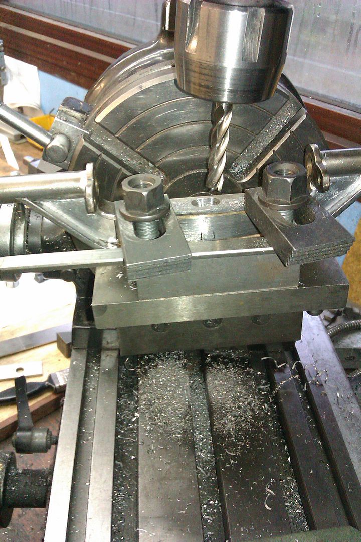
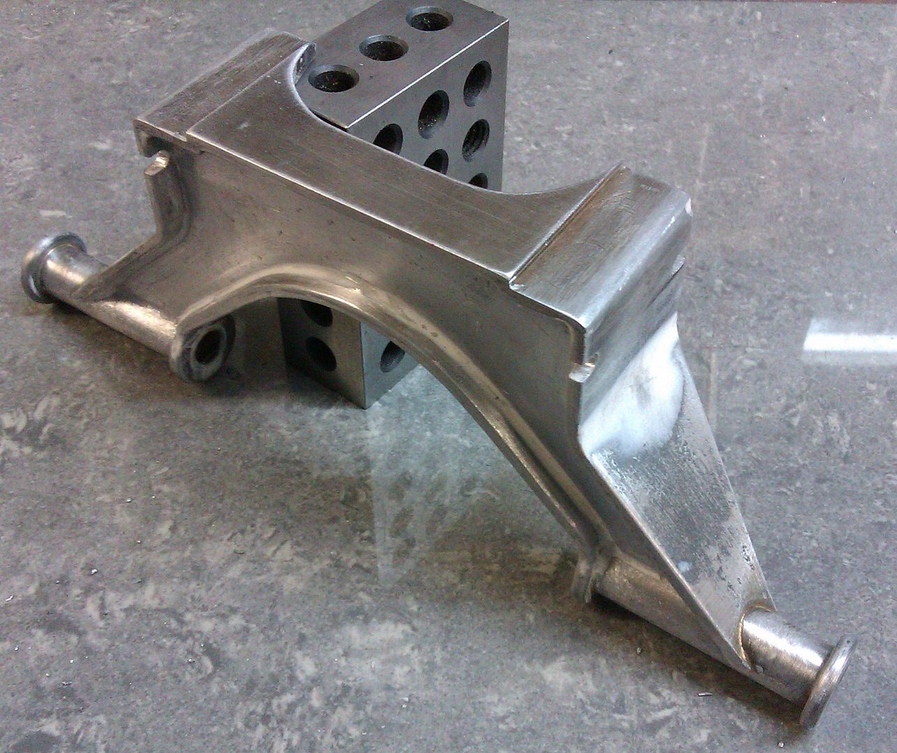
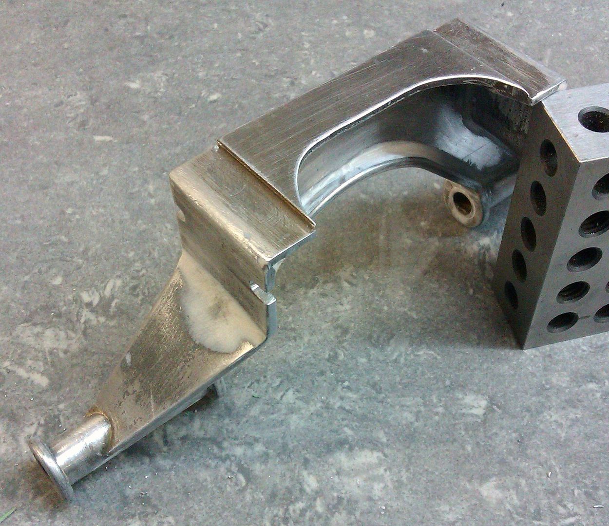
After a pickle the tricky bit of making a tapered hole that is round at the top and oval at the bottom so the axle can articulate but still rotate without any slop. The top was set to the rotary tables centre line on an angle plate and the table rotated 8deg each way.
Just a bit of filleting to add to the internal corners and it will be finished
went to "work" and spent day being paid to sit there reading latest MEW- cant be bad! Better than reading it @ home and not being paid. I am after all, only working part-time in my deferred retirement for a short while for a bit of extra dosh. Only need to answer phone about twice a day and a few other little jobs. Last week helped put up office Xmas decorations, assisted by a muslim lad! Dont believe all you read in newspapers about them being offended by Christainity. Probably only a few fanatics give them all a bad name.
Geoff: – Make the jig, it is worth an hour's fiddling. I also made a jig to grind the lap angle accurately.
John: – The blades were purchased over 12 months ago (never broke the original until yesterday, and it did mighty cuts while it lasted). Also the supplier is in Melbourne, 3 hours by car, maybe a week by post if I'm lucky.
Ian: – You seem to be a pretty resourceful bloke (from your posts), how come you do not attempt to repair them yourself?
Given all that, have decided to purchase a roll of bi-metallic blade material, cut it to length and investigate the old '12V car battery spot welding technique'. Any ideas?
Danny M, May or may not be useful but the DoAll band saws had a butt welding device built in and its worth noting there was a button to press after the weld to anneal the weld. You set the blade in the clamps, pressed a lever to move them together creating the weld then release one of the clamps allowing it to return to its rest position, re-tighten and then anneal.
There was also a gadget to grind the flash off and a gauge for thickness.
John: – The blades were purchased over 12 months ago (never broke the original until yesterday, and it did mighty cuts while it lasted). Also the supplier is in Melbourne, 3 hours by car, maybe a week by post if I'm lucky.
* Danny M *
Danny,
Guessing from your location that it would be a problem the reply was a bit tongue in cheek.
Went to town today, and was most disappointed, my supplier of bandsaw blades no longer welds them, although they can send them, to Auckland (head office), not sure of the cost of that, but a bi-metal blade costs about $NZ 45. I did get a name of an engineering firm who join blades, but not sure if they can do the 1/2" wide ones, other wise I'll have to look out my brazing jig, I might have to do better than by eye with the chamfer. Ian S C
To grind the chamfer I made a little jig from a scrap of crappy aluminium. Had to cut the block by hand as all the blades were broken or too small. I made the chamfer angle 20º as it looked about right. Milled a 13mm wide x 0.5mm deep slot to suit 1/2" x 0.025'" blades. Drilled & tapped some 3mm holes near the edge of the slot so that the blade could be clamped in the slot. The pointy end of the jig is squared off as my fence has a stop- screw on the end.
In use, clamp the broken blade in the jig with enough projecting to just kiss the side of the wheel. Set the fence on your table to about 1º so that as the table is moved in towards the wheel a little more of the blade is ground away.
When you do the other end, don't forget to flip the blade or the bevels will not coincide . Also, when actually doing the grinding, don't forget that the other end of the blade is dancing around somewhere behind your back.
1. The grinding table is from Harold Hall's Workshop Practice book, Tool & Cutter Grinding.
2. The blades were already repaired when i saw your message.
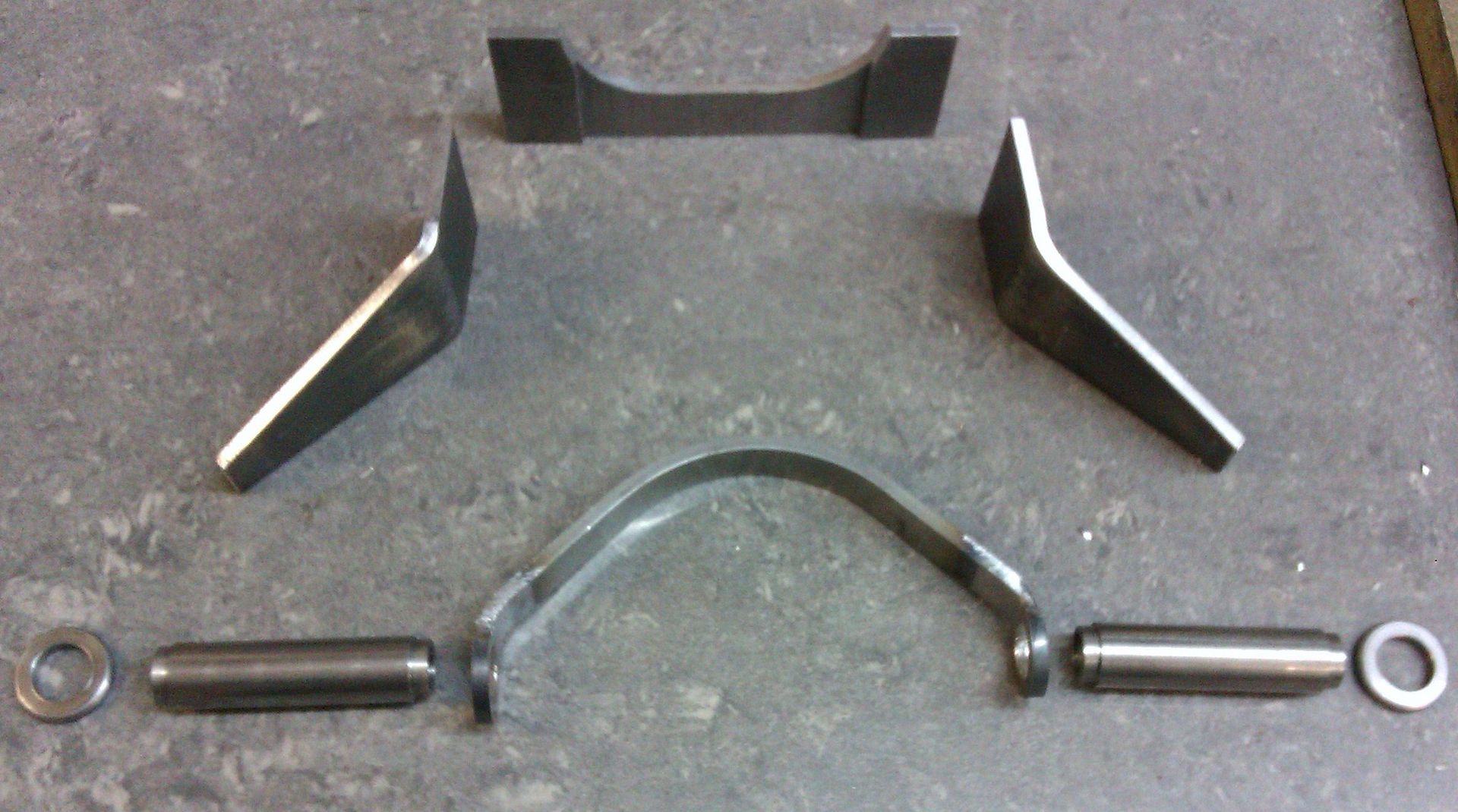
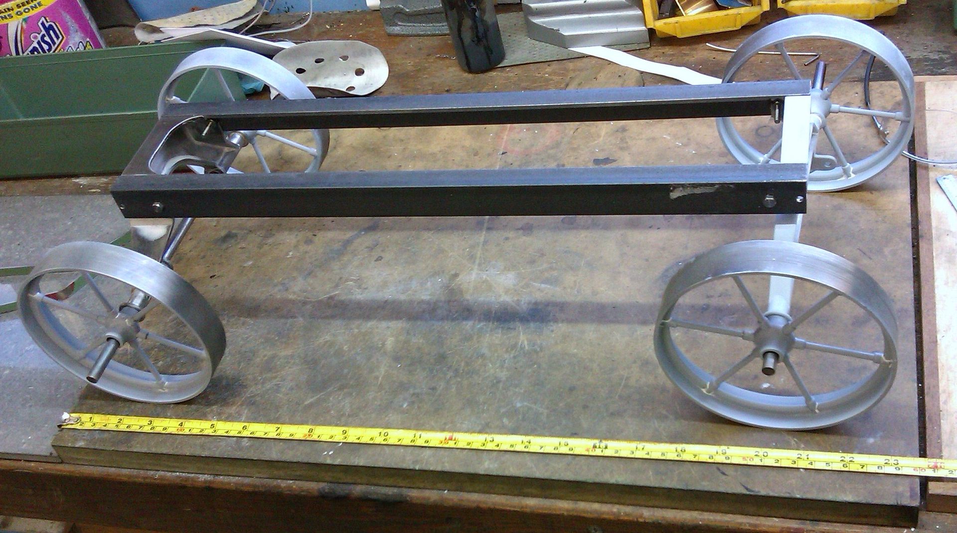
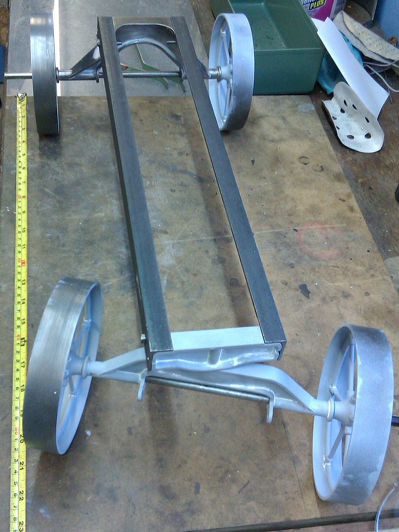
I've spent the weekend making the back axlefor my Galloway cart. Here are most of the pieces, the "V" shaped flange is actually two washer shaped parts welded to the bent strip.
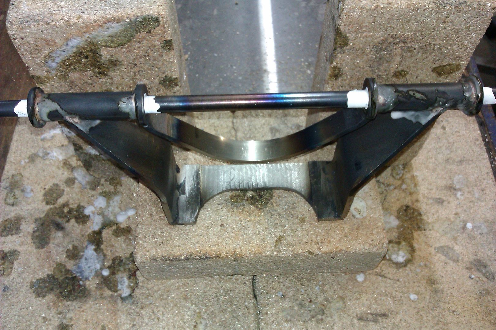
I than slipped a bit of rod through to keep things in line while it was silver soldered, note the white Tipex to stop the rod getting soldered in place
After an hour in the pickle the central web was soft soldered in place and the whole thing given a good fettle and fill.
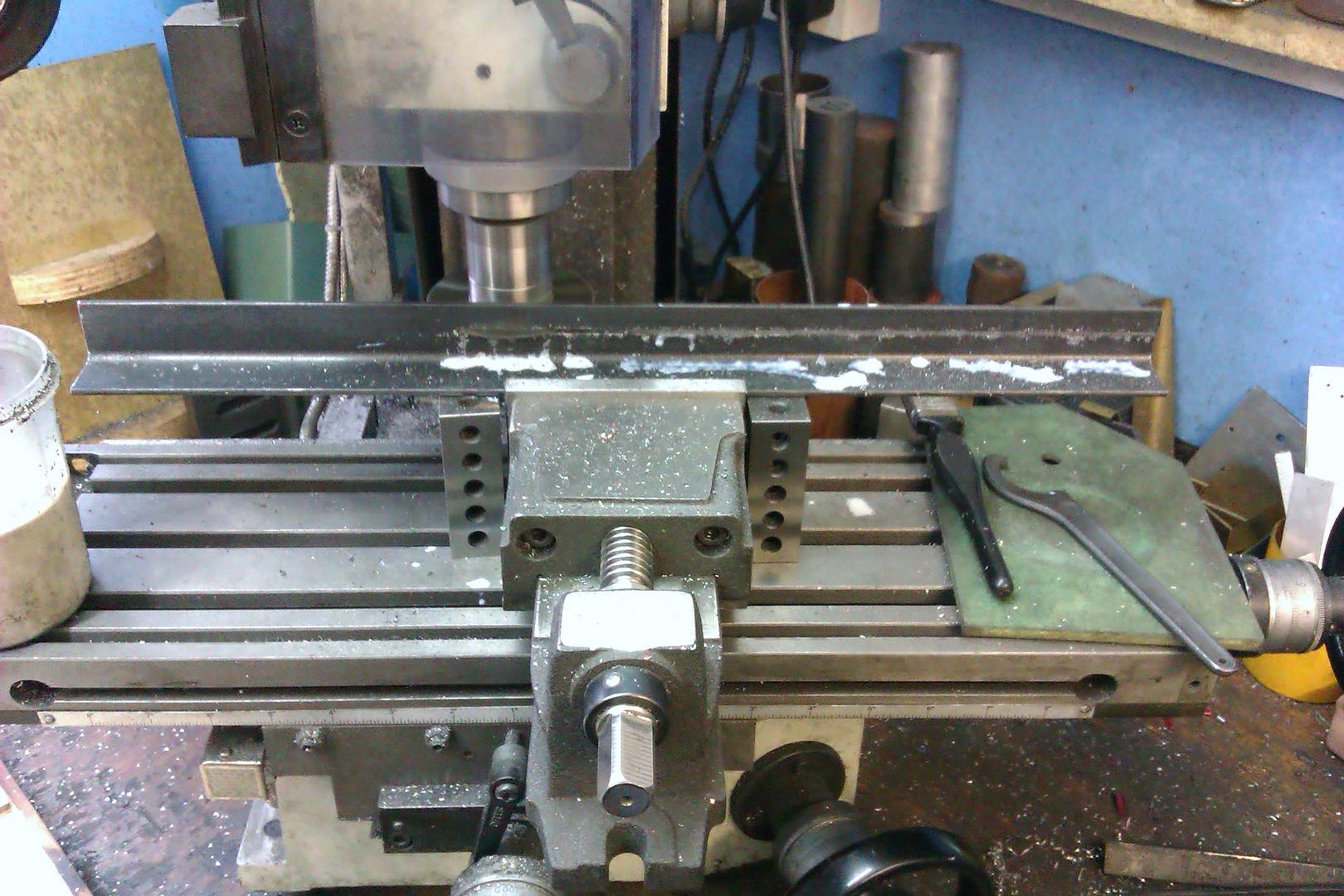
With that done I cut down two 18.5" lengths of 30x30x3 steel angle to give 1/3rd scale 2"x3" angle
Don't panic I did it in three stages moving the work approx 6" at a time. Then a few holes followed by a trial assembly.
Thats all for now.
Anyone else been doing any thing in their workshops? or are you all sitting in the armchair keeping warm
Sat in the arm chair now keeping warm. Started my Stuard V10 which I bought when I visited the Bristol Show last August. I finished the boxbed this afternoon. It's going to be a new pick up, put down project that will give me some workshop whilst the dining room gets its new hard wood floor, French doors and log burner.
Spent a few happy hours fettling a woodworking lathe, chucks and tooling that I've had for a while. I bought this from a friend some years ago and have decided that it will be far more use to my Son in Law than it is to me. What's more it will probably be a bit more interesting ( although maybe not more useful!) than the superb knitting my wife has done for his Xmas present!
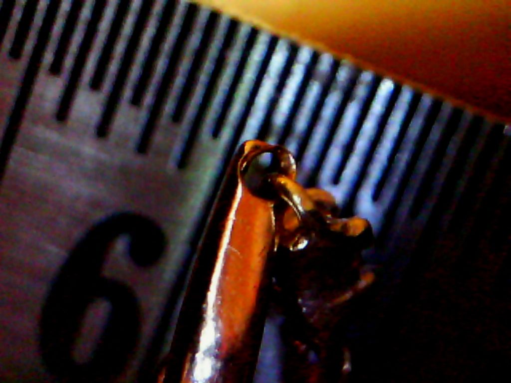
One of the tiny links had literally worn through, so I added a little bit of gold by soldering some on. I had to use hallmark quality gold solder (its like silver solder, but made with gold instead of silver). I had to use a tiny, intensely hot, flame to melt it without melting the other link.
The rule in the photo is marked with 0.5mm divisions..
Whoo hoo, new 3D printer arrived this morning! Took a couple of hours from opening the box to making the first part; the instructions never quite match reality. Here are the bits straight out of the box:
And here it is set up and running:
Note the traction engine bits on the left, and work stuff (MMO gas sensors) on the right, plus the obligatory cup of tea. Here it's printing the first part:
And the part itself:
The system can only print from an SD card, and my computer is so old it hasn't got an SD card slot. So first thing tomorrow it's down to the local PC shop to buy a USB to multimedia adaptor.
There is a USB-B connector on the back of the unit, but the manufacturer's support site clearly states that USB is for software upgrades only. Just for the hell of it I did connect a PC and sure enough it couldn't see it.
You might need software eg repetier( will need that later anyway..) and the “com port” usb driver….normaly comes as part of audrino development pack.. assuming audrino based ( ultimaker claim open source so look it up )
Bought a USB to multi-media adaptor this morning, and then made a few more parts:
The towers were downloaded from the internet, but the box on the right was drawn in Alibre, saved as a STL file, put through the slicing software and then printed. That proves the complete design chain; all I need to do now is work out what it is I need to design! Overall I'm pretty darn pleased with my printer.