I watched F1 qualifying and then did a few hours in the local museum BUT I then came home and watched the FA Cup Final and cheered on Wigan. Not bad for a geriatric Scotsman but I always support the wee team. I'll try to get back into the workshop tomorrow after F1.
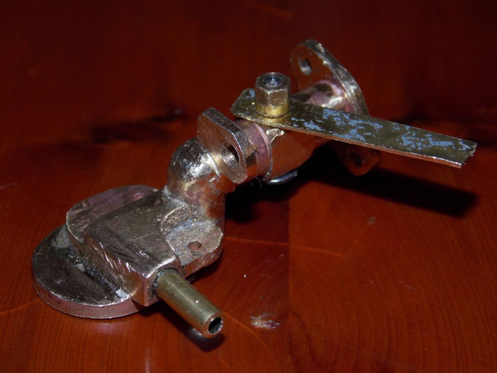
I fabricated the upper part of my carburettor, it will be a simplified version of the original with just float chamber, a single jet with needle control, a simple throttle and butterfly choke. No idle jets etc.
I figure that if the float doesn't work, I will just have to adjust the position of the fuel tank,
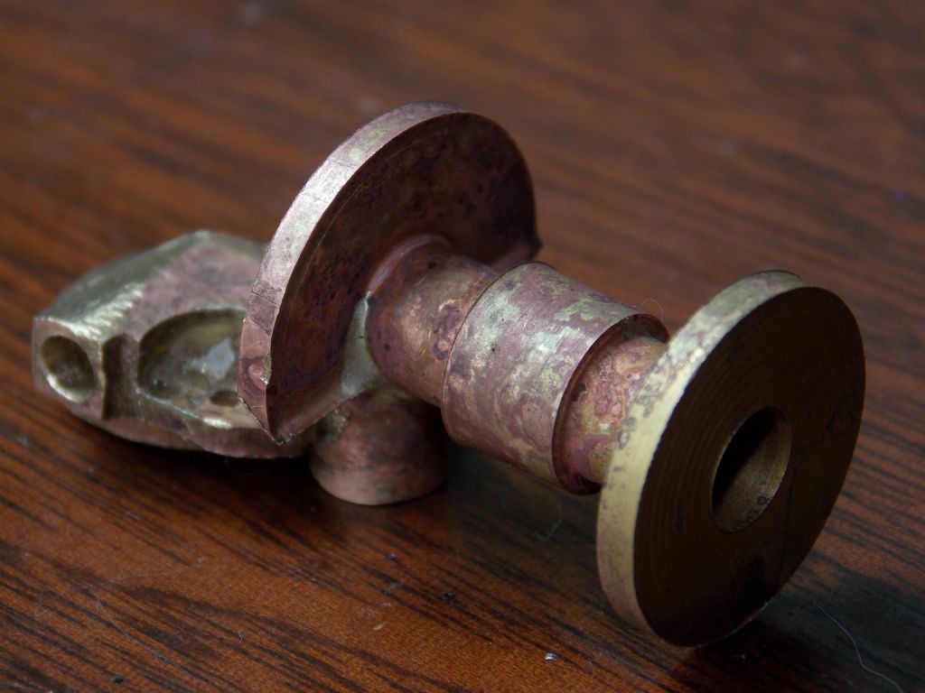
The part in question is in four bits that took some creative thinking to jig together without any screws. Used a toolmaker's clamp to support the top tube by its mounting flange, lined up the rest of the bits and leant part of a broken ball race on top to hold it all steady.
That was a great idea, as when it cooled down the ball race was firmly soldered to the lid of the float chamber and the 'bit that goes on top of it'.
Fortunately, I was pretty generous with the heat, and teh ball race was fully annealed and I was able to saw it off – VERY carefully.
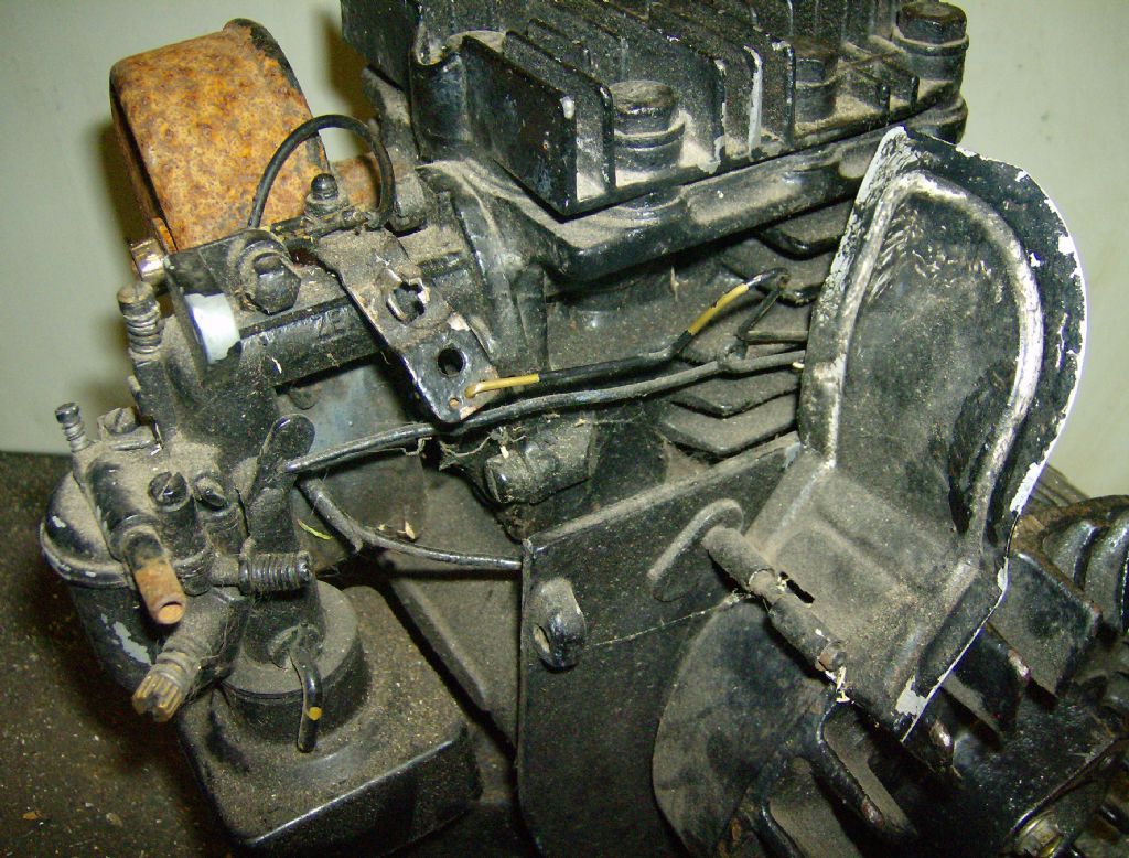
Now soaking in descaler overnight – I'm beginning to think it may be possible to do this. Pic below shows the original carb at left before I cleaned the black paint off and unblocked the holes.
Put up an extra eighteen linear foot of 5 shelf racking in Gerts domain to try to sort out her Ebay goodies.
nothing interesting, all smellies, candles, wind chimes and stinky stuff.
The type of gear you go can your whole life not owing and not miss it, but it keeps her happy.
To stay withing workshop topic limits finished up with 3 big boxes of damamged candles and old stock to melt down and re-mix into engineering plastic suitable for training pieces on the CNC's.
Spent the last 2 days trying to fix my computer. Looked like a HD failed but in fact appears to be the SATA controler that broke. In between watching restore processes on the computer I managed to make a little more progress on the ball turning tools.
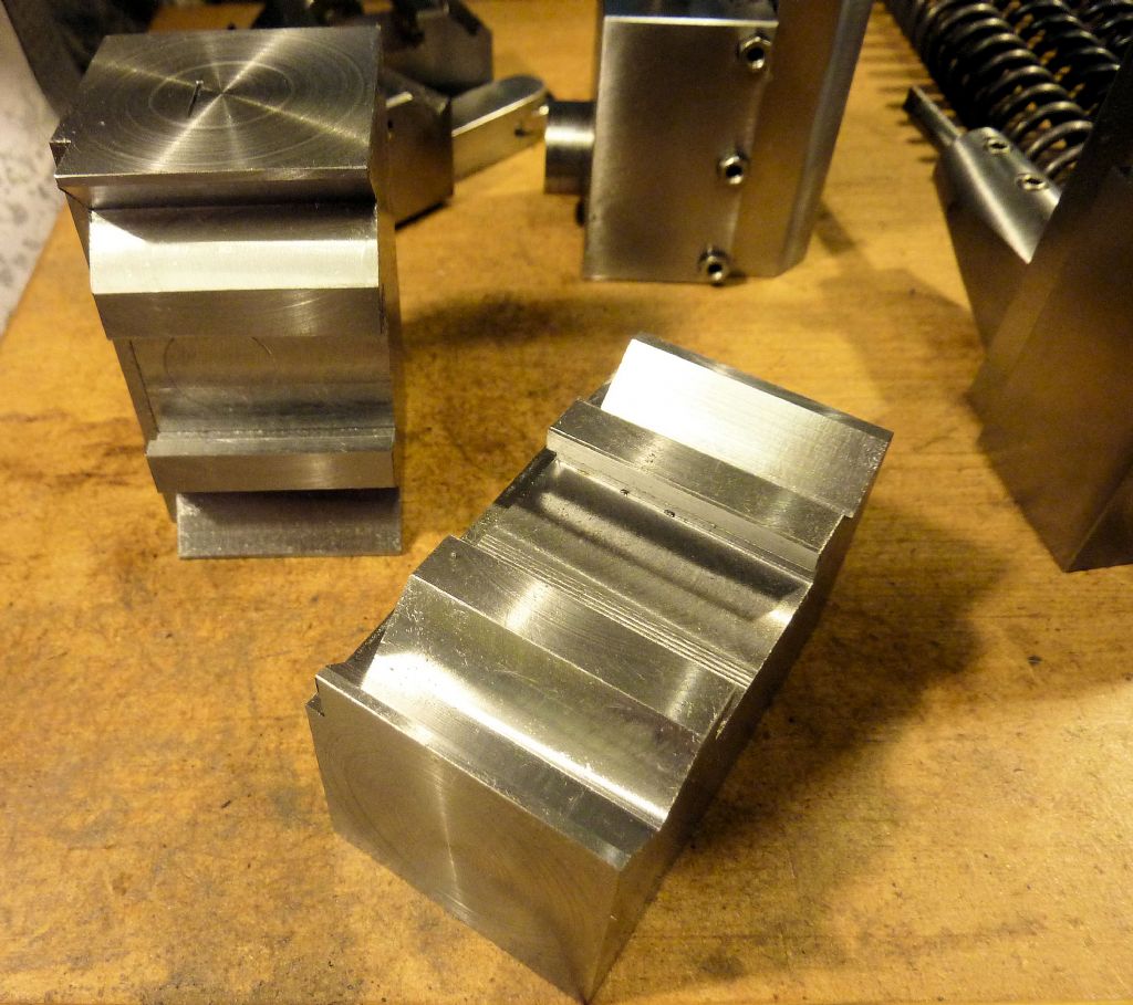
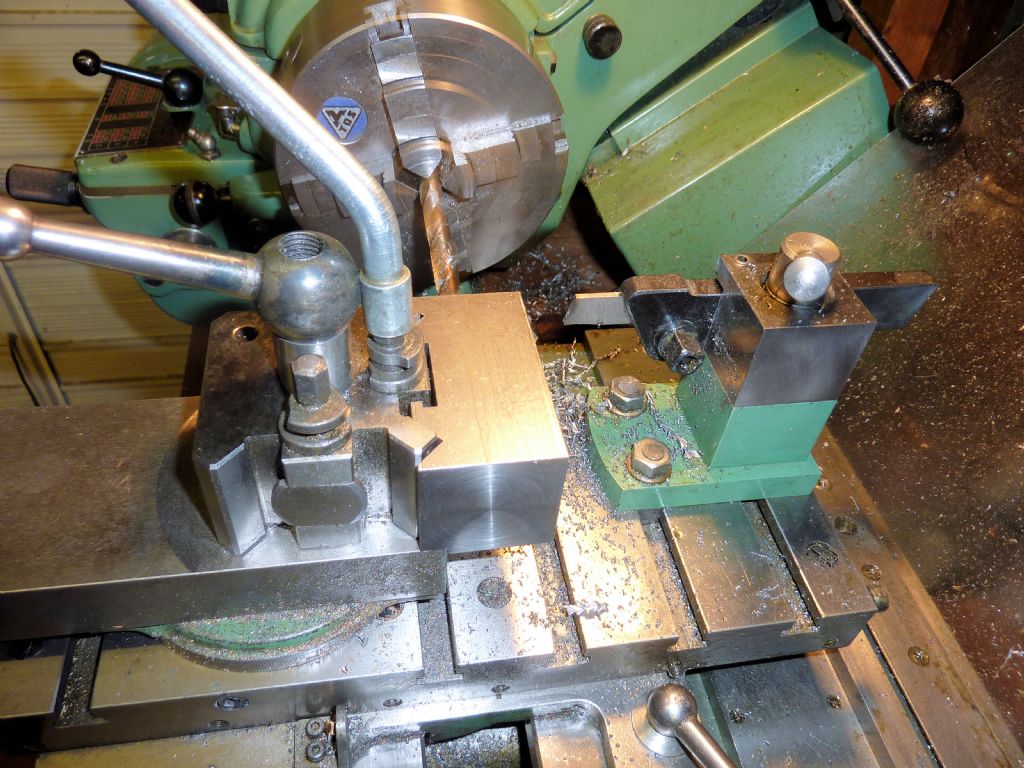
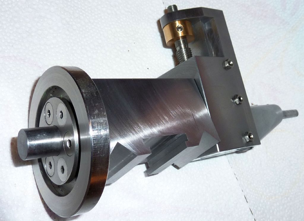
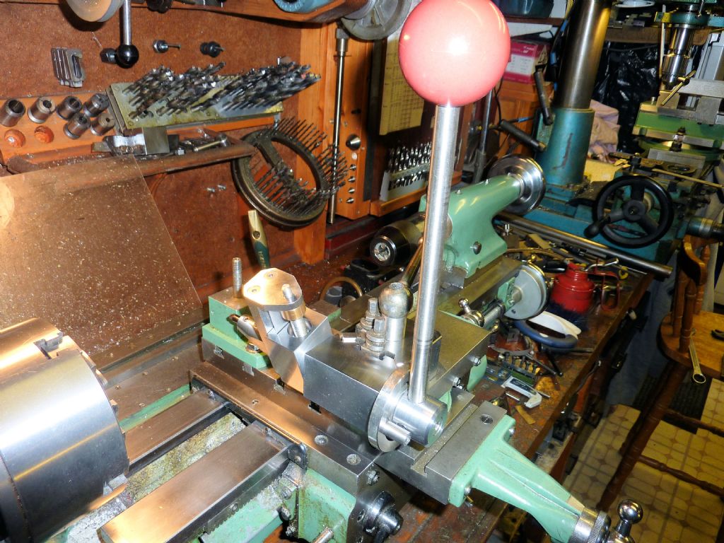
Milled a couple of blocks to fit my Dickson-type quick change toolpost
These were then drilled and reamed 1/2" to accpet the pivot shaft.
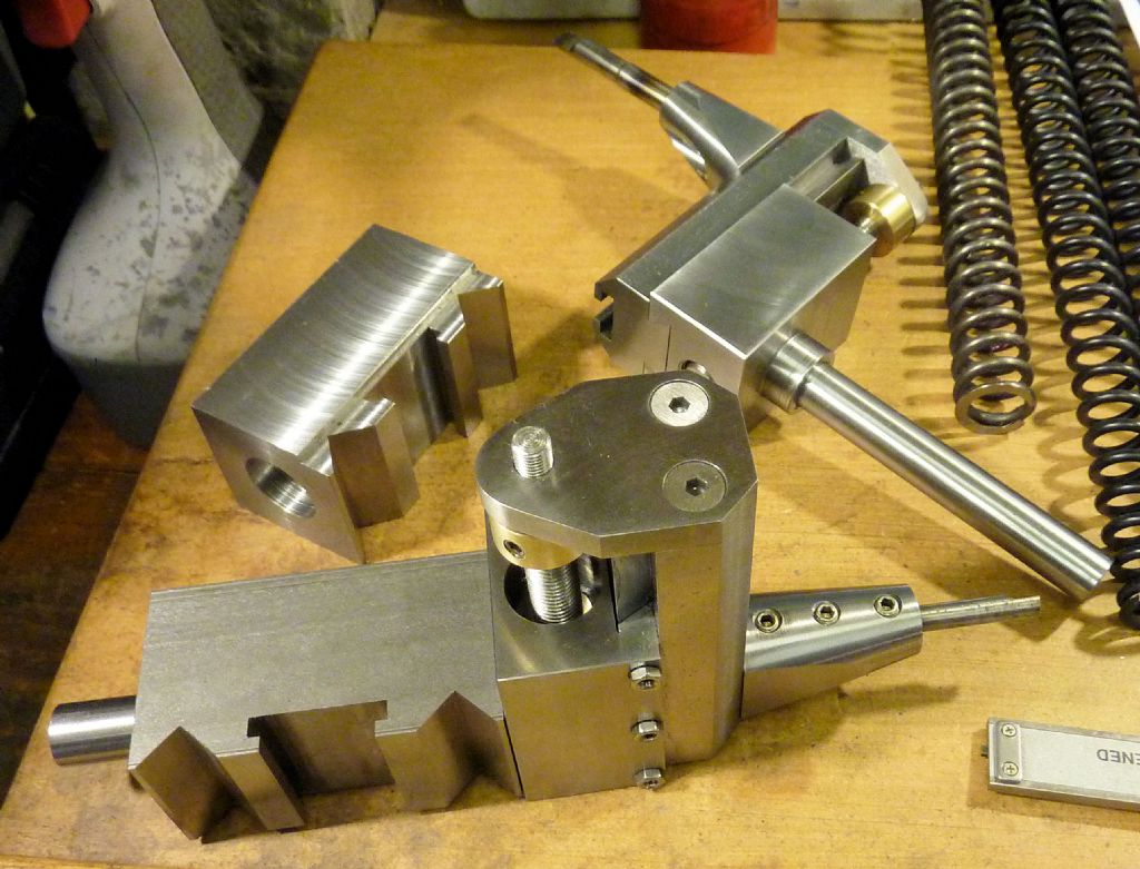
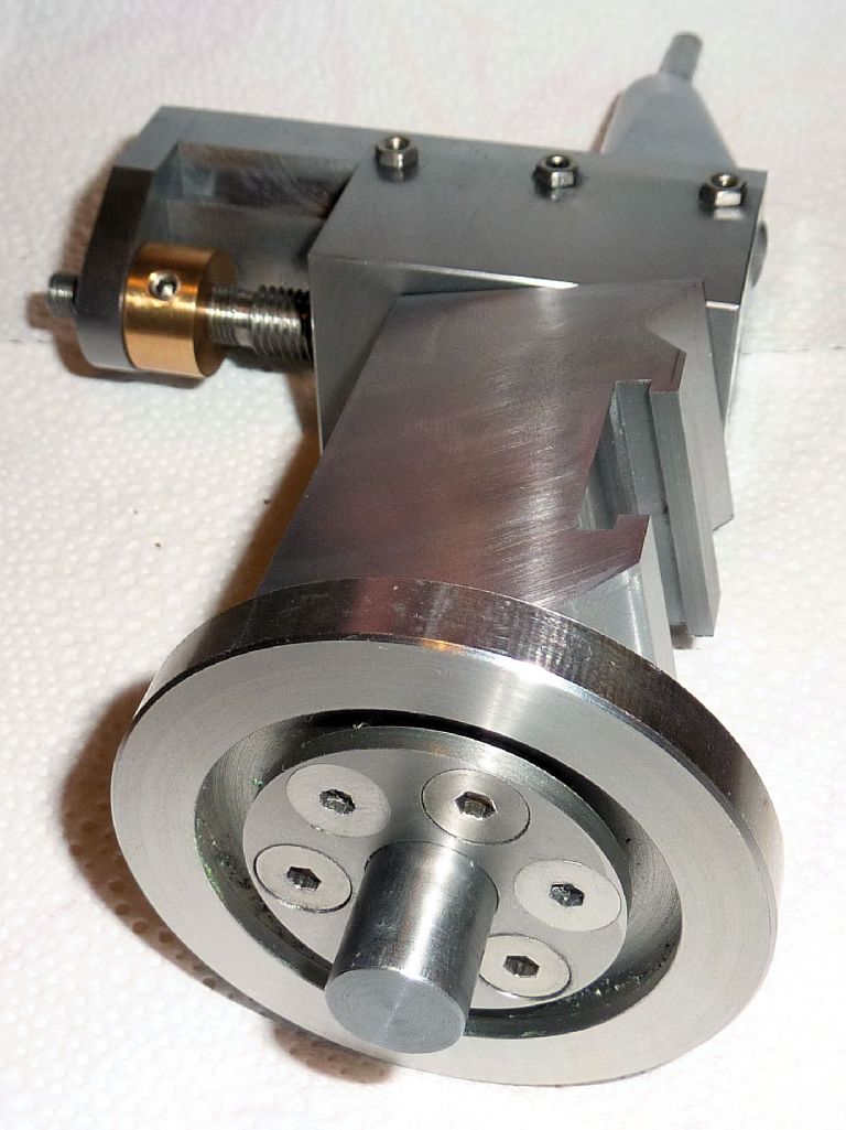
The ball turning head fits in these blocks, something like this:
Took me a while due to working away from home commitments but I got there in the end. Many thanks to Harold Hall. I have learn't so much whilst making the rest which will be a big help to me in the future hopefully. No great achievement compared to some of the work shown on this site but we all have to start somewhere I suppose.
I havent done the graduations to the dials yet. Thats another chapter.
Oh but I did finally work out how to post a picture into a posting so happy days all round ! ! !
Out of interest how long did it take you to make the tool holder?
Bri
Hmm. Don't know really. I've been at it nearly 2 weeks now but I haven't been in the workshop every day. Maybe 20 hours so far.
.oOo.
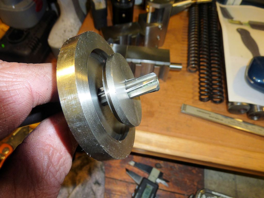
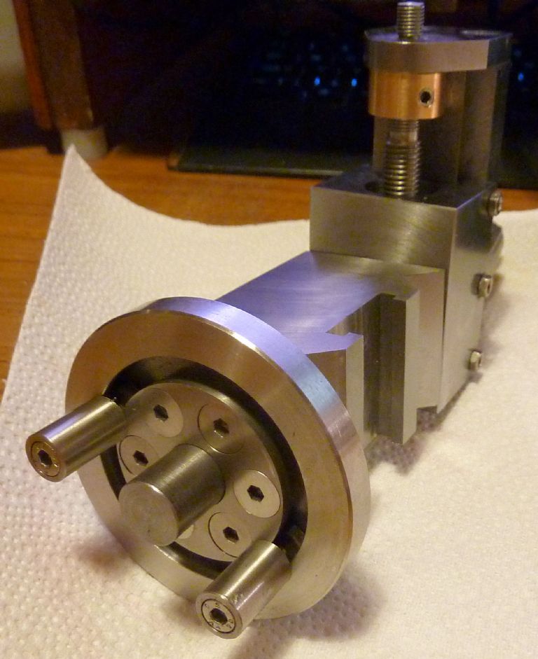
I made part of the adjustable limit stop, this fits on the end of the block and allows you to set where the cut starts and ends. Several ways of doing this occured to me and I fancied a circular T-slot (so it's a C-slot?). Anyway, I was going to use a t-slot cutter on a circular blank clamped to the rotating table but experience cutting the stainless steel (formerly residing in the scrap bin) in the lathe suggested this would present a problem. The metal is very tough to cut. So change of plan – I made the thing in two parts held together by screws.
I need to make the captive nuts and the two stop pins yet, but when assembled the pins can be positioned at any point around the slot.
Continued with the ball turning tool, not sure how it was going to turn out so concentrated on completing just one of the pair.
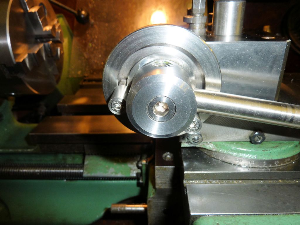
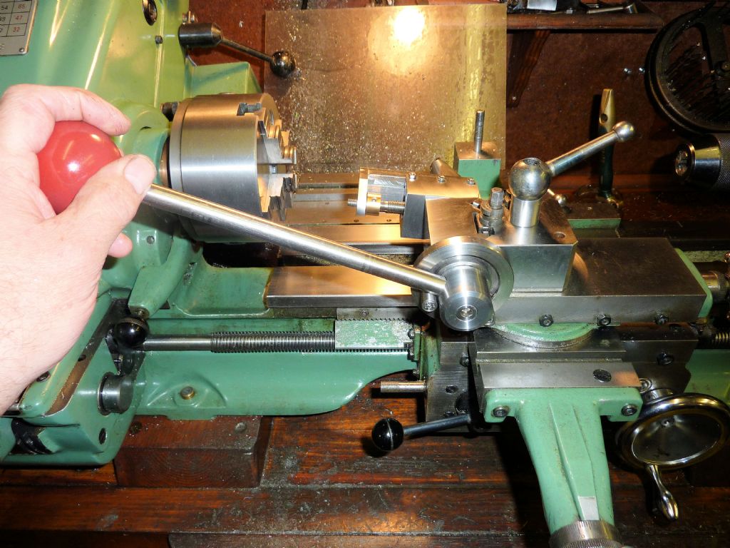
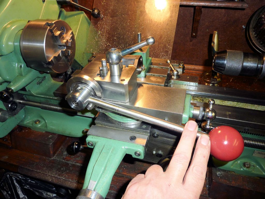
The limit stop works fine, easy to set and effective:
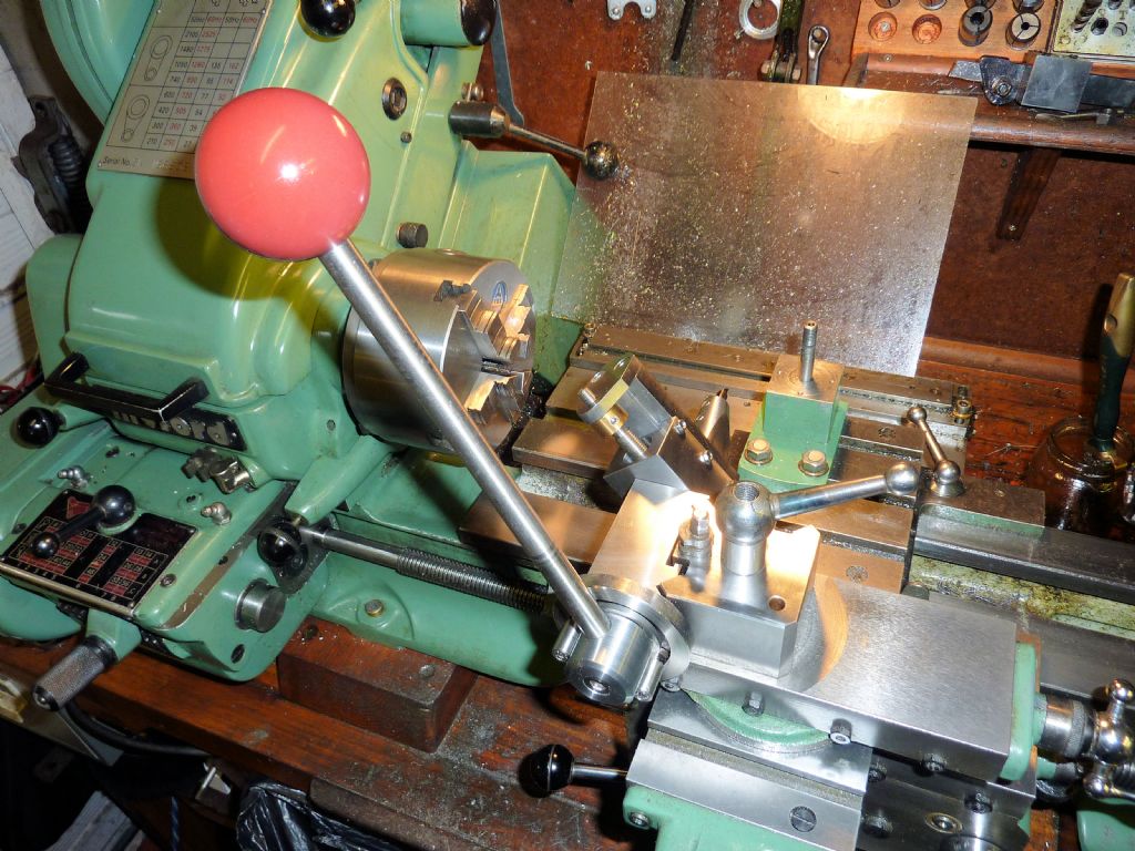
I knew this 30 year-old snooker ball would come in handy for something one day LOL!
Not the easiest thing to hold for machining though… Anyway, I just need to make the depth of cut knob, then install an oil nipple in the main block for the pivot shaft, and the job's complete. Happy days
Fitted a slotting head to the WM40 Bligeport, a Bligeport is a Chinese copy of the Bridgeport and in the case of the WM40 it's far bigger, beefier and heavier.
Usual problem is that one job leads on to 5 more.
The widen the ears to fit the bigger WM40 ram, 10mm has to be removed, 6mm off one side and 4mm from the other. An extended R8 arbor is needed to reach down 5".
Dummy run to test fit of the bracket and the spacers etc.
Test assembly.
Slotter lifted up, dropped on the bed and clamped in the vise. From here it's just a matter of using the 3 power feeds to slide the slotter onto the ram and bolt up.
Didn't get a picture of the sight gauge before but it was cracked, dirty and loads of crud behind it. No chance of getting a new sight level so broke the clear lens up and prized the sight out.
Cleaned it all up and with a pair of needle nosed pliers the roll over return that held the lens in was open up.
Cut a new lens on the laser cutter with reversed engraving on the rear, filled with red paint then the excess was wiped off. Lens pushed back into place and the lip peened back over.
Just got to do a couple of jobs and then it's being removed again and sent away for painting to match the rest of the machine.
Cleaned it all up and with a pair of needle nosed pliers the roll over return that held the lens in was open up.
Cut a new lens on the laser cutter with reversed engraving on the rear, filled with red paint then the excess was wiped off. Lens pushed back into place and the lip peened back over.
Hi Paul,
I have not seen the PC interface in your link before. It looks like an updated version of the YADRO DRO. I built a Yadro dro a few years ago. It worked well using an old laptop running DOS. I now use the digital caliper type scales with DRO350's (Shumatech) I have done some work writing code to read various versions of these scales using PIC micro's. There is a guy working on using an Android tablet PC with an Atmel micro to interface with the scales. The Atmel communicates with the Android device via a wireless serial bluetooth interface. I have tried his Android software and sent data to it from a bluetooth interface on a PC. It worked without a problem. Here is a LINK to this site. On another subject was it you at the Harrogate exhibition with your flash steam hydroplane ?
Hi Les thanks for the other links I am the guilty one at Harrogate with the hydro.
Just been given a job today for my Natural History friend he has found an unusual fungi on a juniper as he has no computer so I am sending pictures to Defra and Yorkshire Wildlife Trust.
With so many foreign diseases etc. decimating our natural species we don’t know what’s round the corner.
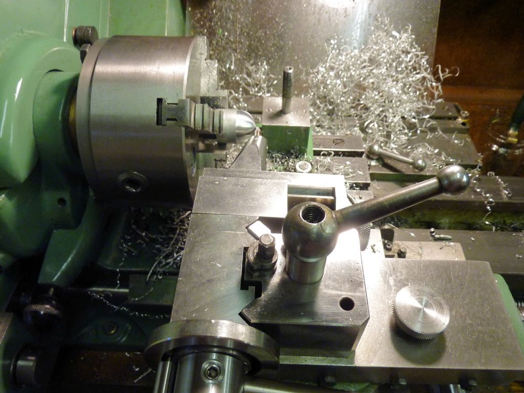
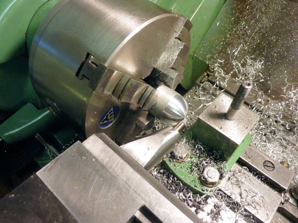
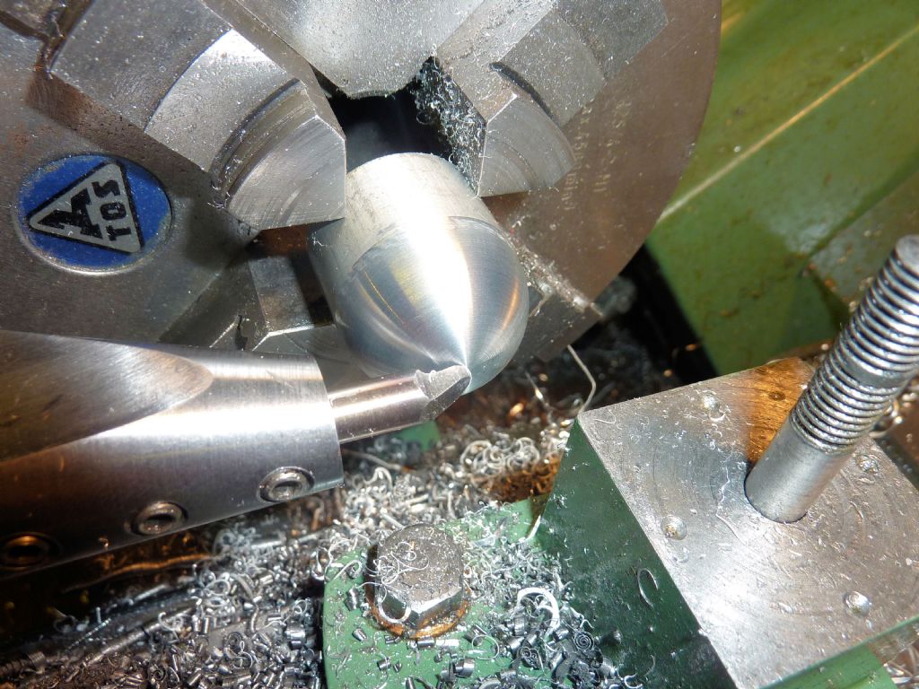
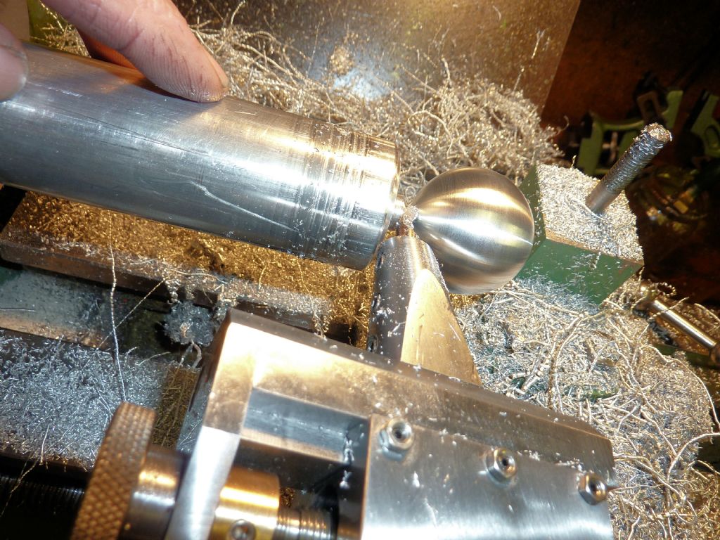
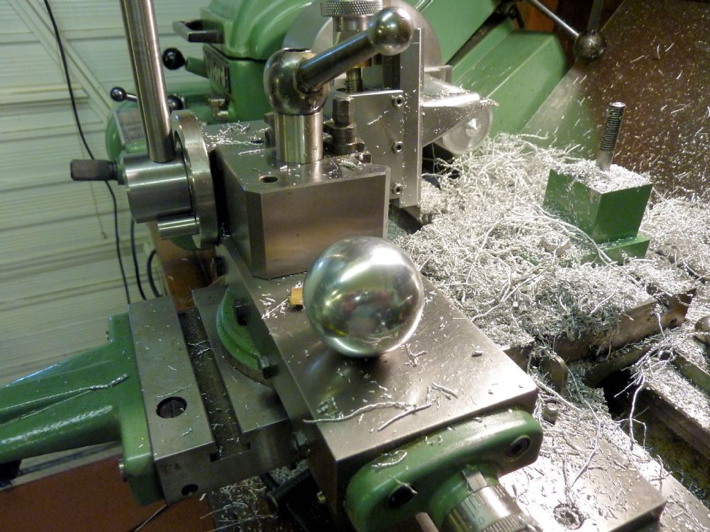
Sorry, a couple more pics… just to prove the tool can make complete balls rather than just radiusing the end of a rod. Making a 1.5" alloy ball produces a fair amount of swarf!
Just the last little bit – I have to hang on to it as the ball is cut off (I still dropped it later…)
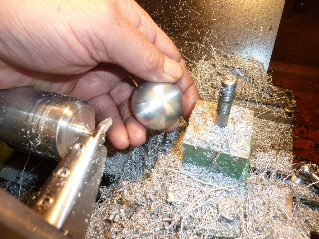
And there we are, no avoiding a small pip but it can be smoothed off with emery paper and a polish. There was an excellent finish until I decided to give it a final skim when it chattered a bit (there was hardly anything holding it on the stub so it was a bit stupid to try…)
Bit of a polish as stated and a perfect ball is the result.
Amazing when you look on the web how many different designs there are for spherical turning tools.
You've got my botanical juices flowing going now! Post a pic of this strange fungus.
I had you down as a Warwickshire lad, but my GFungus Flora of Warwickshire doesn't record any fungi on Juniper (to be honest I don't think there IS and wild juniper in Warwickshire).
Hi Chris H.
What's the point of making a lovely ball turning tool, and then using a snooker ball on the end of the handle…?