Pondered Vee-blocks, with assorted key-ways, cross-drilling and such like looming.
I have two pairs of large-ish Vee-blocks of webbed form with holes through the webs, inviting spot-facing those and making matched tubular spacers to hold them together with studding.
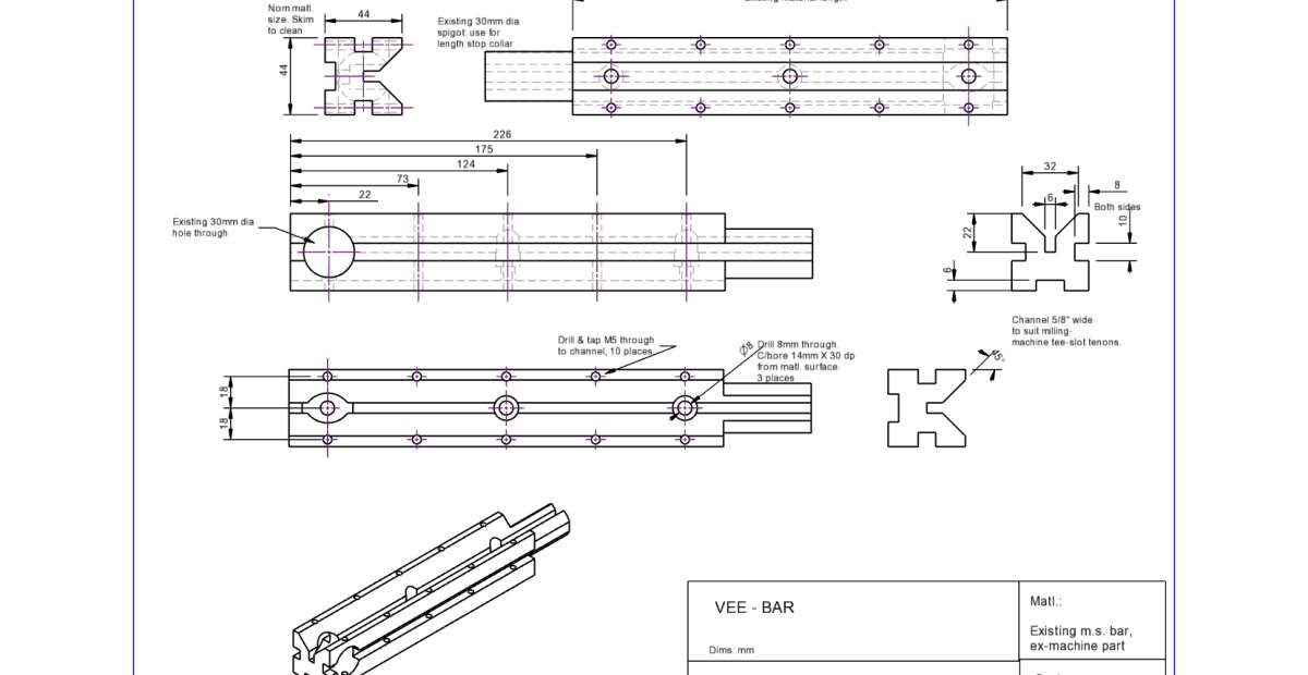
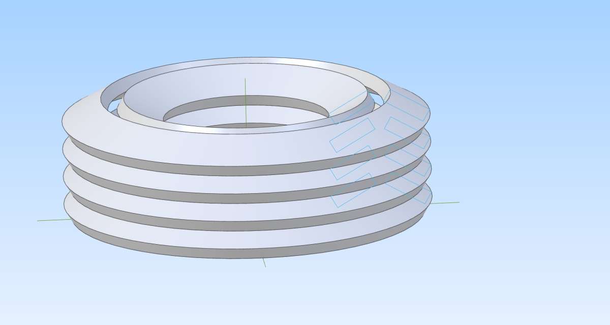
Then though, why not a long Vee-Bar channelled to fit the tenons I made to locate the dividing-head and its tailstock along a Tee-slot on the milling-machine.
I’ve even a length of 44m square steel bar ideal for the purpose… and even succeeded in producing a drawing for it.
Though of course for anything more than about 5/8″ diameter is just as easy to use the Tee-slot as a “Vee-block” of sorts anyway.
Still, it was a useful drawing exercise (about 3 hours of brain-fading), it’s designed with versatility and rapid setting in mind and it can also be used as a long fence / angle-plate.
I have no idea what the material was, but I opted to keep the hole and the spigot, which is 30mm diameter. I’ve no idea what I might use the hole for but the spigot could hold a simple end-stop collar. The idea is to screw this to the table by 3 M8 T-nuts and cap-screws. The 5 pairs of M5 tapped holes are for simple bridge-clamps.
“Drilling” those M5 holes – shown just as 5mm holes – proved odd. I wanted them to go just through into the side channels but Alibre said “Shan’t” – in computerese – though let me put them right through. So that’s what I did, then twigged that might be useful for machining the thing – tap the lower ends of the holes as well, and then they can be used with suitable bars engaging the flanges of the Vee-blocks to hold the workpiece from below, allowing profiling right through. I wonder if the problem was that the holes are sectioned by the channel – I’d drawn the entire profile first – but it didn’t stop them extruding right through.
So I’d also made the mistake of adding the counterbored M8 holes with the “Y” – channel all done, and realised that might be as problematical digitally as in swarf-making. So, not sure if this would work, I gave the bar a temporary cover 2mm thick, generated the holes and counterbores from that, then stripped off the cover. It worked!
Making it in reality needs all of the holes first, then the profile cutting.
Size? The dimensions, all mm except the 5/8″ wide mortice, might not be readable here but the basic bar is just under 250mm long and 44mm square.

Dalboy.


