What did you do Today 2024

Advert

What did you do Today 2024

Home Forums The Tea Room What did you do Today 2024

Viewing 25 posts - 26 through 50 (of 519 total)
  • Author
    Posts
  • #708513
    Craig Brown
    Participant
      @craigbrown60096

      20240119_144107

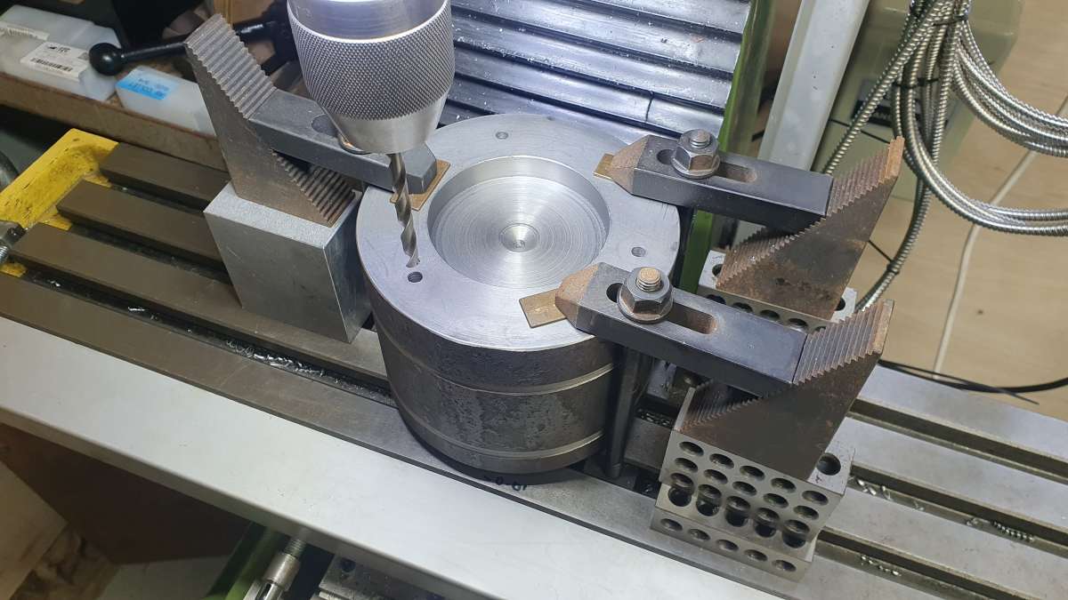
      Set the riser up on the mill to drill the holes. Most of the time was spent trying to get my head around the PCD function on the DRO. Once I had that sussed out I set to drilling. My plan is to through drill the entire block. I have drilled 1/4″ about 1.5″ deep and plan to follow that with a 12mm slot drill to correct any wander then use that to guide a 12mm drill to complete the hole. Hopefully this will ensure the holes remain straight.

      Advert
      #708523
      John Hinkley
      Participant
        @johnhinkley26699

        Hi, Craig,

        Are you planning to make an extra long Z-axis screw to accommodate the longer travel?  I’m assuming that’s my old Warco VMC in the picture.  The DRO Z-axis scale will need to be replaced with a longer one, too, I guess?

        John


        #708529
        Craig Brown
        Participant
          @craigbrown60096

          Hi John

          Indeed it is your old mill. I had wondered if I would run out of Z axis travel but before I started the job I raised the table as far as I dared without winding the screw out of the nut (ill advised apparently) and the table came up surprisingly high, pretty close to the spindle nose infact. So considering that 95% of the time a vice will be on the table, as well as a collet holder in the spindle, I think I’m unlikely to run into trouble. Not forgetting the 75mm or so of quill travel too. The DRO scale is also fine.

          Cheers, Craig

          #708536
          John Hinkley
          Participant
            @johnhinkley26699

            Craig,

            That’s good to know.  If you do decide a longer screw is required, John Mills (Doubleboost on YouTube) did a video or two on the subject for his Chester 626 mill.

            John


            #708546
            Mark Rand
            Participant
              @markrand96270

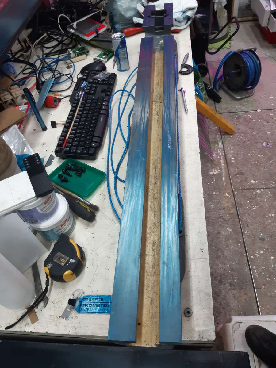
              After a day heat soaking the surface table and the ML7 bed I blued the table up and checked the lathe bed. After scraping off the raised ledges around a few long scratches from swarf caught in the carriage wipers and dents from things being dropped on the bed, I got a markup that shows that the bed is still pretty flat:-

              20240119_153121

              The blue on the surface table was freshly applied, so heavier than one would work down to when progressing through a series of scraping passes. Even so, the coverage is better than any of the machines that I’ve rebuilt so far. careful measurements of the thickness of the ways showed that the wear is actually 0.15 thou. This compares with the 0.12 thou that I measured when lapping and calibrating the surface table. Scraping the top of the bed would give little benefit.

              Careful measurement of the vertical sheers shows 0.8 thou of wear between the sheers on the front part of the bed. The sheers on the rear part of the bed show 1.5 thou of end-to-end variation. Which is confusing since the tailstock it the only thing that uses the rear, inside, vertical sheer. These measurements were repeatable.

              I think that the next step is to check and, if necessary, re-scrape my 48″ straight edge. Then use it as a reference to re-scrape the rear vertical sheer and use that as the standard to re-align the other three vertical sheers.


              #708556
              Speedy Builder5
              Participant
                @speedybuilder5

                Good to see a nice tidy bench !!  – like wot I got too.

                #708761
                Mark Rand
                Participant
                  @markrand96270
                  On Speedy Builder5 Said:

                  Good to see a nice tidy bench !!  – like wot I got too.

                  The surface table’s nice and clear though 😀

                  #709855
                  Colin Heseltine
                  Participant
                    @colinheseltine48622

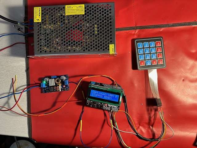
                    Last few days spent looking at Arduino Indexer.  I made the Steve Ward one several years but had also purchased the Arduino Uno R3 and Sainsmart LCD Keypad Shield.  Decided to try and finish the Arduino version.  Dave (SOD) has been very helpful and I am using his code rather than the Gary Liming or my original CFellows version.  I am still waiting for the Stepper Driver board but the membrane keyboard arrived today.  This was fun sorting out the pinouts.  I soldered it all up but the pinouts were back to front and upside down.  Eventually by referring to the code, the Arduino pinouts and my pinouts from the membrane keyboard I managed to get them all working.  I had a slight issue with the A0 pin as this is not brought out on the shield.  In end bit the bullet and soldered directly to the A0 on the shield where it is pinned from the Arduino.

                    IndexerWiringRes

                    Hopefully f the driver board arrives tomorrow I might get buzzing noises and meovemnet from the stepper motor.

                    Many thanks to Dave.

                    Colin


                    #710935
                    Speedy Builder5
                    Participant
                      @speedybuilder5

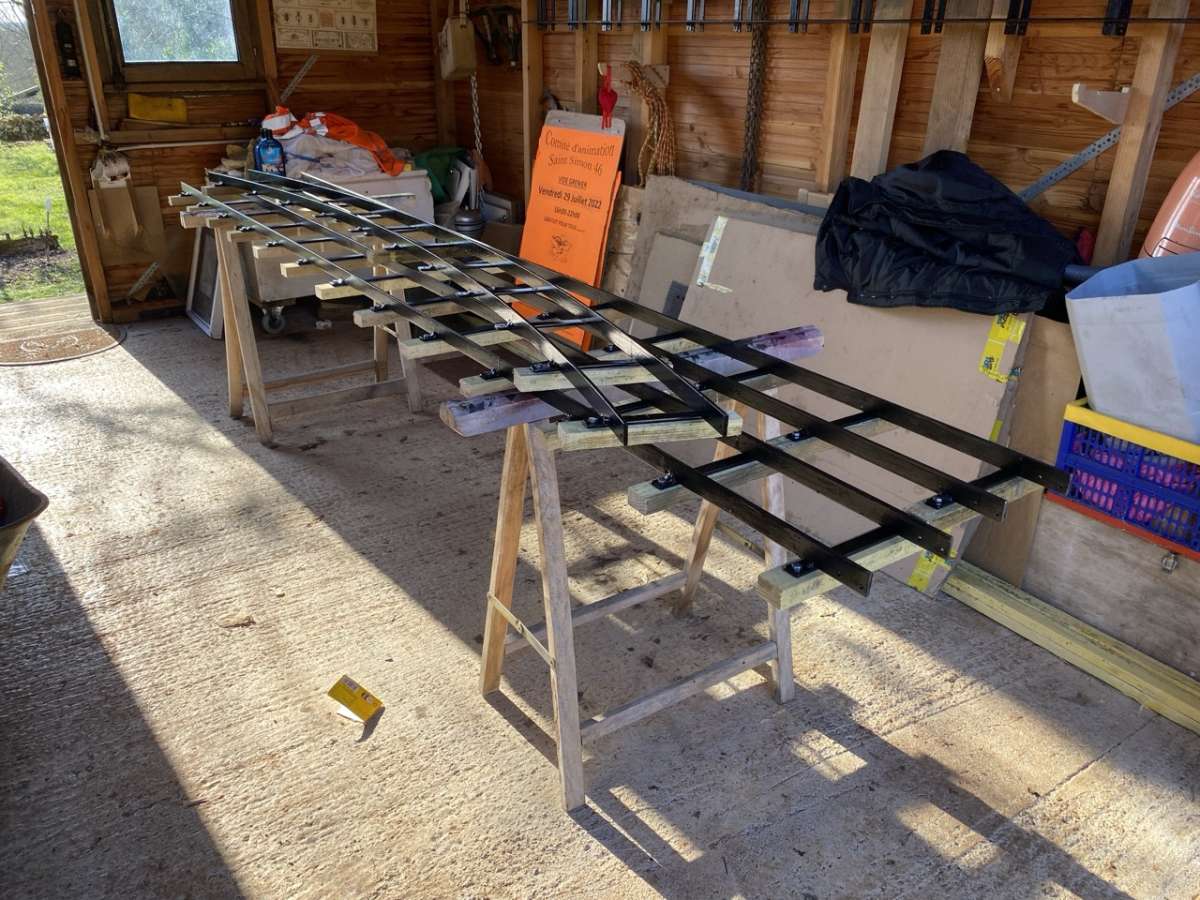
                      Treated 300 sleepers made from roofing battens by immersing in this stuff for 48 hours, let them ‘dry out’ for 7 days, then jig drilled pilot holes for the coach screws.

                      Lifetime wood treatment

                      You can see all sorts of comments for this stuff, but I treated my wooden garage in 2018 with it and there are no signs of mold or fungus etc.

                      Yesterday, I spent a busy afternoon screwing them to the track – that’s another 24meters of track done.

                      Fixing Sleepers Large

                      #711016
                      mike robinson 2
                      Participant
                        @mikerobinson2

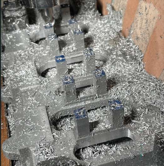
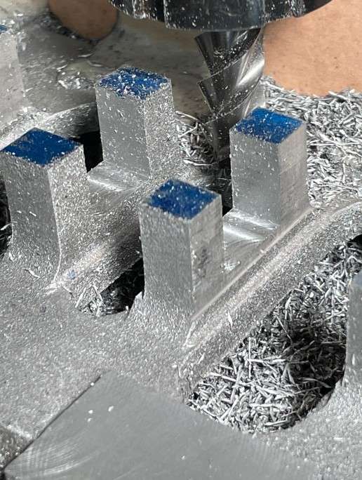
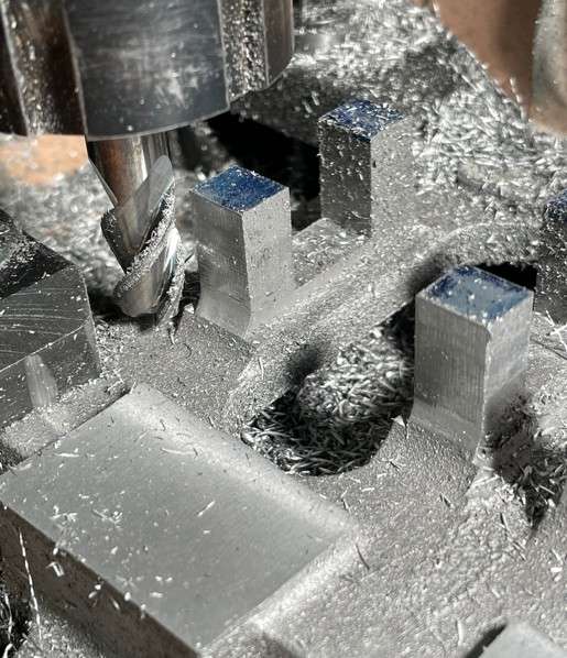
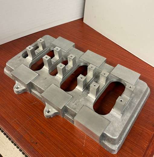
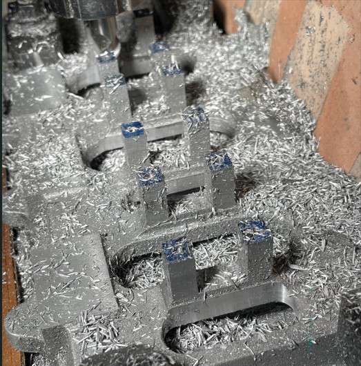
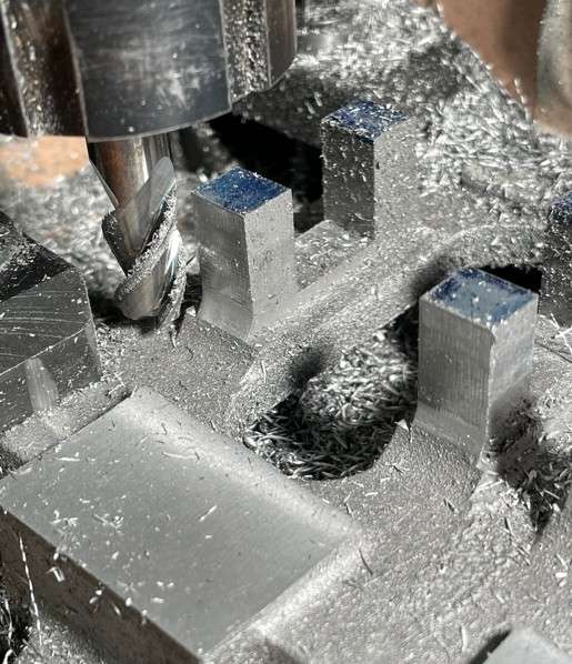
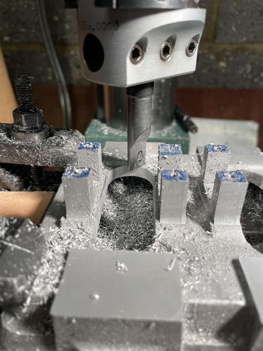
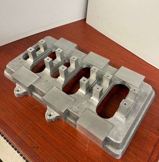
                        Not so much what I did today but an elapsed month. The OB Bolton Triple expansion engine bed plate emerges from lots of swarf despite being frequently vacuumed up at the end of each stage. The aperatures for the crankshaft and eccentics we milled both sides then I used a boring head to generate the radiused ends. Using a large normal HSS milling cutter would have caused a lot of chatter and inaccuracies with coincident faces (and my Tom Senior E Type only has an ER25 chuck and wont take a 15/16″ cutter anyway)

                        1 swarf

                        cuttting the back faces of the main bearing stands to .312″ wide

                        2 edge facing

                        Using a 10mm ballnose carbide to blend the machined faces to the casting line and to the edge of the main bearing reliefs

                        3 ball nose

                        Using the 3 flute carbide alloy cutters was almost silent when cutting and left almost no burrs, even so it will need some careful attention on those very sharp corners. Even with DRO precision, its best to measure a lot, the main difficulty being able to measure the width of the main bearing stands i.e. along the crankshaft centre line. Other than the end stands, you can’t get a normal micrometer in, so checked with my trusty digital callipers. If I did it again I would make some test gauges.

                        4 finished

                        #711027
                        Oldiron
                        Participant
                          @oldiron

                          Lugged home a 1.5 metre long metric vernier. Was in a hell of a state, rusty and seized up. Managed to get most of the rust off using a Stanley blade very carefully. Copious amounts of WD40 and it is now in pieces. All the pieces look OK and have no pitting as such. Needs quite a lot more cleaning but the good thing is that the graduations are still legible. Using 3000 grit paper on all the faces and am very encouraged by the progress over the last 3 hours.

                          #711100
                          mike robinson 2
                          Participant
                            @mikerobinson2

                            yesterday I posted 4 photos and some text right here – and guess what – today they had disappeared – only to re-appear after I posted this text. Strange behavior !

                            #711136
                            mike robinson 2
                            Participant
                              @mikerobinson2

                              so my last 2 posts have disappered again – so am doing this to see if they re-appear

                              #711141
                              mike robinson 2
                              Participant
                                @mikerobinson2

                                testing again – sorry to all – need to do it for the bug report

                                #711148
                                JasonB
                                Moderator
                                  @jasonb

                                  The photos showed OK for me yesterday and I’m seeing your posts today

                                  #711165
                                  Ian P
                                  Participant
                                    @ianp

                                    Yes I saw the photos when they were posted but there is still something odd today.

                                    Earlier today I got an email notification of a thread I’m following, I followed the email link and read the post on the forum page, all OK so far. I then looked at ‘latest replies’ and the last post (top of the list) that it showed was about an hour old, but the reply I had just read had arrived much later. so it was not showing latest post.

                                    I closed the browser and used my usual desktop shortcut (www…..activity-user/) and the latest posts showing were over 2 hours old. I then noticed I was logged out (not by me) but after logging in latest post behaviour was now normal.

                                    Ian P


                                    #711209
                                    Jss
                                    Participant
                                      @jss

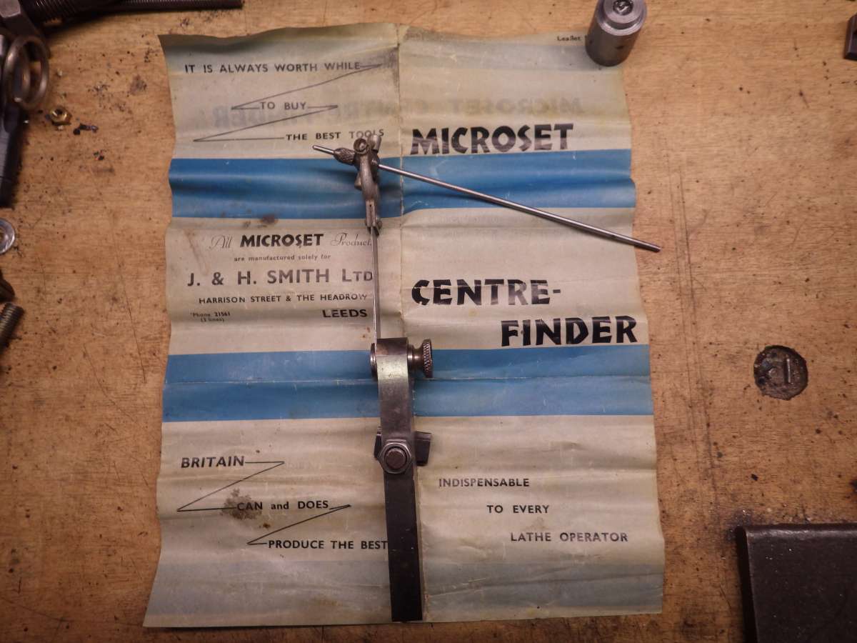
                                      Some considerable time ago I bought this centre finder from a car boot stall.

                                      IMGP1413

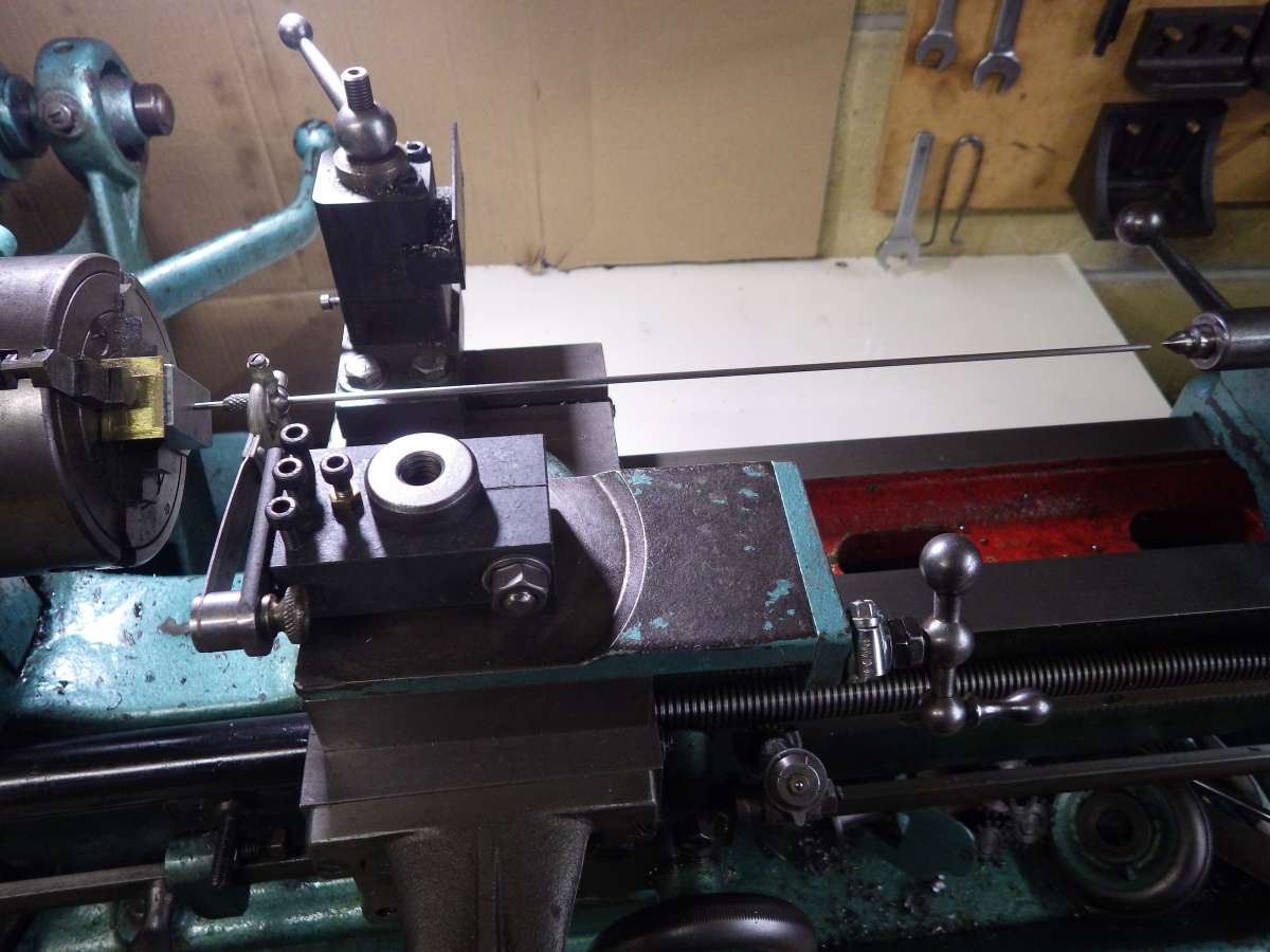
                                      It is designed to be held in the lathe tool holder with the point in a centre pop and you adjust the workpiece until the far end stops wobbling when the work is rotated. Unfortunately the stock is too large to fit the tool holder on my Myford M type. I’ve used it a few times, by bolting it to the cross slide, with some success despite the indicator arm missing the extension piece.

                                      I’ve now modified it to fit my newly made tool holders and fitted a longer indicator arm.

                                      IMGP1415

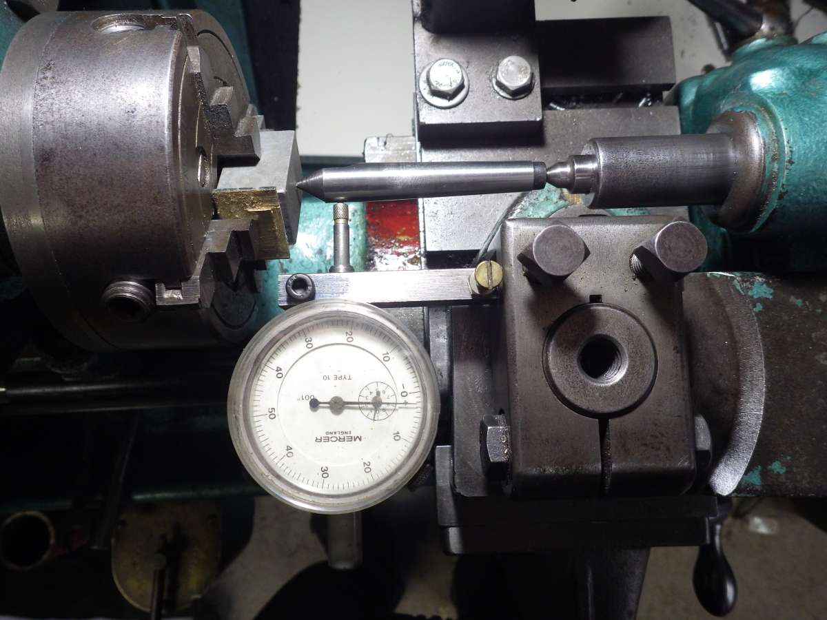
                                      I’ve just tried it out and checked the result using a dial indicator and centre, and it shows the centre pop within 0.002ins of being true. With a bit more fiddling I probably could have got it closer, but close enough for most purposes.

                                      IMGP1411
                                      J & H Smith iron mongers of The Headrow Leeds have long gone, replaced by less interesting shops. On the reverse of the leaflet it states the price as being 32/6. It also states that the spring leaf and gimbal are cadmium plated to resist corrosion. I’ll try not to handle it too much by those parts in future.

                                      John.


                                      #711246
                                      bernard towers
                                      Participant
                                        @bernardtowers37738

                                        I have one similar to that which was bought from a club sale and was told it was made from a kit in the 70’s

                                        #711252
                                        duncan webster 1
                                        Participant
                                          @duncanwebster1

                                          I just have a long thin rod with a point on it. Grip one end in the tailstock chuck and apply the dial gauge near the job with the point lodged on the centre pop. Loctiting a bigger bit near the point end made it better. I’ll take a picture if it is of any interest.

                                          #711354
                                          mike robinson 2
                                          Participant
                                            @mikerobinson2

                                            3rd attempt at posting this, previous 2 just disappeared. Not so much as what I did today, more like over the last month. The O. B. Bolton marine triple expansion engine bedplate casting slowly emerges from a pile of swarf, even if frequently cleaned up after each step.

                                            1 swarf

                                            Using a 10mm 3 flute ball nose carbide cutter to blend in the sides of the main bearing stands to the casting and level with the main bearing reliefs. These cutters are particularly sharp giving an almost silent cut.

                                            2 ball nose

                                            My Tom Senior model E has a 2MT/ER25 collet adaptor fitted and it won’t take a 15/16” dia cutter to clean out the casting radii for the big end and eccentrics clearance. Even if it had, it would most likely caused a lot of chatter, so it was down to the boring head which worked out well.

                                            3 boring

                                            Except for the 2 extreme end stands you can only measure the longitudinal thickness of the middle 4 stands with digital callipers. Some deburring needed now then on to the 6 gunmetal main bearings.

                                            4 finished


                                            #711360
                                            mike robinson 2
                                            Participant
                                              @mikerobinson2

                                              AGAIN apologies to all for the boring duplication – 1st post seems to have re-appeared again. I wont post this again, promise.

                                              #711803
                                              Bazyle
                                              Participant
                                                @bazyle

                                                Not sure if GWR were on strike today as some trains did go along the embankment but Southern kept up a good service for local passengers to and from St Katherine’s station.
                                                Lyn20240204_131623

                                                Weather turned out nice for February and popularity caused an emergency in the catering department so the Secretary was dispatched to the conveniently next door Morrisons for bacon and hot dogs.

                                                #712036
                                                Chris Mate
                                                Participant
                                                  @chrismate31303

                                                  Had a little fight with welding pull. I am busy making a backplate to mount the Ball Turning boring head on. Got two 20mm thick plates and mill &  joined them square together like an angle plate with the top side looking like a U shape engaging the QCTP on both sides instead of the usual one, so double clamped and can go up or down and locked in place. I plan on using this backplate for more things.

                                                  Decided to weld them together instead of bolts then grind and mill to have a seamless joint. I mill a V-groove on top joint, as they were clamped over an angle block. Start welding and ..boom…, it break two small cast clamps, quickly replace with larger ones clamped back to angle plate. After welded and cooled down it had pulled up somewhat with clamps released, like 2.5mm over 100mm, not good, the mistake I made was not to tack the inside, but that would caused a problem clamping it to the angle plate.

                                                  So today I tried to correct the problem, I milled a groove on the inside(Opposite) and weld that as hard as I could. After finished and warm it did not move at all.
                                                  Went to town, and a few hours later when cold, I could not believe it pulled back to square, so now some grinding and very little milling to reface it. This was a relief and surprise, don’t know how much stress is locked up inside however.

                                                  #712329
                                                  Mark Rand
                                                  Participant
                                                    @markrand96270

                                                    Chris:- It might be worth normalising the backplate assembly if long term stability is important.


                                                    Finished scraping the vertical sheers on the ML7 bed. I need to decide whether to do the top of the bed in order to remove the visually unpleasant scratches at the headstock end of the carriages travel even though it will be hard to measure any improvement.

                                                    #712564
                                                    Colin Heseltine
                                                    Participant
                                                      @colinheseltine48622

                                                      I posted the following to What Did you do Today on the 5th.  It appeared to completely vanish into thin air.  So tried again to repost today.

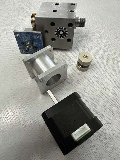
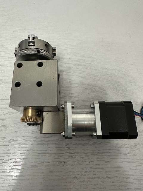
                                                      Machined adaptor spacer to join NEMA 17 stepper motor to Cowells Dividing Head.  Also made backplate cum thrust washer to fit on dividing head.  This was made form a piece of gauge plate.  This will take the wear (better than the aluminium of the spacer) of the spindle on the worm gear.  Next step is to to shorten the stepper spindle and add an 8mm dia bush.  Bore out the HUCO joiner to 8mm both sides.  Make an adaptor to convert the 6mm thread on the worm spindle to the 8mm bore of the HUCO.

                                                      Hopefully by the time all this is done I should have finished assembly of the Arduino Controller which uses Daves (SOD) stepper software.  Just waiting for some 2.5mm brass screws from supplier.

                                                      CowellsDividing Head Pt1Res

                                                      Yesterday finished all adaptors and assembled on the Cowells Dividing Head.  All appears to move freely enough.

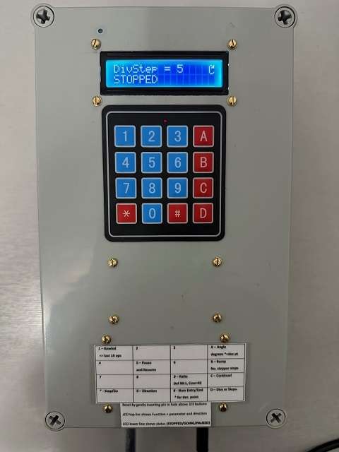
                                                      Finished assembling the Indexer Controller.  It all powered on okay.  Plugged stepper into controller and all works okay.  Main thing to remember is that the ratio of the Cowell Dividing Head is 40:1 not the relatively standard 90:1

                                                      AssembledStepperDividingHeadRes

                                                      AssembledIndexerRes

                                                      Just need to fit on mill and do a proper test.  Will borrow gear cutter of mate and see how I get on.

                                                      Many Thanks to Dave (Silly Old Duffer) for his help.

                                                      Colin


                                                    Viewing 25 posts - 26 through 50 (of 519 total)
                                                    • Please log in to reply to this topic. Registering is free and easy using the links on the menu at the top of this page.

                                                    Advert

                                                    Latest Replies

                                                    Home Forums The Tea Room Topics

                                                    Viewing 25 topics - 1 through 25 (of 25 total)
                                                    Viewing 25 topics - 1 through 25 (of 25 total)

                                                    View full reply list.

                                                    Advert

                                                    Newsletter Sign-up