Posted by petro1head on 07/01/2017 19:19:24:
Did a check and on initial start on the draw is just over 10A settling to a steady 6.5A
Out of interest, how did you measure the peak current, was it with an oscilloscope?
If you are quick enough or brave enough, you could measure the short circuit current with an ordinary digital or analogue meter with the motor stalled. I would not be surprised it it was more than 20A.
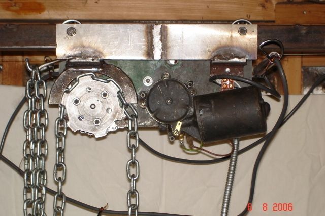
I used car wiper motors on several projects (20 or more years ago) and found that some modifications became essential. Most wiper motor only rotate in one direction and the gearing and bearing arrangements are optimised for that direction. One I used had now provision for the motor spindle (with its integral worm gear) to handle the thrust in the reverse direction. I have also come across the tooth form on the worm and pinion being assymetrical (like a buttress thread) so the gearing efficiency is significantly different in the two directions.
I have no knowledge of the internal design of the wiper motor you have used and its more than possible that the potential problems dont exist in yours.
One other point is that the method of obtaining the two speeds is often by using a third carbon brush positioned so that it uses fewer of the armature windings. Less copper means less resistance so the motor current is much higher resulting in the increased speed. The motor efficiency suffers at the higher speed but the vehicle electrics can cope with it.
Finding a power supply with a PWM output with a high enough current rating to cope with a relatively high current motor might not be easy
My choice would be to use the slow speed brush connection but use a higher than 12V supply (say 15 or 18V)
Ian P
 Gary Wooding.


