Warco WM180 motor control

Advert

Warco WM180 motor control

Home Forums Workshop Tools and Tooling Warco WM180 motor control

Viewing 13 posts - 1 through 13 (of 13 total)
  • Author
    Posts
  • #57681
    modeng2000
    Participant
      @modeng2000
      I am trying to find information about the motor control circuit board fitted to my Warco WM180 lathe. The user speed control on the front of the lathe used to take the chuck speed down to zero as suggested by the speed selection label however now I can not reduce the speed below 200rpm.
       
      There are two preset potentiometers on the cct board, one for min revs and the other for max. The min rev setting is at the lower limit of rotation so there is no more adjustment available.
       
      The information I have from the circuit board is that it is by Best Control Inc (Taiwan) and is a BC 2000TA DC motor control board.
       
      I have in the past asked Warco if they would supply me with information about setting up the motor control board but to no avail. It seems a bit over the top to take the lathe back to them or to call them out for a service call to adjust a nominally working machine.
       
      Some while ago I used the lathe to wind the solenoid coils for my ME Clock but I couldn’t now as it runs too fast.
       
      John 


      Edited By modeng2000 on 28/10/2010 16:39:25

      Advert
      #16584
      modeng2000
      Participant
        @modeng2000
        #57682
        Chris Kelland
        Participant
          @chriskelland71558
          Hi John,
           
          I take it you have rung Warco?
           
          If not give them a ring 01428 682929 extension 209  and ask to talk to Eric or Chris they are the tech engineers and very helpful.
           
           
          Chris.
          #57683
          Chris Kelland
          Participant
            @chriskelland71558
            Hi John,
             
            You could also look at this link, there is a bit of info on the control board.


            Chris
            #57684
            john swift 1
            Participant
              @johnswift1
              Hi John
               
              if Warco can’t help
               
              have a look at the control board
              If your lucky the speed control board will have preset’s for  the maximum and minimum speed marked on the pcb 
              (make a note of the position before adjustment of the minimum speed)  
               
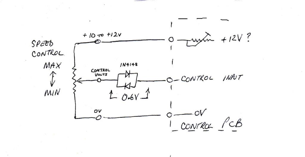
              if not and you have the wiring diagram for you machine
              you could disconnect the +10v or +12v supply form the speed control to prove
              that with a control voltage of 0v the speed is 0 rpm
               
              two diodes can be used to give a 0.6v volt drop to the control voltage to give a small reduction in speed
               
              I’ll post a diagram


                     John 
                

              Edited By john swift 1 on 28/10/2010 17:48:41

              Edited By john swift 1 on 28/10/2010 17:49:22

              #57695
              john swift 1
              Participant
                @johnswift1
                missing from previous post
                 
                with the speed control fully anticlockwise the control voltage may not be zero
                (the mechanical end stop may stop the wiper reaching the end of the resistive track)
                 
                also the minimum and minimum speed presets interact
                 
                so far I can not find the circuit of KB Electronics speed controls used in your lathe
                 
                 
                     John 


                #57699
                modeng2000
                Participant
                  @modeng2000
                  Thanks for the replies, all very interesting.
                  The minimum preset is at minimum so I can’t get any more reduction from there. If the max and min resets interact I might be able to ‘shift’ the speed control range down by careful adjustment but don’t hold much hope for this aproach. Something has changed because I was able to reach almost zero speed when the lathe was new.
                   
                  Chris, I’ll ring Warco again, it is now some time since I last tried and perhaps I did not speak to the best person then. The link to andysmachines is quite informative, thanks.
                   
                  John, I have tweeked the speed presets and know where they were before touching them. however this has not helped to reduce the lowest speed. I was hoping for a circuit diagram of the pcb so I could understand how the speed presets function.
                   
                  John
                  #57705
                  john swift 1
                  Participant
                    @johnswift1
                    Hi John
                     
                    found a low res circuit that may help


                    the max speed preset pot sets the voltage across the speed control
                     
                    the min speed preset adjusts a bias voltage to the first op amp
                     
                    it may be worth checking all the electrolytic capacitors on the board
                     
                    ( if you can measure the ESR ) 
                     
                     
                          John

                    Edited By john swift 1 on 28/10/2010 22:03:27

                    #57738
                    modeng2000
                    Participant
                      @modeng2000
                      Things are not quite like your circuit John. It turns out that the 3 pots, Max, User control and Min are all in series across the supply rails. So with the Min at zero volts I suspect there has been a change elsewhere in the circuit.
                       
                      I shall go round with my Fluke and make sure that the zero setting is indeed zero volts.
                      John
                      #57755
                      john swift 1
                      Participant
                        @johnswift1
                        Hi John ,
                         
                        so far i’ve only found a picture of your control pcb
                         
                        but have not found the circuit of it or similar looking kb electronics control
                         
                        it looks like you will end up reverse engineering your board !
                         
                        as I did a the start of the year , with my CL300 minilathe
                         
                            John
                        #57757
                        Billy Mills
                        Participant
                          @billymills
                          John
                           
                          Don’t know your machine but wonder if there is an opto tacho connected to the corner connector. Would suspect that a dirty or failed slot sensor could produce the fault. With no tacho signal the controller would run above the set min speed. Would never rush in to modify stuff without understanding what we are dealing with.
                           
                          Regards
                          Alan
                          #57759
                          modeng2000
                          Participant
                            @modeng2000
                            Alan,
                             
                            The opto tacho is working normally in that it displays the actual spindle speed changing as the cutting load varies. As far as I can tell the tacho is independant of the motor control circuit.
                             
                            John
                            #57760
                            modeng2000
                            Participant
                              @modeng2000
                              John,
                               
                              Now I have a fair idea as to what is going on with the motor control I could end up reverse engineering. At least it seems to use a quad op amp LM324, one of my favourite chips.
                               
                              John
                            Viewing 13 posts - 1 through 13 (of 13 total)
                            • Please log in to reply to this topic. Registering is free and easy using the links on the menu at the top of this page.

                            Advert

                            Latest Replies

                            Viewing 25 topics - 1 through 25 (of 25 total)
                            Viewing 25 topics - 1 through 25 (of 25 total)

                            View full reply list.

                            Advert

                            Newsletter Sign-up