WARCO WM-250 lathe family and WM16 mill – 001

Advert

WARCO WM-250 lathe family and WM16 mill – 001

Home Forums Workshop Tools and Tooling WARCO WM-250 lathe family and WM16 mill – 001

  • This topic has 374 replies, 62 voices, and was last updated 6 July 2020 at 23:20 by Cabinet Enforcer.
Viewing 25 posts - 151 through 175 (of 375 total)
  • Author
    Posts
  • #130550
    Rik Shaw
    Participant
      @rikshaw

      When I had my WM16 delivered my next door builder neighbour and his burly labourer popped it up on to its stand (an old kitchen cupboard) with the greatest of ease.

      Not so the WM 250V-F lathe though, that took three blokes.

      Rik

      Advert
      #130552
      mechman48
      Participant
        @mechman48

        I hoisted my mill onto the stand using an engine hoist & a 1 ton sling wrapped around the head, butted up against the column, with everything locked up tight, & a little help from Finance director (SWMBO). The same method applied to the WM250.

        Lifting method

        no damage done whatsoever.

        George

        Edited By mechman48 on 23/09/2013 19:00:25

        #132635
        Rik Shaw
        Participant
          @rikshaw

          I am planning on buying a rotary table at the Leamington Spa show this week. Only thing that puzzles me is that there is a 2MT in the centre of these types of table. What would I fit in there? All of the rotary tables I have used in the past have had a simple parallel bore for clocking up purposes.>>

          WARCO have cautioned me not to try to use anything bigger than their 110mm dia. HV4 on my WM16 mill (I'll find out exactly why at the show). What I'd really like though in order to take advantage of the table width is a low profile 8" dia. job but have not seen anything like that advertised any where – it might be prohibitably expensive but I can dream can't I?>>

          Rik>>

          #132642
          Phil Ashman
          Participant
            @philashman88468

            Rik,

            I use a Vertex HV6 on my WM-16, and I'm glad I didn't go for anything smaller. The table has a 2MT in the centre, and it's ideal for taking a chuck adapter. The ability to unscrew the chuck from the lathe, complete with job, and screw it to the rotary table, and then back again, is a facility I use over and over again.

            Even with the chuck mounted on the rotary table,+ job, there's usually plenty of clearance from the cutter.

            Phil

            #134000
            Rik Shaw
            Participant
              @rikshaw

              ~~I have almost completed the installation of the economy WARCO DRO scales on my WM16 mill and would like to point out that not all jobs like this are as simple as one might think.

              First and (I wasn't thinking) it did not occur to me that the scale bars need to be parallel to the top of the table to get the best accuracy. OK, it seems obvious now but Michael the fitter at WARCO made the penny drop for me. Using a clock from the table sorted that problem out and the X scale was fitted without to much trouble.

              Y scale was a b**tard. First thing identified was that the scale was about 6mm to long. Had read that this can be got round by hack sawing to length. OK, so here goes with a new ,expensive German bi-metal blade I went for it. Half way through the very tough scale it decided to work harden itself and I had to resort to an ALDI version of a dremmel fitted with an elastic wheel to finish the cut.

              Next, marked out the holes for the scale on the machine casting for the 6mm fixing screws and using a 3mm pilot drill attacked the casting. Zilch……..all I did was remove the paint! The casting, front and rear was as diamond —– "chilled" is not sufficient to describe how hard it was. An hour or so later using the ALDI dremmel thing loaded with a 3mm diamond burr I managed to plunge in to approx 4mm deep and this was enough to allow the tapping drill to get a bite and find the soft stuff – phew!

              Fitted the scale and found the supplied bracket for the readout sensor was unusable. Spent the next two hours making and offering up an ally fixing bracket to replace it. Finally got it right and it was time to drill the third and final hole in the casting to fix it. Would you believe it? The bl**dy casting was chilled again! More diamond grinding and eventually drilled and tapped for the fixing screw.

              Last job was to fix the XY remote display to the top of the 'lecrix box and connect the USB cables to the scale sensors.

              Hefty slap to the forehead as I realised that the USB plug in the X reader was going to foul on the base casting and damage either the cable or the reader.

              In order to overcome this prob I will have to use a 90 degree USB thingy which I have just ordered from a UK Ebay website only to be informed that it will take up to 10 days to be delivered from somewhere in the Orient.

              Having been retired now for two years I had hoped that "stress" would be something that yuppies suffered from – looks like I was wrong.

              Rik dont know

              #134012
              Rik Shaw
              Participant
                @rikshaw

                Was unable to edit the previous post but must add that in failing to drill the casting at the rear I attempted to use a carbide tipped drill which at high speed, bent at 90 degrees and ripped the rubber ways protector to shreds – some cheap rubber car mats from the pound shop might sort it OK.

                #134069
                mechman48
                Participant
                  @mechman48

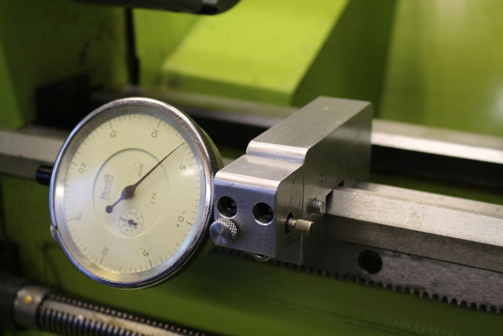
                  Decided to make a tailstock fitting to attach a digital tyre depth gauge to my tailstock, to get a better reading for depth drilling, a lot of members will have something similar no doubt. Used some ally from my scrapbinium box, some neodiminiminum…? …. 'earth' magnets & some epoxy resin. It gave me a chance to use my rotab' for the first time since I got it a year ago so it was a learning curve as well as making something from my 'toduit' list.

                  The only addition to the digi gauge was to fabricate a small steel plate on the back of the gauge at the front end which had 4 small magnets epoxy glued on & 6 smaller stacked magnets at the rear end (2 stacks 3mm x 1mm) this was then just placed onto the tailstock. I glued a 6 x 1 magnet onto the back of the clamp which when attracted to a small magnet I'd fitted to the stem of the gauge sometime earlier gave an extra strong magnetic pull.

                  tailstock dro (1).jpg


                  tailstock dro (2).jpg

                  One less item on the list…now what's next?

                  Cheers

                  George


                  Edited By mechman48 on 29/10/2013 20:00:42

                  Edited By mechman48 on 29/10/2013 20:26:31

                  #134133
                  Rik Shaw
                  Participant
                    @rikshaw

                    bed stop.jpgNovel way of using a depth gauge George, let us know how you get on with it.
                    I have made an improvement to your bed stop design. The "piggy backed" piece of ally is secured by 2x 5mm capheads.  I can now use a DTI without removing the original threaded stop.


                    Edited By Rik Shaw on 30/10/2013 16:14:26

                    Edited By Rik Shaw on 30/10/2013 16:15:07

                    #134151
                    mechman48
                    Participant
                      @mechman48

                      I like it, thanks for the update, much prefer to see nice large digi' numbers though what with my eyes and all, nice mod never the less, will keep in the memory bank… memory bank ! … where's that, & what interest rate are they paying?… ho hum, retiree's humour face 22.

                      George

                      #134153
                      Thor 🇳🇴
                      Participant
                        @thor

                        Hi Rik,

                        I like your "piggy backed" bed stop solution, it's on my "to do" list.

                        Thor

                        #134359
                        Rik Shaw
                        Participant
                          @rikshaw

                          ~~I had to return my new QCTP to WARCO as the locating bore had been machined oversize.

                          Today I have received a replacement from them and the bore is now the correct size although I had not expected they would send me out someone else's QCTP which bears obvious signs of use i.e. deep scratches and various dings. The thing that bothers me most though is that when locking the post into position – and I mean TIGHTLY – I can still grasp the block with both hands and turn it anti-clockwise albeit with difficulty.

                          I had not tried the hands turning test with the original block but I do know that when I tried cutting a knurl some weeks ago by plunging in with the cross slide (ally was the material) the knurling tool pushed of because the block was rotating anti-clockwise.

                          I would mention that it is not a case of the threaded hole in the clamping handle bottoming out on the top slide thread – it has plenty of spare threads. Also, I have blued up the base of the QCTP block and rotated it on the top slide – it shows that it is mating up OK

                          Anyway, I can always revert to using the standard tool post with its spring loaded locking pin to do future knurling but it still bothers me that the QCTP can rotate in this way. Your comments would be most welcome of course.

                          Rik

                          #134378
                          Thor 🇳🇴
                          Participant
                            @thor

                            Hi Rik,

                            sorry to hear about your QCTP troubles. When the QCTP block is clamped to the top slide, it shouldn't rotate of course. Seems to me that you have to return this QCTP too.

                            I made my own tool post for my new 290F lathe, after G. Carlson's ideas, they work well and I have not had any problem with them rotating. Since I got the steel for the tool holders for free my only expense has been some allen screws. I have to remove the clamping handle though to exchange tool holders.

                            Thor

                            Edited By Thor on 02/11/2013 05:49:31

                            #134389
                            Sub Mandrel
                            Participant
                              @submandrel

                              Hi Rik,

                              If it is just a standard metal to metal contact either the surfaces are too smooth or the size of nut/thread isn't  enough to give the force needed to hold a tool at that radius.

                              Consider a thrust roller bearing (they are very thin) under the locking nut. I think Arc Euro may have these on clearance?

                              Or a piece of paper under the toolpost – bit of a bodge I know but…

                              Neil

                              Edited By Stub Mandrel on 02/11/2013 10:03:52

                              #134499
                              mechman48
                              Participant
                                @mechman48

                                Hi Rik

                                Surprised that Warco have sent you someone's reject / used post, it makes that second hand, have you paid full price for it? I would give them a call & arrange some sort of refund / credit note.

                                Considering they had machined the replacement then I would look at drilling a anti rotation pin hole through the post / block & into the cast compound slide & make a pin to suit. My QCTP is one I kept from my 3-1 machine & it is a Bison copy of the Myford which already has a hole machined in before it was heat treated. I have drilled 2 locating holes through this into the casting, one position to use as normal & another to allow me to use the backside of the post if I need that extra outside diameter machinability if you get my drift.


                                anti rotation pin (1).jpg

                                The other location hole is under the top right corner allowing me to turn the post 90* anticlockwise & bring the left side tool holder location to the rear (bottom of pic) to give me approx' an extra 1" or so OD machining capability.

                                Cheers

                                George

                                Edited By mechman48 on 03/11/2013 11:11:24

                                #138589
                                Mark P.
                                Participant
                                  @markp

                                  Hello all,has anyone else had problems when lowering the head on their WM16 mill? I find that it judders or sticks on the way down. I have checked and adjusted the gibbs but nothing seem to to cure it, I have thought about fitting a flipping strong spring to put it under some load. Any thoughts?

                                  Mark P.

                                  #145486
                                  john kennedy 1
                                  Participant
                                    @johnkennedy1

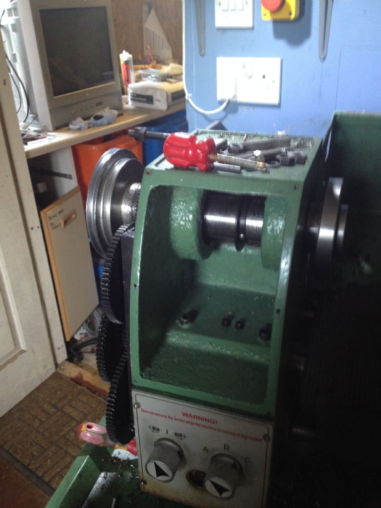
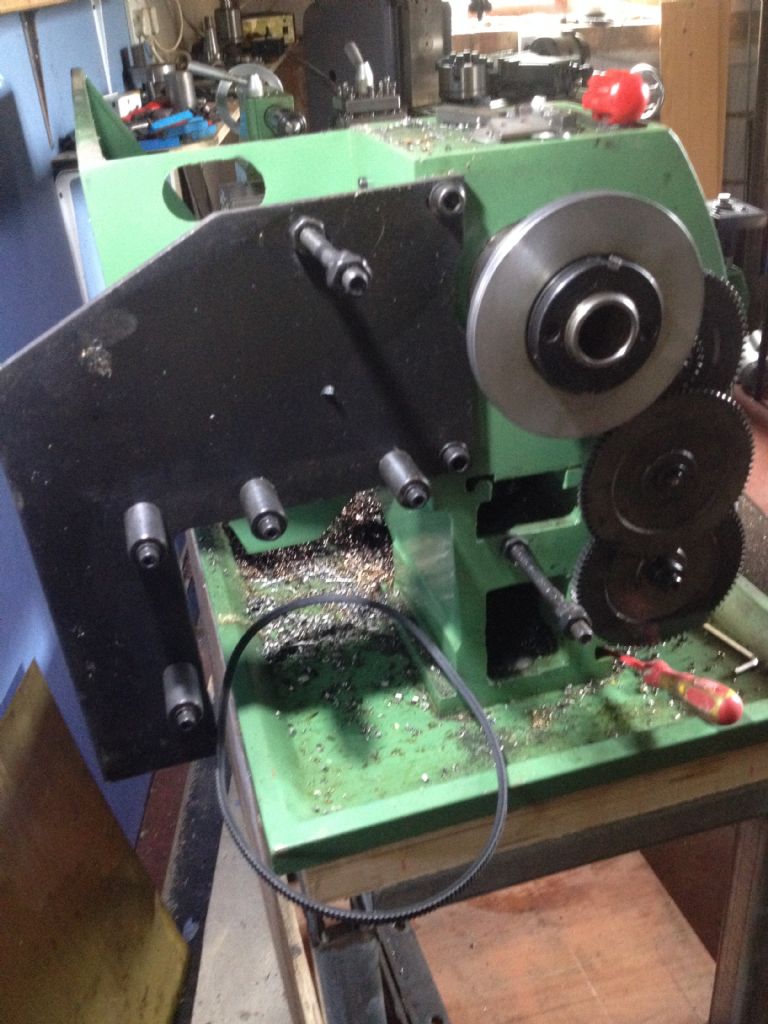
                                    006.jpgI've had my wm250 for over 4 years now and I've been happy with it other than the variable speed.Its hand being able to turn the speed up and down whilst on the move but the torque is pretty poor at low speeds.The motor soon gets hot with a low fan speed and you have to keep stopping when it starts to smell that unmistakable smell.

                                    I decided to splash out £100 and get a qctp from rdg.Beautiful bit of kit,but of course it needs slight modification. Following the way its done on this link http://www.cign.org/wm250qctp2.html I had to turn a short 84mm plinth for the post to stand on. All I had was a piece of about 4" so I started turning that down. What a joke could only put on 0.5 mm cut on the dial,that's 0.25 mm deep cut. The lathe would stall on anything less than 150 rpm so next thing I know the rcd tripped. My old Myford,as worn as it was would have made short work of it in backgear. Don't know if I got a bad machine or what. Is anyone getting any better performance ??

                                    what iv'e decided to do is go 3 phase with inverter as per my milling machine. Started stripping the dc stuff out.

                                    Went on ebay this morning looking for a suitable motor and inverter and after a couple of clicks my pp account suffered to the tune of nearly £300, but worth it I hope. 005.jpg

                                    #145498
                                    Rik Shaw
                                    Participant
                                      @rikshaw

                                      Hello John

                                      Results from my wm250-vf a few minutes ago:

                                      I chucked a piece of unidentifiable 60mm dia. bar. It was not mild steel – something quite a bit tougher.

                                      Set the speed controller to 126 r.p.m and using a tipped tool applied a 1mm cut (2mm of dia.). Set auto feed going and turned down the OD of the bar a short distance. The machine struggled/faltered but did OK.

                                      Changed the tool to a tangential holder – the tool bit still a little blunt from a previous job – and repeated the above. This time the tool cut much easier and with no speed judder as with the tipped tool. The only thing I noted was that the second cut with the tangential slowed the speed from 126 down to 106.

                                      I don't think I'd like to go any deeper than 1mm using the above scenario.

                                      I'll leave you to draw your own conclusions.

                                      If you need any more help comparison wise just shout although it looks like you have the matter in hand with the new motor.

                                      Rik

                                      #145501
                                      john kennedy 1
                                      Participant
                                        @johnkennedy1

                                        Thanks Rik, Yes a lot better than mine was doing I think. Anyway I've gone past the point of no return now so fingers crossed the motor will squeeze in. I'll keep the gear ratio low, about 700 to 800 rpm at 50 htz so there will be plenty of grunt low down. In 4 years I've never felt the need to go into the 1000 to 2000 speed range. I'll put some more pictures up when the goodies arrive. John

                                        #145508
                                        Ed Duffner
                                        Participant
                                          @edduffner79357
                                          Posted by Mark P. on 23/12/2013 15:18:53:

                                          Hello all,has anyone else had problems when lowering the head on their WM16 mill? I find that it judders or sticks on the way down. I have checked and adjusted the gibbs but nothing seem to to cure it, I have thought about fitting a flipping strong spring to put it under some load. Any thoughts?

                                          Mark P.

                                          Hi Mark,

                                          I had an issue with cutters having a slight bounce when milling the top surface of stock, causing grooves in the finish. I thought I'd adjusted the gibs to take care of it and it did improve a little but when I looked at it again I found I had to lift the head assembly slightly to get a bit more tightness on the gibs.

                                          Cheers,
                                          Ed.

                                          #145512
                                          JasonB
                                          Moderator
                                            @jasonb

                                            I was doing some 9.5" CI flywheels last week on the 280, 0.025" DOC ( 0.64mm) with tipped tools no problem but I do run it at a reasonable 250-300rpm.

                                            Like John I've only used the higher speed range about twice and that was when I first got the lathe

                                            Interesting to note that Warco have just started to do the 280 with an inverter rather than the DC motor and upped the HP.

                                            #145516
                                            Mark P.
                                            Participant
                                              @markp

                                              Hi Ed, will try taking the weight off the head and then adjust the gibs.

                                              Will Warco offer an inverter upgrade for the WM250 do we think?

                                              Mark P.

                                              #145531
                                              john kennedy 1
                                              Participant
                                                @johnkennedy1
                                                Posted by JasonB on 28/02/2014 16:06:13:

                                                Interesting to note that Warco have just started to do the 280 with an inverter rather than the DC motor and upped the HP.

                                                That is interesting. I've gone up a bit to a 1.1kw motor for a bit more wellie. devil

                                                #145960
                                                Rik Shaw
                                                Participant
                                                  @rikshaw

                                                  rear tool post 001.jpg

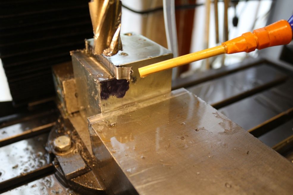
                                                  Started work this morning on a rear tool post for the WM-250-VF using this block of steel which will elevate the original tool post (I use a QCTP these days) to the correct height.

                                                  First thing to do was to remove 9mm from one end with the WM-16 milling machine. As you can see in the photo I have taken the first cut of what was going to be several.

                                                  Now for the main point of the post. By the time I reached the end of the cut the shed was filled with the pong of burning motor and several strange electrical "popping" noises came from the motor although it made it OK to the end.

                                                  The cut is approx. 13mm wide x 8mm deep taken with a fairly new and sharp 20mm dia. Dormer HSS end mill. Speed adjusted to 450 rpm I hand fed at a fairly easy rate and it took maybe twelve minutes to get from one end to the other. By this time the motor casing was very hot indeed certainly to hot to continue further work.

                                                  I have stopped trying to do this on the mill and intend doing the job using the four jaw chuck on the lathe. I do not want to destroy the mill.

                                                  I am not surprised by this overheating as it has happened before. My CY90 band saw also gets very, very hot when cutting through something similar – even with a new Bi-metal blade fitted.

                                                  It seems as though I might be expecting to much from my little mill – what do you think?

                                                  Rik

                                                  P.S JasonB – thanks for stopping me from selling my original tool post a while back its going to come in handy after all.

                                                  #145961
                                                  JasonB
                                                  Moderator
                                                    @jasonb

                                                    I'd say you are taking far too big a cut for that size of mill and judjing by the large burr on the block your cutter is blunt

                                                    #145962
                                                    Anonymous

                                                      A 20mm diameter end mill at 450rpm gives a cutting speed of 93fpm; very reasonable for low carbon steel.

                                                      From the dimensions given for the cut I estimate that the length of the block is about 60mm. That gives a total volume of metal removed of 0.38 cubic inches. If the cut took 12 minutes then that is 0.032 cubic inches per minute. A useful rule of thumb is that 1hp will remove 1 cubic inch of material per minute in low carbon steel. So for the cut in question the power required should be negligible, a few tens of watts. If the motor got hot then it would seem there's something wrong with the motor or drive?

                                                      As an aside I would suggest that the feedrate was at least an order of magnitude too slow. Assuming a 4 flute cutter the chip load was about a tenth of a thou. I'd be up at a few thou per tooth. I would think that the cutter might have spent more time rubbing than cutting; did it get hot too?

                                                      Regards,

                                                      Andrew

                                                    Viewing 25 posts - 151 through 175 (of 375 total)
                                                    • Please log in to reply to this topic. Registering is free and easy using the links on the menu at the top of this page.

                                                    Advert

                                                    Latest Replies

                                                    Viewing 25 topics - 1 through 25 (of 25 total)
                                                    Viewing 25 topics - 1 through 25 (of 25 total)

                                                    View full reply list.

                                                    Advert

                                                    Newsletter Sign-up