Warco GH600

Advert

Warco GH600

Home Forums Manual machine tools Warco GH600

Viewing 25 posts - 151 through 175 (of 209 total)
  • Author
    Posts
  • #457957
    Dan_B
    Participant
      @dan_b

      My current set was mounted on a Myford backplate so not quite that simple. I cant remember what size i choose now, need to get in the workshop and have a look.

      I'm sure i can sort something out though or I may decide to sell the collet set with the Myford.

      Dan

      Advert
      #457963
      Jed Martens
      Participant
        @jedmartens56976

        As Howard says, the chucks bolt onto the flange of the spindle, there is no thread. There are holes for both 3 and 4 bolt patterns.

        For some reason the 4 jaw chuck was supplied with a back-plate, but the chuck will bolt directly to the flange, so I ditched the back-plate.

        I use ER32 collets, and purchased a collect chuck from ARC. Again, this bolts directly to the spindle flange. So I haven't had to use back-plates at all.

        The internal taper of the spindle is 4MT, but aside from a dead centre (supplied with the lathe) I haven't made use of this.

        Jed

        #457964
        not done it yet
        Participant
          @notdoneityet

          Sell only the myford back plate with the lathe?

          Make a new back plate to fit the ER collet chuck to your new lathe? If you were very lucky, the chuck might even bolt up directly to the flange…. but I would (always) make a plate to accurately fit the chuck spigot (and flange spigot, if it has one) and face it in situ to be sure of it running true.

          You are likely to benefit from having an ER system for the new lathe and selling, just to buy again, is not exactly sensible In my book – unless you intend to up-grade on quality.

          #461543
          Triumphboy
          Participant
            @triumphboy

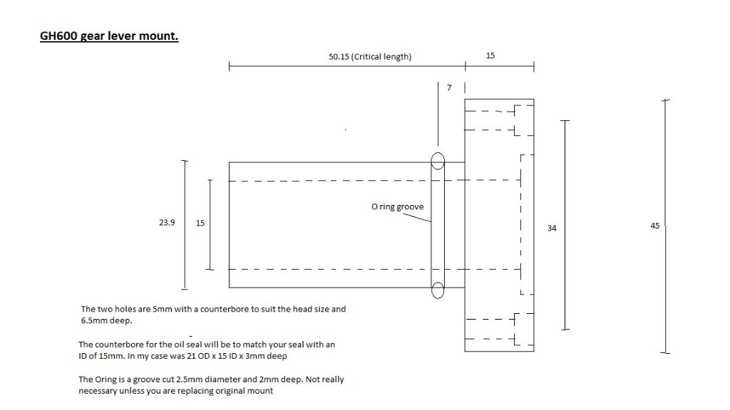
            GH600 Lathe Oil Leak Repair


            After my previous rambles about oil leaks, I finally completed the detection, thought process and solution for this, the largest of the leaks.

            I have produced a PDF document explaining the process I used to sort out this oil leak. I tried to attach it here but I couldn't figure out if you could or couldn't add attachments.

            If anyone is interested, I can email it to you and if you decide you want to go ahead, I can post the replacement lever mount that needs fitting to allow you to modify your unit, as a loan unit while you machine yours.

            All of this took many hours and became a project that I / we shouldn't have to do but there you go!

            Hopefully, these steps will provide help to someone that identifies the same issue on their machine.

            The O ring prevents a bit of the leakage but most of the oil was coming out of the lever hence the oil seal.

            All the dimensions are in the PDF.

            Note:- The O ring is a 2.5mm cross section 19mm ID (Slightly stretched) and the front Oil seal is 21mm OD x 15mm ID x 3mm thick.


            Best regards and good luck. Triumphboy. J

            Edited By Triumphboy on 01/04/2020 16:18:34

            Edited By Triumphboy on 01/04/2020 16:32:09

            #461544
            Triumphboy
            Participant
              @triumphboy


              capture.jpg

              Edited By Triumphboy on 01/04/2020 16:31:02

              #461559
              Triumphboy
              Participant
                @triumphboy

                #461560
                Triumphboy
                Participant
                  @triumphboy

                  #461561
                  Triumphboy
                  Participant
                    @triumphboy

                    #477325
                    IRT
                    Participant
                      @irt

                      Has anyone modified their GH600 to lock the cross-slide yet?

                      #477721
                      Dan_B
                      Participant
                        @dan_b

                        I have been looking through Grizzly lathe manuals seeking better instructions than the Warco manual and came across a cross slide lock screw on a similar looking setup. It is the usual format of gib strip lock screw.

                        cross slide lock example

                        I have had my GH600 two months now and still have a few teething issues to get through as i haven't had much time to fiddle yet.

                        One problem i have is with surface finish. So far i haven't managed to eliminate the rough finish shown here (its worse than it looks when you run your nail over it and feels like a fine thread):

                        Brass Test

                        I have made the following checks:

                        1. Tool height – tried it bang on centre and 0.4mm below, same outcome
                        2. Tool overhang – absolute minimum
                        3. Speed/feed – tested speeds from 500-1500rpm with no improvement, feed rate 0.044mm
                        4. Cut depth – 0.05mm to 0.2mm, same results.

                        I'm using an insert tool with a fresh edge, it is a TPMR 110304.

                        I have reset all of the gib strip, i would say that i have the top slide too tight, the cross slide perfect and maybe an issue with the saddle.

                        I have set the gib strip at the rear of the saddle and snugged it up quite a bit from the factory setting. I tested with a DTI on the top of the saddle to see if there was any lift and measured 0.01mm. Should i attempt to tighten this gib further?

                        If i move the DTI and test the saddle at the front i can measure 0.025mm of lift but don't see anyway to adjust this? Here is a diagram, it would be parts 45 and 46 that would need to be adjusted. Is this normal?

                        saddle diagram

                        My other thought was spindle preload so with a DTI on the top of the register flange and a large drill for leverage I measured 0.01mm of lift. I could equally measure a further 0.01mm in the downwards direction from neutral so i'm not sure if it is deflection rather than bearing clearance. Again does this sound OK or is the movement excessive? I didn't expect any movement so close to the bearing.

                        Any advice on what to try next or where I'm going wrong would be appreciated.

                        Incidentally parting off has been a terrible experience so far and i suspect connected to the surface finish issue.

                        Kind regards

                        Dan

                        #477738
                        Martin Connelly
                        Participant
                          @martinconnelly55370

                          Feed rate seems very low. Using an insert you need to make it work and not rub. Try a feed of 0.125mm/rev. For small cuts the depth of cut should be similar to or below the radius of the insert but not too small. These inserts have 0.4mm radius so try 0.2mm DOC. Tools should be on centre height. RPM depends on the diameter of the stock. If the diameter of the stock is 10mm then try 1500 RPM if that is the fastest your lathe goes. Bigger diameter reduce RPM eg 20mm (double 10mm) half the RPM.

                          There is a thread that is accessed from the home page under workshop/processes I think regarding speeds and feeds.

                          Martin C

                          Speeds and feeds thread

                          Link added

                          Edited By Martin Connelly on 05/06/2020 17:59:22

                          #477739
                          SillyOldDuffer
                          Moderator
                            @sillyoldduffer
                            Posted by Daniel Bird 1 on 05/06/2020 17:04:29:

                            One problem i have is with surface finish. So far i haven't managed to eliminate the rough finish shown here (its worse than it looks when you run your nail over it and feels like a fine thread):

                            I have made the following checks:

                            1. Tool height – tried it bang on centre and 0.4mm below, same outcome
                            2. Tool overhang – absolute minimum
                            3. Speed/feed – tested speeds from 500-1500rpm with no improvement, feed rate 0.044mm
                            4. Cut depth – 0.05mm to 0.2mm, same results.

                            I'm using an insert tool with a fresh edge, it is a TPMR 110304.

                            Any advice on what to try next or where I'm going wrong would be appreciated.

                            Incidentally parting off has been a terrible experience so far and i suspect connected to the surface finish issue.

                            Kind regards

                            Dan

                            Checks look reasonable but before assuming the worst what sort of steel is it? I had endless trouble starting out because gremlins filled my scrap-box with nothing but carp metal! Quite a lot of alloys are downright awkward and it can be tricky to get a good finish on ordinary mild-steel.

                            All bets are off if you don't know what the metal is. If uncertain, order some EN1A or, even better, EN1A Pb. In the event one of those refuse to cut nicely with a sharp insert, then it's definitely time to look at the machine.

                            Dave

                            #477743
                            Martin Connelly
                            Participant
                              @martinconnelly55370

                              This is a link to the Little Machine Shop speeds and feeds calculator. Try it for speeds and feeds.

                              Little Machine Shop

                              Martin C

                              #477744
                              Dan_B
                              Participant
                                @dan_b

                                The material pictured was brass which seemed to cut OK, lots of fine chips. I also tried a piece of aluminium and got the same results.

                                The diameter is 10mm. I tested speeds up to 1500RPM and feed up to 0.9mm/rev.

                                I must say i have very little experience with tip tools so maybe this is some of my problem. The tool is as close to perfect centre.

                                Is this a less than ideal insert for brass or aluminium?

                                I will try a HSS tool tonight and also i thought to try a cut with the saddle locked and feed from the top slide – that should eliminate any issues caused by the saddle gib.

                                I do have some bright mild steel recently bought from macc models so this should also be good for a test.

                                Thanks for the suggestions so far.

                                Dan

                                #477748
                                Howard Lewis
                                Participant
                                  @howardlewis46836

                                  0.044 mm / rev is a fine feed, and 0.05 mm is shallow depth of cut. Neither of which may be to the liking of a carbide insert. They were intended to remove metal quickly with deep cuts and fine feeds, producing heat which softens the metal locally.

                                  It may be that your set up is not producing enough pressure for the tool to cut consistently. It could be that the tool cuts, and then rubs until the feed builds enough pressure for it to cut again. You would see the swarf coming off intermittently, rather than continuously.

                                  Also, brazed carbide tools are not always finish ground, to produce the correct clearances. that may be contributing to your problem. Replaceable tips are ready to plug and play. But can be ground to slightly different angles to optimise them for particular materials.

                                  May I suggest grinding a HSS tool, ,and if this does not improved the finish, markedly, try stoning a slight radius on the cutting edge of the tool. But don't stop the radius immediately below the cutting edge of the tool, You don't want metal, in what should be the clearance area .

                                  Draw out the tool / metal on a sheet of paper, if it will clarify this.

                                  Learning to grind HSS tools provides a good basis for choosing cutting tools, in the future.

                                  It is possible that you are exerting more pressure in your measurements, than the cutting process is producing.

                                  I don't recognise (NOT expert ) the tip that you are using. (At a guess it would be an 11 mm face with a 0.4 mm tip radius), So, it is possible that the tip is unsuited for the material that you are cutting

                                  Looking at my ARC Euro catalogue they quote CCMT, SCMT, and SCGT inserts for turning.

                                  Someone more knowledgeable may like to comment on your choice of tip.

                                  HTH

                                  Howard

                                  #477771
                                  Tony Pratt 1
                                  Participant
                                    @tonypratt1

                                    As Howard suggest, grind up a HSS tool, the geometries for Brass, Ally & steel are going to be different to each other to get the 'best results', you can get one tool which cuts all but it will be a poor compromise at best, the Little Machine Shop website would be a good place to start but there are many more.

                                    Tony

                                    #477798
                                    Dan_B
                                    Participant
                                      @dan_b

                                      Thank you for your suggestions. I sharpened a hss tool and gave it a try, all was well!

                                      I was given a set of indexable tools ages ago but couldn’t use them on my Myford as the shanks were too big. As soon as I got running with the Warco I changed to these tools so that’s why I have a lack of experience.

                                      The other thing I realised is that I haven’t made the change to metric all that well yet, and the cross-slide vernier shows diameter reduction rather than radius which further screws my brain! Result is superfine cuts.

                                      So is it not possible to take a fine finish cut with an indexable tool?

                                      On to my next problem – oil leak from the spindle. Just looking for opinions really, am I being fussy or is this just too bad. For me the fact that the oil can and does get onto the belts really dictates that I need it fixed. Other than the belts it doesn’t bother me as it drips onto the tray and hasn’t been enough to justify a top up. Thinking negatively though it’s likely to get worse. Haven’t noticed any other leaks but this one is possibly all of the gearbox shafts, quite hard to tell but definitely at least the main spindle.

                                      d6d9fccd-523d-4e57-b5f8-aaa70ea0de26.jpeg

                                      7b79273e-5365-403b-8aef-3249ceab2a4e.jpeg

                                      e58ab21c-6565-47ce-9fa7-d1c21e86fa9f.jpeg

                                      kind regards

                                      Dan

                                      Edited By Daniel Bird 1 on 05/06/2020 22:08:31

                                      Edited By Daniel Bird 1 on 05/06/2020 22:10:31

                                      #477815
                                      Martin Connelly
                                      Participant
                                        @martinconnelly55370

                                        Carbide inserts come in all sorts of designations. Some are sharper than others but generally they are not as sharp as HSS. They also perform better when being used in heavy powerful and rigid industrial machines. They can still be used successfully in home workshop machines but they have to be made to work for their living, trying to take a dust layer off something is unlikely to work. The best way to learn what you can do with inserts is to start off with recommended speeds (RPM) and feeds (advance per rev) from a table or calculator and adjust them to suit your machine as you get some experience. There are inserts for aluminium that are sharper than most other inserts and are also polished that get good reviews from home users. You can't treat carbide like HSS.

                                        Martin C

                                        #478053
                                        Triumphboy
                                        Participant
                                          @triumphboy
                                          Posted by Daniel Bird 1 on 05/06/2020 22:06:57:

                                          On to my next problem – oil leak from the spindle. Just looking for opinions really, am I being fussy or is this just too bad. For me the fact that the oil can and does get onto the belts really dictates that I need it fixed. Other than the belts it doesn’t bother me as it drips onto the tray and hasn’t been enough to justify a top up. Thinking negatively though it’s likely to get worse. Haven’t noticed any other leaks but this one is possibly all of the gearbox shafts, quite hard to tell but definitely at least the main spindle.

                                          kind regards

                                          Dan

                                          Hello Dan

                                          I am dealing with an oil leak here too. Along with one from the saddle spindle which I have machined another oil seal just today as it happens. See my other post in this article about an oil leak from the front of the machine. It's a similar way of dealing with it.

                                          The one you are referring to is a bit difficult to solve because, at the moment, I can see no way to stop it with any degree of professionalism, so to speak. At this time, I have got a series of O rings filling in the gap behind the gear wheel. 3 of them to be exact. I'm hoping that will work but it's a shonky fix to be honest.

                                          Still trying to think of a way to do a better job of it.

                                          TBoy

                                          #478317
                                          Dan_B
                                          Participant
                                            @dan_b

                                            Hi TBoy,

                                            I read your post about the saddle fix. Luckily mine doesn't leak here yet but i will refer back to your fix if it does. The spindle is definitely the number 1 oil leak issue.

                                            Have you dismantled your spindle and tried a replacement seal? I assumed it would be a lip seal fitted behind the cover but don't fancy taking it apart to look. Have you approached Warco about it?

                                            Dan

                                            #478451
                                            Dan_B
                                            Participant
                                              @dan_b

                                              I might have been a bit quick in deciding that the poor surface finish was down to the tools. I have been working on some known EN1A mild steel and had the same problem. High/low spindle and slow/fast feeds makes little difference I'm still left with a visible groove that appears like a fine thread. I have used a indexable tool and a fresh ground HSS tool with the same result.

                                              I also tried with the saddle locked and used the top slide feed, finish was OK like this. So i took a gear out of the drive train and manually moved the saddle for a cut, again the finish was ok.

                                              So now i wonder if the issue is coming from the apron some how. I can feel a very regular 'bump' if i hold the saddle handle while feed is enabled, i would say it follows the revs of the lead screw.

                                              To satisfy my curiosity i think i will start by removing the apron tonight and check if something is binding.

                                              I made a check on the lead screw in its fitted state to be sure it is straight, max deviation was <0.2mm which i would have thought is good.

                                              Any tips on removing the apron?

                                              cheers

                                              #478463
                                              SillyOldDuffer
                                              Moderator
                                                @sillyoldduffer

                                                Posted by Daniel Bird 1 on 08/06/2020 14:30:41:

                                                So now i wonder if the issue is coming from the apron some how. I can feel a very regular 'bump' if i hold the saddle handle while feed is enabled, i would say it follows the revs of the lead screw.

                                                To satisfy my curiosity i think i will start by removing the apron tonight and check if something is binding.

                                                I made a check on the lead screw in its fitted state to be sure it is straight, max deviation was <0.2mm which i would have thought is good.

                                                Any tips on removing the apron?

                                                cheers


                                                Agree something is wrong now cutting Brass and EN1A both misbehaved and that regular bumping isn't right.

                                                Not familiar with the GH600, but I think it has a feed-shaft. Are the lead-screw and feed-shaft both turning at the same time? They shouldn't be. Or is the saddle being moved by the lead-screw instead of the feed-shaft?

                                                On dual-shaft lathes the lead-screw is for cutting threads and the grooved feed-shaft underneath separately provides power to move the saddle along the rack or to traverse the cross-slide for power cuts. With this arrangement the half-nuts should be disengaged completely other than when threading, so the lead-screw shouldn't be influencing the cut unless it's accidentally connecting.

                                                Have a good look at the lead-screw, feed-shaft, half-nuts and gear settings. The selectors on my WM280 gearbox are slightly 'off' and I have to make sure the two shafts engage and disengage properly. Usually better to change gear by rocking the chuck to and fro manually rather than under power. (Unless the GH600 is special definitely don't change gear at high-speed – the gearbox is probably very basic, no synchromesh, and the cogs won't like it.)

                                                Can you take some photos of the control settings? Another GH600 owner might spot a misplaced lever or whatever. Be nice if it's summat simple.

                                                On my lathe I have to be careful not to drive the saddle or cross-slide when they're locked, or to drop the half-nuts on to the lead-screw whilst the saddle is being driven by the feed-shaft, etc. Not difficult to make mistakes.

                                                Other possibilities: slipping clutch (if it has one), or slipping drive due to a broken sheer pin. If the tool-post is crashed under power into the chuck, a pin should break to disconnect the drive. They often break such that there's enough friction to turn the shaft unreliably, maybe creating the thread effect. Physically holding the saddle back as it moves under power should be enough to slip the broken pin and stop the affected shaft rotating as proof. Don't fall into the machine or apply excessive force!

                                                Dave


                                                Edited By SillyOldDuffer on 08/06/2020 15:24:45

                                                #478467
                                                Jed Martens
                                                Participant
                                                  @jedmartens56976

                                                  Apologies, I may have the terminology wrong here, but I'll do my best The GH600 has a single powered shaft / leadscrew. For threading, the half-nut engages with the thread on the leadscrew to drive the carriage. For power-feed, there is a long slot milled in the lead-screw, which a key engages with.

                                                  The apron is easy to remove – I had to tackle that when fixing the saddle lock. From memory there are 4 bolts that go through the the top of the apron – remove those (and have some support underneath the apron so it doesn't drop on the floor) and you're done.

                                                  edit : this photo shows two of the blots. The top right of the three bolts (removed in this photo) is for the saddle lock. The other two secure the apron. There are a matching pair on the other end.

                                                  20200208_163534.jpg


                                                  Jed

                                                  Edited By Jed Martens on 08/06/2020 15:47:21

                                                  #478473
                                                  Dan_B
                                                  Participant
                                                    @dan_b

                                                    Hi Jed,

                                                    I studied your photos to get the best idea i could on how the drive works in the apron, it has been useful.

                                                    I have tried running it in different ratios to see if it was maybe the gearbox causing the issue but it seems to be the same no matter what.

                                                    I have noticed once before that if i run the spindle at a fast speed at the same time as the feed was set high (was drilling a small hole after a threading operation) then i noticed the whole machine vibrate. I assumed at the time that it just wasn't meant to be run like this and made a mental note to slow the feed down after threading even if i don't need to run the saddle under power.

                                                    It will be interesting when the apron is off to see if there is a tight spot or a shaft that isn't quite concentric.

                                                    Dan

                                                    #478953
                                                    Triumphboy
                                                    Participant
                                                      @triumphboy
                                                      Posted by Daniel Bird 1 on 07/06/2020 21:41:20:

                                                      Hi TBoy,

                                                      I read your post about the saddle fix. Luckily mine doesn't leak here yet but i will refer back to your fix if it does. The spindle is definitely the number 1 oil leak issue.

                                                      Have you dismantled your spindle and tried a replacement seal? I assumed it would be a lip seal fitted behind the cover but don't fancy taking it apart to look. Have you approached Warco about it?

                                                      Dan

                                                      Hello Dan

                                                      There appears to no seals anywhere on the gearbox or the saddle so it's been leaking from at least tree places so far. The shafts would appear to be the only thing going through the casing. No lip seals!

                                                      I've just machined the part on the saddle block and fitted a seal last week. The part machined was the silver cast iron round piece behind the handle mounted on with 3 screws. I clocked the hole before cutting the seal and found it was out by about 12 thou so used shims in the chuck to keep it concentric.

                                                      The one you are referring to might be a really tricky fix. It's a bit annoying in a way because it would cost pennies to make a proper seal during manufacture and make the machine a better quality product.

                                                      If your feedshaft direction changer leaks behind the front panel ( The top silver knob) I made a document about doing the fix. I can email it to you if you want to look at it. I've no doubt it will leak from there too at some point. A small amount of oil leaking wouldn't be a problem but in my case, it was excessive so I had to do something about it. I wrote about it earlier on in this thread.

                                                    Viewing 25 posts - 151 through 175 (of 209 total)
                                                    • Please log in to reply to this topic. Registering is free and easy using the links on the menu at the top of this page.

                                                    Advert

                                                    Latest Replies

                                                    Home Forums Manual machine tools Topics

                                                    Viewing 25 topics - 1 through 25 (of 25 total)
                                                    Viewing 25 topics - 1 through 25 (of 25 total)

                                                    View full reply list.

                                                    Advert

                                                    Newsletter Sign-up