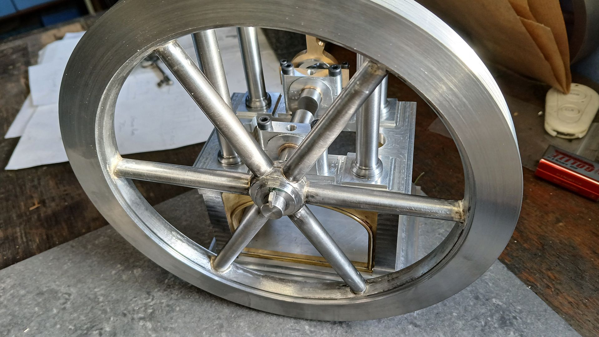
Vickers Inverted Engine
Vickers Inverted Engine
- This topic has 38 replies, 10 voices, and was last updated 27 February 2025 at 22:27 by
 Nigel Graham 2.


- Please log in to reply to this topic. Registering is free and easy using the links on the menu at the top of this page.
Latest Replies
-
- Topic
- Voices
- Last Post
-
-
J & S grinder – electrics
Started by:
gerry madden
in: Manual machine tools
- 4
-
22 April 2025 at 22:59
Chris Crew
-
Geography lesson required?
Started by:
duncan webster 1
in: The Tea Room
- 4
-
22 April 2025 at 22:50
Nealeb
-
50,000 Ton Press
Started by:
Vic
in: The Tea Room
- 7
-
22 April 2025 at 22:36
Vic
-
Building Bernard Tekippe’s Precision Regulator
1
2
Started by:
Chris Raynerd 2
in: Clocks and Scientific Instruments
- 10
-
22 April 2025 at 22:20
Chris Raynerd 2
-
Model Turbines
1
2
…
23
24
Started by:
Turbine Guy
in: Stationary engines
- 28
-
22 April 2025 at 21:59
Turbine Guy
-
Crossley four stroke engine.
Started by:
Grizzly bear
in: The Tea Room
- 2
-
22 April 2025 at 21:09
Bill Phinn
-
First 3D metal Printed Part
Started by:
JasonB
in: 3D Printers and 3D Printing
- 13
-
22 April 2025 at 20:57
Bill Phinn
-
Warco WM12 “flex”
Started by:
michaeljf93
in: Beginners questions
- 11
-
22 April 2025 at 20:51
KEITH BEAUMONT
-
Solar panel lighting problem
Started by:
KEITH BEAUMONT
in: Electronics in the Workshop
- 6
-
22 April 2025 at 20:47
KEITH BEAUMONT
-
UPVC Exterior door slamming
Started by:
Glyn Davies
in: The Tea Room
- 11
-
22 April 2025 at 20:31
Keith Petley
-
Reeves acquires Hemingway Tools?
Started by:
derek hall 1
in: The Tea Room
- 2
-
22 April 2025 at 19:50
Roderick Jenkins
-
Gas Engine Needle Valve
Started by:
Chris V
in: General Questions
- 5
-
22 April 2025 at 19:34
Rick Hann
-
VFD Article in May issue 351
1
2
Started by:
Robert Atkinson 2
in: Model Engineer & Workshop
- 12
-
22 April 2025 at 19:29
Emgee
-
Generator size for vfd controlled 3 phase 5.5 kw motor
1
2
Started by:
PutneyChap
in: Electronics in the Workshop
- 12
-
22 April 2025 at 19:13
Stuart Smith 5
-
What Did You Do Today 2025
1
2
3
4
Started by:
JasonB
in: The Tea Room
- 26
-
22 April 2025 at 17:01
Pete.
-
Stopping milling chips going everyehere
1
2
Started by:
petro1head
in: General Questions
- 22
-
22 April 2025 at 16:50
Andrew Crow
-
Crewe model locomotive engineer.
Started by:
dave22
in: General Questions
- 1
-
22 April 2025 at 11:09
dave22
-
Clarify some plain bearing engineering principles please.
Started by:
samuel heywood
in: General Questions
- 13
-
22 April 2025 at 11:06
Nicholas Farr
-
Power tapping on the sx2p??
Started by:
samuel heywood
in: Manual machine tools
- 4
-
22 April 2025 at 09:45
Howi
-
Hello from Sussex
Started by:
renardiere7
in: Introduce Yourself – New members start here!
- 3
-
21 April 2025 at 22:14
renardiere7
-
Motor to lead screw coupling method
1
2
Started by:
nevillet
in: CNC machines, Home builds, Conversions, ELS, automation, software, etc tools
- 17
-
21 April 2025 at 21:15
John Haine
-
One for the electronics enthusiasts?
1
2
Started by:
An Other
in: The Tea Room
- 11
-
21 April 2025 at 17:25
An Other
-
Gear design
Started by:
John Haine
in: CAD – Technical drawing & design
- 5
-
21 April 2025 at 07:53
jacques maurel
-
Lercanidipine
Started by:
Michael Gilligan
in: The Tea Room
- 5
-
20 April 2025 at 21:25
JohnF
-
Stuart Twin Victoria (Princess Royal) Mill Engine
1
2
…
49
50
Started by:
Dr_GMJN
in: Work In Progress and completed items
- 32
-
20 April 2025 at 15:26
Dr_GMJN
-
J & S grinder – electrics


