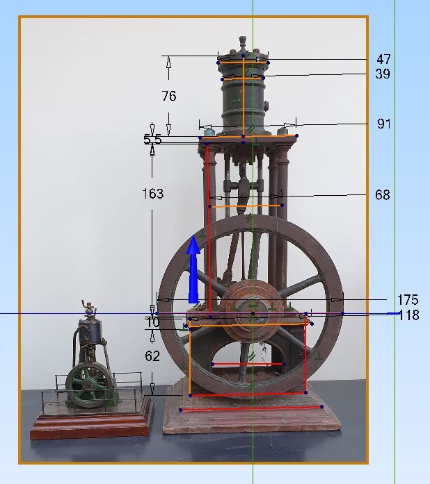
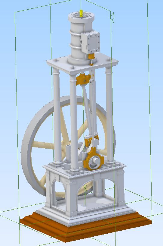
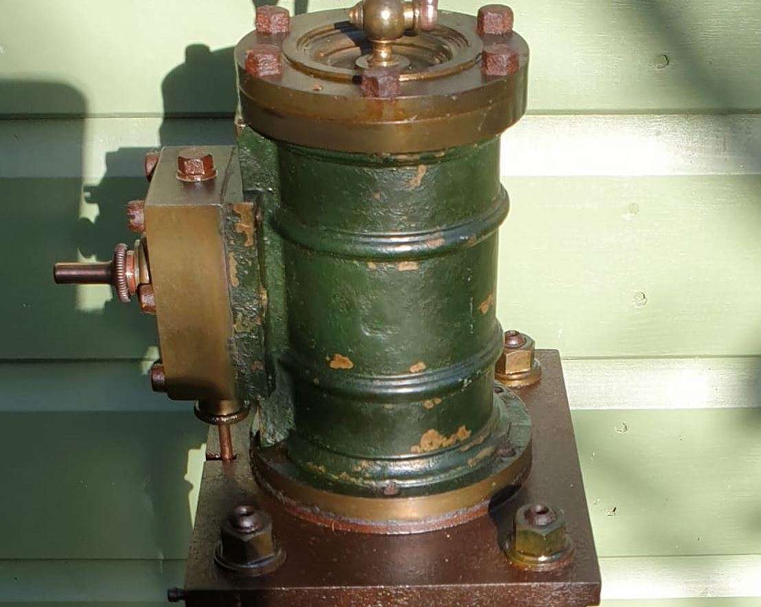
Vickers Inverted Engine
Vickers Inverted Engine
- This topic has 38 replies, 10 voices, and was last updated 27 February 2025 at 22:27 by
 Nigel Graham 2.


- Please log in to reply to this topic. Registering is free and easy using the links on the menu at the top of this page.
Latest Replies
-
- Topic
- Voices
- Last Post
-
-
Building Bernard Tekippe’s Precision Regulator
1
2
Started by:
Chris Raynerd 2
in: Clocks and Scientific Instruments
- 10
-
24 April 2025 at 23:53
Chris Raynerd 2
-
Broken casting – Best repair?
Started by:
John McCulla
in: Workshop Techniques
- 3
-
24 April 2025 at 23:21
noel shelley
-
Motor bearings and more
Started by:
Sonic Escape
in: General Questions
- 7
-
24 April 2025 at 22:58
halfnut
-
Tensile Strength Machineability
Started by:
kevian64
in: Beginners questions
- 8
-
24 April 2025 at 22:34
Huub
-
3D printer choices
Started by:
Matt Harrington
in: 3D Printers and 3D Printing
- 11
-
24 April 2025 at 22:07
Michael Gilligan
-
What Did You Do Today 2025
1
2
3
4
Started by:
JasonB
in: The Tea Room
- 26
-
24 April 2025 at 22:04
Sonic Escape
-
Power hacksaw – powerful banging when running
Started by:
ell81
in: Beginners questions
- 2
-
24 April 2025 at 21:03
Bazyle
-
1920s Cradle Mic Antique Brass Sleeve
Started by:
paulc1
in: Help and Assistance! (Offered or Wanted)
- 2
-
24 April 2025 at 20:51
JasonB
-
Low Current Power Bank
Started by:
Alan Wood 4
in: Electronics in the Workshop
- 4
-
24 April 2025 at 19:51
Michael Gilligan
-
Amolco Mill.
Started by:
Lee Rogers
in: Manual machine tools
- 5
-
24 April 2025 at 19:24
Michael Gilligan
-
Warco WM12 “flex”
Started by:
michaeljf93
in: Beginners questions
- 12
-
24 April 2025 at 17:38
Pete
-
Arduino controlled stepper motor for Mill X-axis drive
1
2
Started by:
nevillet
in: CNC machines, Home builds, Conversions, ELS, automation, software, etc tools
- 12
-
24 April 2025 at 17:30
John Haine
-
Confusing motor connections – 240v motor
Started by:
ell81
in: Beginners questions
- 5
-
24 April 2025 at 16:58
noel shelley
-
Hello from Sunny Skegness
Started by:
kevian64
in: Introduce Yourself – New members start here!
- 6
-
24 April 2025 at 16:15
SillyOldDuffer
-
RequiredOutside Diameter to Cut 5/16 BSF Thread
1
2
3
Started by:
James Alford
in: Beginners questions
- 24
-
24 April 2025 at 16:10
Danni Burns
-
Parkside Electronics
Started by:
Clive Steer
in: General Questions
- 6
-
24 April 2025 at 14:53
mjbarratt
-
50,000 Ton Press
Started by:
Vic
in: The Tea Room
- 12
-
24 April 2025 at 13:58
halfnut
-
CNC Coolant
Started by:
Steve355
in: CNC machines, Home builds, Conversions, ELS, automation, software, etc tools
- 7
-
24 April 2025 at 13:14
Dave S
-
lifting, levelling and wheeling around a lathe
Started by:
beeza650
in: Beginners questions
- 12
-
24 April 2025 at 12:43
halfnut
-
Gas Engine Needle Valve
Started by:
Chris V
in: General Questions
- 7
-
24 April 2025 at 09:27
Neil Lickfold
-
original benz
Started by:
tom hardy
in: General Questions
- 2
-
24 April 2025 at 09:12
JasonB
-
First 3D metal Printed Part
Started by:
JasonB
in: 3D Printers and 3D Printing
- 14
-
24 April 2025 at 07:28
Adrian Johnstone
-
VFD Article in May issue 351
1
2
Started by:
Robert Atkinson 2
in: Model Engineer & Workshop
- 12
-
23 April 2025 at 20:49
Robert Atkinson 2
-
Lady Stephanie
Started by:
Steve Huckins
in: General Questions
- 4
-
23 April 2025 at 20:38
alan ord 2
-
Tools scam on Facebook
Started by:
Bazyle
in: General Questions
- 1
-
23 April 2025 at 19:37
Bazyle
-
Building Bernard Tekippe’s Precision Regulator
1
2
Latest Issue

Newsletter Sign-up
Latest Replies

