Vice design question

Advert

Vice design question

Home Forums Beginners questions Vice design question

Viewing 15 posts - 1 through 15 (of 15 total)
  • Author
    Posts
  • #9458
    Robin Graham
    Participant
      @robingraham42208
      Advert
      #387507
      Robin Graham
      Participant
        @robingraham42208

        Possibly not the best time to ask as folk will be busy putting Santa's mince pies & whisky out, and reinforcing their stockings to withstand the burden of heavy cast iron gifts, but…

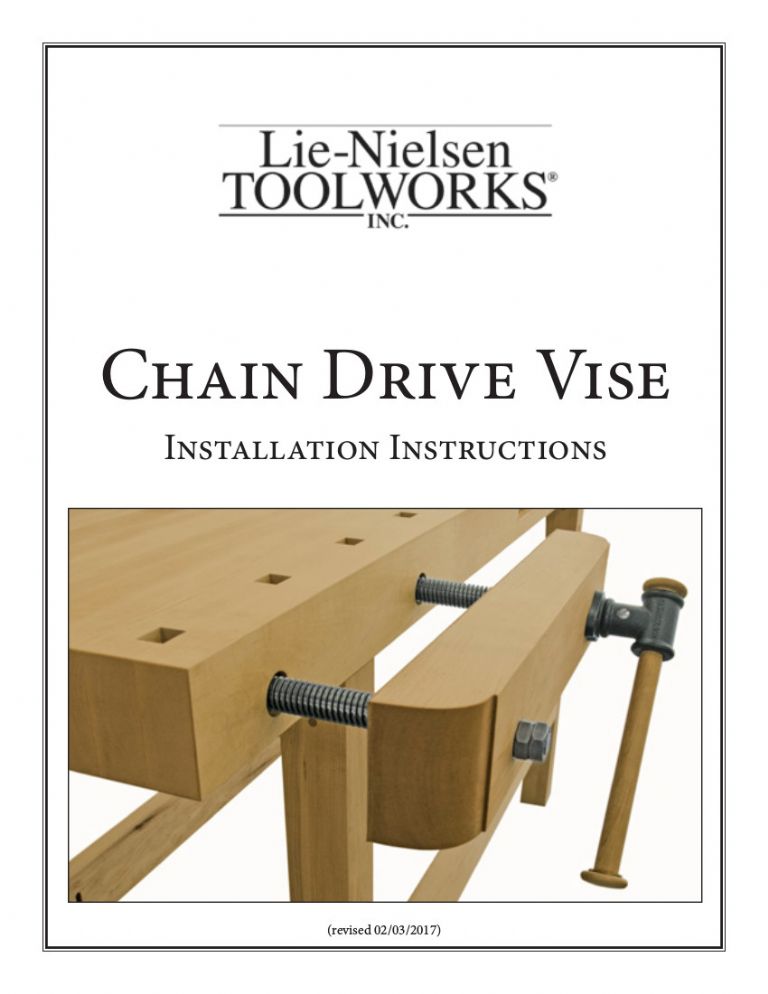
        A couple of weeks ago I posted about a DIY woodworking vice – I got involved in doing some metalwork for the thing – this gives an idea of the design.

        lnviceassembled.jpg

        The metalwork went OK, but the vice is stiff to work. I'd assumed that the design was OK as Lie Nielsen is pretty high-end. I now think it may not be such a great idea. Looking at the various screw driven devices I have in my workshop (vices, milling table, lathe slides) I realise that the screw exists only to exert an axial force. There is always some support for the moving part so the screw doesn't suffer any bending force. For example my ancient Record woodworking vice has two substantial (one inch) bars supporting the moving jaw and there is no sideways force on the screw. So I'm now doubting the wisdom of giving the screws the double duty of supporting the moving jaw (which weighs maybe 7kg with the metalwork) and moving it. Seems to me that's always going lead to the screw binding to some extent.

        I don't know – just canvassing opinion from those more experienced than me.

        Merry Xmas to all, Robin

        #387509
        John Reese
        Participant
          @johnreese12848

          Clamping forces in woodworking vises are quite a bit lower than in metalworking vises. The screws used in that woodworking vise are rather large. If they are properly guided below the bench top I would expect them to perform well.

          #387512
          Michael Gilligan
          Participant
            @michaelgilligan61133
            Posted by John Reese on 24/12/2018 23:52:28:

            Clamping forces in woodworking vises are quite a bit lower than in metalworking vises. The screws used in that woodworking vise are rather large. If they are properly guided below the bench top I would expect them to perform well.

            .

            Fair comment, John … 'though I am struggling to understand what you mean by 'properly guided below the bench top' if it's not the additional bars that Robin craves.

            It's probably bedtime

            MichaelG.

            #387525
            JasonB
            Moderator
              @jasonb

              May be worth looking at the install details to get an idea of what is going on.

              The screws run in a pair of guides, the front of which is a couple of inches back from the front of the bench.

              Most of the wooden jawed vices have screws around this sort of size, mostly to get a coarse pitch so you don't spend all day winding the handle, my own Sjobergs has similar size though just single screw with rods either side.

              Edited By JasonB on 25/12/2018 08:11:55

              #387527
              Michael Gilligan
              Participant
                @michaelgilligan61133
                Posted by JasonB on 25/12/2018 07:13:44:

                May be worth looking at the install details to get an idea of what is going on.

                .

                Thanks, Jason yes

                It is a little better than I had feared.

                MichaelG.

                .

                Mind you … This did rather surprise me:

                "Chain Drive Vise Installation Time:  Up to 12 hours (including making your own Vise Jaw and Bench prep.)


                Edited By Michael Gilligan on 25/12/2018 08:04:39

                #387531
                JasonB
                Moderator
                  @jasonb

                  I think the problem of trying to support it with rods is that they would need to be quite close fitting which then gives problems of clogging up and as the bench moves over the seasons it could just lock up. Single screw vices do have a pair of rods but there is quite a bit of play in them and the nut.

                  Also where to put the rods, can't really go outside the screws as you are getting close to the end of the moving jaw and it will restrict the gripping area of any work held at the end. Put them inside of the screws and you loose the whole reason for fitting a twin screw which is that they allow boards to be stood vertically in the gap between the screws.

                  Edited By JasonB on 25/12/2018 07:59:15

                  #387534
                  Michael Gilligan
                  Participant
                    @michaelgilligan61133
                    Posted by JasonB on 25/12/2018 07:58:33:

                    … Also where to put the rods, can't really go outside the screws as you are getting close to the end of the moving jaw and it will restrict the gripping area of any work held at the end. Put them inside of the screws and you loose the whole reason for fitting a twin screw which is that they allow boards to be stood vertically in the gap between the screws.

                    .

                    I suppose the best place would be above, or below, each screw

                    [ making things even bigger, more complicated, and costly ]

                    … an interesting 'puzzle' for Christmas

                    MichaelG.

                    #387550
                    Clive Foster
                    Participant
                      @clivefoster55965

                      These chain drive vices seem to be a fundamentally iffy concept. I understand that the idea is to get more evenly distributed clamping on a long workpiece than can be achieved with a single screw. But, as Jason says, woodworking vices need to operate with relatively large clearances which inevitably compromise the jaw guiding accuracy required if a twin screw system is to deliver even clamping. We won't mention chain slack effects.

                      Both the Lie-Nielson and similar Veritas types **LINK** use a close coupled Acme screw thread to provide both guidance and movement with no extra bearings surfaces. The Veritas looks marginally better engineered as the nut is solidly supported with fixed flanges screwed direct to the bench whilst the Lie-Nielson nut carriers have a bit of float. Probably irrelevant really as no woodworker is going to achieve engineering standards of accuracy. And even if they did wood moves with environmental changes so accuracy will soon be lost.

                      Seems to me that a more appropriate way of arranging the mechanics would be to put the threads and nuts at the back of the bench with a long plain shaft running out to the jaws through a pair of decently spaced support bearings. A foot or more between support bearings sounds good. Even a floppy woodworker friendly fits the support bearings ought to pretty much isolate the screw from bending movement in the nut. Should all work a lot easier. Making the rear support as a long tube with the nut at the back so the screw goes into it as it unwinds would give most support. Dunno why they don't make them that way as a long pre-made assembly incorporating shaft, screw and nut with appropriate fixing holes to screw under the bench would be much easier for woodworker types to install.

                      Clive.

                      PS Engineering comments.

                      Engineering wise the whole Lie-Nielson and Veritas concept doesn't even make it to flawed. If you are going to use a screw as a bearing correct practice is to employ a recirculating ball nut. Which would take the price right out of "How Much!!" territory into serious heart attack region. The tapered sides of an Acme thread mean that any sort of angular misalignment puts it into a continual slip-stick movement regain involving two large areas of tapered wedge working against each other. Objectively a square thread would be better as contact when misaligned by the load is mostly restricted to the corners. High forces but small area so probably easier to move. If the radial clearance is sensibly small I image that a square thread set-up would eventually wear so as to give good contact on the top and bottom faces of the thread without too much out of alignment contact between the thread sides. Which might actually work pretty well. Never happen with a normal Acme system as the book radial clearances are too large. I wonder if the hot moulded Derin system used by many home shop workers to make accurate half nuts would work well here as you get nominal zero radial clearance. Square thread probably still better tho'.

                      Clive would probably make a hydraulic system as being a much more interesting challenge.

                      Edited By Clive Foster on 25/12/2018 09:43:31

                      Edited By Clive Foster on 25/12/2018 09:44:14

                      Edited By Clive Foster on 25/12/2018 09:45:05

                      Edited By Clive Foster on 25/12/2018 09:46:11

                      #387583
                      Jeff Dayman
                      Participant
                        @jeffdayman43397

                        I agree with Clive that doing a chain drive mechanism in the jaw is a fundamentally flawed method for several reasons. Taking his points further, if twin vise operating devices are a must, why not use plain rods mounted in the vise, traveling back through round acetal or bronze bearings in the bench, to operate the jaw. At the rear of the rods under the bench, connect them with an equalizer bar as used on locomotive brakes. Dead centre to the bar, take a forked end threaded rod back to a mounted single nut. The mechanism to turn the nut for tightening could be taken off in several directions several ways with gears or chain or universal joints out to handles or sockets for cranks etc.

                        A single screw in centre of the Lie Nielsen vise could be used with a simple wedge in the open end to hold work vertically beside the screw and would balance the force on the vise jaw. This would still give a wide jaw open for long work to the floor, and it would be easier to load work beside a screw rather than between two screws.

                        The Lie Nielsen and the Veritas stuff are reassuringly expensive, and are carefully marketed to the target audience of affluent older workers of the brown stuff. These brands are not a guarantee of good design or great usability.

                        Just my $0.02 worth. Your mileage may vary.

                        Edited By Jeff Dayman on 25/12/2018 16:33:50

                        Edited By Jeff Dayman on 25/12/2018 16:35:00

                        Edited By Jeff Dayman on 25/12/2018 16:36:16

                        #387584
                        Michael Gilligan
                        Participant
                          @michaelgilligan61133

                          I think I would retain the double action, but separate guidance from clamping

                          Imagine a pair of drawer sides with sliding-bearing surfaces [PTFE against Formica ?] at top, bottom, and the outer face. Then a pair of screws, one inboard of each inner face.

                          The screws could be smaller diameter than Lie-Neilson uses, because they are now only clamping.

                          The chain would be replaced by a timing belt [or perhaps use a pair of synchronised stepper motors on the de-luxe model ? … or, of course, Clive's Hydraulic system]

                          .

                          Just a bit of mental doodling … it's never likely to happen, because I have no space for such a bench.

                          MichaelG.

                          #387646
                          Clive Foster
                          Participant
                            @clivefoster55965

                            Hafta confess that my suggestion of hydraulic operation was made somewhat tongue in cheek, or mental doodling as MichaelG would say.

                            However in the cold light of dawn I'm beginning to wonder if it might actually be practical at a viable price for a saleable product.

                            Consider two long, smooth finished and suitably sturdy tubes running in a set of bearing bushes carried by a support structure under the bench. I imagine something around 1 1/2" diameter by 1/8' wall counts as suitably sturdy tube. U section aluminium extrusion looks good for the support structure with three or four solid square plastic bushes for the tube to run in fixed at appropriate intervals. Neatest way is to use a reversed type hydraulic cylinder, powered on the contraction stroke, fixed inside each tube to drive it. Usual oil feed, extra seals and bleeding issues as compared to the simple extending type but nothing insurmountable. I imagine such cylinders can be sourced at reasonable prices from China Inc.

                            Ordinary extending type cylinder driving from the front via the support structure would work fine but thats messy engineering and drive is inevitably offset. Easiest way for DIY guy to go. Especially if one cylinder would do. Slim sleek integrated look with clean modern lines ought to be worth £££ on the selling price of a commercial product!

                            If suitable seals can be sourced inexpensively its practical to integrate the hydraulics into the main tube with a solid stop to separate the hydraulic section from the pure support part. Oil feed has to be down a hollow piston rod so the bleed, equalisation orifices and pump connections come nicely out of the way at the back of the bench. I imagine suitably well finished tube is made by the Chinese mile for gas ram and similar duties so should be obtainable at reasonable prices. Need reasonable numbers if the cost isn't to be too high.

                            Vice opening needs a spring or gas ram operating via the support structure. Simple two pedal drive unit on the floor with pump on one pedal, release on the other. Need a tie bar across the ends of the tubes, more U section extrusion, to keep things properly aligned. Vice jaw would have to be slackly mounted to get the minor floppiness essential to a woodworkers vice.

                            Hands free operation would be a major selling point as would smooth static tubes to rest the work on rather than the screw threads of the chain drive systems which will tend to mark the work. A big no-no if doing a quality job. Supply as two units with the cylinders / support tube pre-assembled into the channel section supports. Cross ties provided in "cut to length" form for vice jaw and under bench support spacing. Pre-drilled for a selection of vice jaw lengths of course.

                            Big disadvantage from supplier viewpoint is less than sky-high profit margin. Chain drive design looks to have under £50 of hardware at Ali-Baba prices. How much does it cost to have it all put in a box? I guess the semi steam-punk look may have marketing advantages too.

                            If you had to stay with chain and screw drive longer shafts with screws at the back gains most of the advantages but vice jaw has to be stiffly located on the shafts if the chain drive is to function well. So outside end support bushes need to be sloppy. Inevitably still some movement and binding tendencies getting back to the screw. proper way is a UJ between screw and outer shaft but now the screw needs its own supports. Which takes the whole design out of the marketing price point. I imagine Jeffs single screw and equaliser concept could come out surprisingly expensive too due to needing a number of design specific parts. Almost everything in the commercial chain drive systems comes out of the mass production standard parts bins.

                            Clive.

                            Edited By Clive Foster on 26/12/2018 10:15:51

                            #387655
                            Brian G
                            Participant
                              @briang

                              I don't see a problem with the use of the screws to align the vice, it evidently works well on conventional dual screw vices. What bothers me is the near impossibility of getting equal clamping pressure at both ends of a large workpiece. Almost certainly one screw will tighten more than the other. Perhaps the simplest answer (other than ditching the chain and fitting dual handwheels like most other dual screw vices) is to give the vice a floating face, pivoted at the centre. This could be a separate timber component, dropped in when needed.

                              Brian

                              #387670
                              Neil Wyatt
                              Moderator
                                @neilwyatt

                                The original patent (linked in the old thread) was to improve the old vertical leg-vices that always closed at an angle.

                                Neil

                                #387754
                                Robin Graham
                                Participant
                                  @robingraham42208

                                  Thanks for replies, tongue in cheek and otherwise – oddly enough the guy I'm working with on this let slip that his next project was a motor driven vice, which will be even more exciting!

                                  I realise that I might be tilting at windmills here, but having no formal background in engineering (or woodwork) I sometimes take on jobs outside my comfort zone for free just to learn new stuff. Unlike the guy who changed the clutch plates on my Citroen C5 (not done one of these before mate, took me 10 hours, so with parts that's erm, 600 quid). Sorry, an aside, but still hurting!

                                   It's been an interesting discussion for me at least  but I still think it's a flawed design (thanks Clive for your detailed explanation of the stresses on the threads) , although as Neil points out the original idea was to improve on the non-parallel leg vices which it probably does. In this case the problems are exacerbated because the DIY blocks (not of my making) which hold the nuts (they are called standoffs in the the instructions which JasonB linked to)- have a lot of float, and the finish on the screws is a bit badger's, which doesn't help either. Total cost of the hardware so far is £25 against LN price of 285 USD, so we have something in the budget for experimentation!

                                  Personally I can't see the need for this vice in a hobby workshop, there's always a workaround with clamps and whatnot, but hey-ho, all part of life's rich tapestry

                                  I'll let y'all know know it goes , Robin.

                                  PS if the design of this site allowed multiple quotes I'd have made more detailed and individual replies to the points raised – but life is too short for cutting and pasting. My thanks to all of you who have contributed though.

                                  R

                                  Edited By Robin Graham on 27/12/2018 00:42:14

                                  Edited By Robin Graham on 27/12/2018 00:43:20

                                  Edited By Robin Graham on 27/12/2018 00:44:05

                                  Edited By Robin Graham on 27/12/2018 00:45:14

                                Viewing 15 posts - 1 through 15 (of 15 total)
                                • Please log in to reply to this topic. Registering is free and easy using the links on the menu at the top of this page.

                                Advert

                                Latest Replies

                                Home Forums Beginners questions Topics

                                Viewing 25 topics - 1 through 25 (of 25 total)
                                Viewing 25 topics - 1 through 25 (of 25 total)

                                View full reply list.

                                Advert

                                Newsletter Sign-up