Vibration and exploring the Fast Fourier Transform with CAD
Vibration and exploring the Fast Fourier Transform with CAD
Home › Forums › CAD – Technical drawing & design › Vibration and exploring the Fast Fourier Transform with CAD
- This topic has 54 replies, 12 voices, and was last updated 13 March 2025 at 11:33 by
 Julie Ann.
-
AuthorPosts
-
7 March 2025 at 08:49 #787574
SillyOldDuffer
Moderator@sillyolddufferAnother issue, perhaps the mathematicians can help? My maths limit is at the Complex Number / Calculus level. I know what a complex number is, and why they are useful, but am hazy about applying them. (Broadly, a complex number has a real part and an imaginary part, very helpful when calculating rotating problems, like vibrations, if you understand it.) In this example I told GNU RC to work with floats, seems OK, but doing so must lose information, which might cause trouble later. As unnecessary guessing isn’t engineering can anyone explain when it’s OK to model in floats and when complex numbers become vital? Please be gentle, I’m out of my depth!
…
I’m not sure I understand the question regarding floats? I would take a float to mean floating point, ie, mantissa and exponent, as opposed to an integer. It’s about arithmetic representation, not whether the number is real or complex. A complex number consists of two real numbers, however they are represented in the computer.
…Julie
Jargon mismatch I think! My background is Software Engineering, where float is shorthand for floating point, in various precisions. As I’m using a modern computer, my floats are 64 bit (and the built-in maths co-processor is almost certainly 80bit IEEE extended.)
floats manipulate single numbers, so 3.142 X 2 = 6.284 We’re all familiar with that.
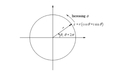
complex numbers consist of two floats, real and imaginary, meaningful as a pair, and operations (+,-, * sqrt() etc) obey different rules. Useful when calculating frequencies, where a sine wave is generated by the position of a point rotating around the origin at an angular velocity:

The position of the point is represented by two numbers, not one.
So my question is, in what circumstances does FFT require a complex input, and when is it OK to feed it floats. I guess floats imply a rotation, a convention like 60 floats per rotation, whereas complex numbers provide complete information. Points on the wave are fully identified.
Hospital appointment. Must go.
Dave
7 March 2025 at 09:11 #787576 Michael GilliganParticipant@michaelgilligan61133
A very useful free download:
MichaelG.
.
A weighty tome, but it added nowt to the iPad’s portability 🙂
7 March 2025 at 12:22 #787596 Julie AnnParticipant@julieann
It seems that there is a misunderstanding of the Fourier transform and complex numbers, and the difference between the theory and implementation.
As an aside I prefer to say 2-dimensional numbers rather than complex, as I don’t see them as complex. If 2-dimensional numbers are complex what do you call 4-dimensional numbers (quaternions) or 8-dimensional numbers (octonions)? But I’ll stick with saying complex as it is quicker to type! Complex numbers follow the normal rules of arithmetic in that they are associative and commutative in both addition and multiplication.
The question of when to input real or complex numbers to the FFT makes no mathematical sense. The Fourier transform is inherently complex. So the input and output sequences are always complex. If a series of real numbers are input the Fourier transform still treats them as complex, it is just that the imaginary part is zero. Similarly the output of a Fourier transform is inherently complex. It also makes no difference as to how the numbers are represented within the computer as long as it is consistent. So the question about floats, or not, doesn’t make sense?
As mentioned earlier there are some specific cases where properties of the input sequence (real/complex or odd/even) result in output sequences with specific properties.
In the electrical world representation of a complex number in terms of magnitude and phase is often more useful when looking at results.
It seems that the software used by SoD is rather quirky in its definitions. I recently attended a couple of lectures organised by Cambridge University Amateur Radio Club on the software, and underlying mathematics, of a SDR software package. The maths was simple enough but the implementation was distinctly odd. In my world sinks are in the kitchen not software packages!
Julie
7 March 2025 at 13:18 #787601SillyOldDuffer
Moderator@sillyolddufferIt seems that there is a misunderstanding of the Fourier transform and complex numbers, and the difference between the theory and implementation.
Very likely! And why I started the post. So Julie’s comments are most welcome.
As an aside I prefer to say 2-dimensional numbers rather than complex, as I don’t see them as complex. If 2-dimensional numbers are complex what do you call 4-dimensional numbers (quaternions) or 8-dimensional numbers (octonions)? But I’ll stick with saying complex as it is quicker to type!
Agreed, though all my admittedly ancient maths text books call them complex numbers. I know 4-dimensional numbers are quaternions, having struggled with them to combine the outputs of a MEMS sensor. (3D axis outputs from each of a gyroscope, accelerometer and magnetometer.) Really difficult. Fortunately this project only needs floats and maybe complex.
Complex numbers follow the normal rules of arithmetic in that they are associative and commutative in both addition and multiplication.
Not quite complete? How about the square root of a complex number? This is where my poor old bonehead goes pop!
The question of when to input real or complex numbers to the FFT makes no mathematical sense. The Fourier transform is inherently complex. So the input and output sequences are always complex. If a series of real numbers are input the Fourier transform still treats them as complex, it is just that the imaginary part is zero.
Excellent, I’ve got it. But what is the consequence of the imaginary part being zero? To my mind information is lost. If FFT works without needing a complex input, then why do most FFT algorithms take it? I’m guessing the answer is horses for courses: floats are fine for what I’ve done so far, but other applications might demand a complex number stream.
Similarly the output of a Fourier transform is inherently complex. It also makes no difference as to how the numbers are represented within the computer as long as it is consistent. So the question about floats, or not, doesn’t make sense?
It does from the point of view of a garbage in garbage out trained programmer. As a float isn’t a complex number, I perceive that the input to the FFT Block is incomplete, and because the imaginary component is missing, the FFT algorithm might be compromised in some way.
As mentioned earlier there are some specific cases where properties of the input sequence (real/complex or odd/even) result in output sequences with specific properties.
In the electrical world representation of a complex number in terms of magnitude and phase is often more useful when looking at results.
Useful again thanks.
It seems that the software used by SoD is rather quirky in its definitions.
Could be, though it seems fairly consistent with other sources I’ve looked at. Mostly SDR but also other applications. Could be a coincidence, I’m not widely read.
I recently attended a couple of lectures organised by Cambridge University Amateur Radio Club on the software, and underlying mathematics, of a SDR software package. The maths was simple enough but the implementation was distinctly odd.
I too have noticed implementations that seem odd, except I assumed it was because I didn’t understand them!
In my world sinks are in the kitchen not software packages!
Jargon again, sources and sinks are common in my experience.
Julie
One more question if I may. Julie explains the output of an FFT is fundamentally complex numbers. I visualise FFT as building a frequency count in the same was as a histogram. That is, an FFT algorithm set to 1024 points will count frequencies within the given bandwidth into the nearest bucket. If speed rather than resolution matters, the algorithm set to 128 buckets does a lot less computation. But if higher resolution is needed, the number of points (buckets) can be increased, the cost being far more number crunching. Whatever the resolution, the buckets can be graphed X and Y with floats, or with X & Y encoded into the real and imaginary parts of a complex number. Is that sensible, or am I howling at the moon?
Many thanks, most helpful.
Dave
7 March 2025 at 14:17 #787611SillyOldDuffer
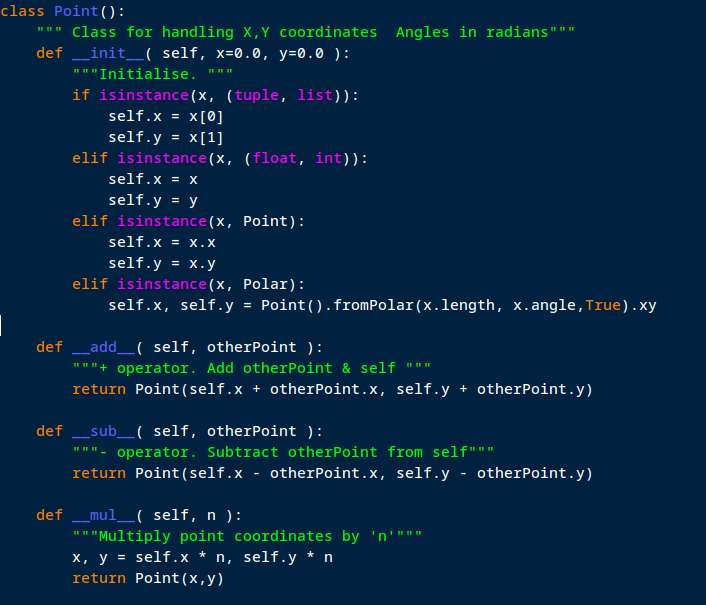
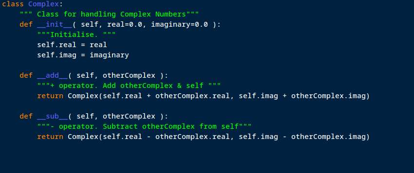
Moderator@sillyolddufferMight help to see how a computer language that supports classes might handle Complex Numbers and Points under the bonnet. A class is a user defined type, that can be added to extend the language and make the code easier to understand by hiding implementation details.
My point class was developed to support 2D graphical applications. X,Y coordinates are handled as a unit, and the class overloads the usual mathematical operators accordingly. This is a snippet showing new Points can be created from x,y, or a list, or another Point, or a Polar. The code needed to do +, – and * is shown.
Given the class has been defined, the programmer can write:
a = Point(100,200)
b = Point(200,333)c = a + b
Minus can be implemented to give distance between rather than another point. Either the straight-line distance as the crow flies or the Manhattan distance, which is the sum of distance along and up, when diagonal movement is forbidden. Both are valuable when computing cutter movements in a CNC system; moving the cutter the shortest distance is great unless it crashes into the job, in which case Manhattan can be used to steer around obstacles.

Complex numbers are rather similar to 2D Points, but the rules differ. This example shows similarities! Many differences as the class if developed. I don’t think it makes any sense to take the square root of a Point, but it is useful to compute the square root of a complex number. Including support for the square root of -1, which is a floating point error (NaN, Not a Number), but legal in Complex Number maths. Makes my head hurt!

GNU Radio Companion hides these details, so with luck they won’t get in the way. But once the modelling is over, I would have to code the design to run on a microcontroller, raspberryPi, or laptop. Mostly using libraries, not defining complex numbers myself, but I still have to understand complex numbers better. Are they needed at all at the build stage, and, if essential, exactly how are they applied? This is just like Mechanical Engineering CAD: having modelled an object, more work to actually make the physical object.
Dave
7 March 2025 at 14:43 #787615SillyOldDuffer
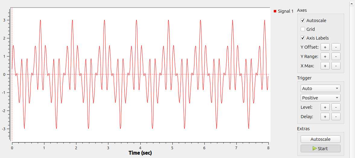
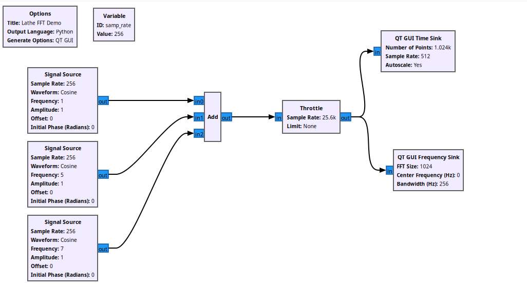
Moderator@sillyolddufferBack on topic, I’ve found that double-clicking on an Instrument Block opens a tabbed window. The config tab allows a Control section to be added, and this can be tweaked to improve the display when the defaults aren’t right. This gives a better time view of my 1Hz + 5Hz + 7Hz test mix:

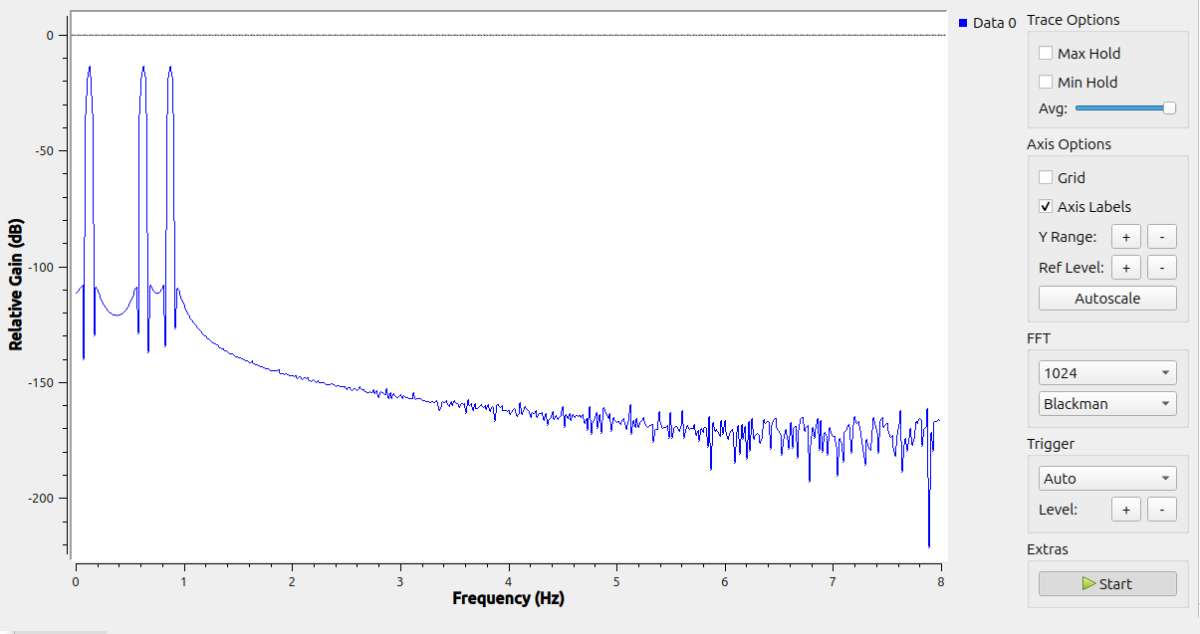
Reducing the sample rate down to 128 per second produces a clearer Frequency Domain. The example is displayed ‘Half Spectrum’:

The 1Hz, 5Hz and 7Hz spikes stand out. The x-axis scale is better, still wrong. More work!
The control panel lets me switch FFT windowing options on the fly. Now possible to see which one looks best, even if I don’t understand why yet.
Progress, not quite as foggy as when I started!
Dave
7 March 2025 at 18:05 #787619SillyOldDuffer
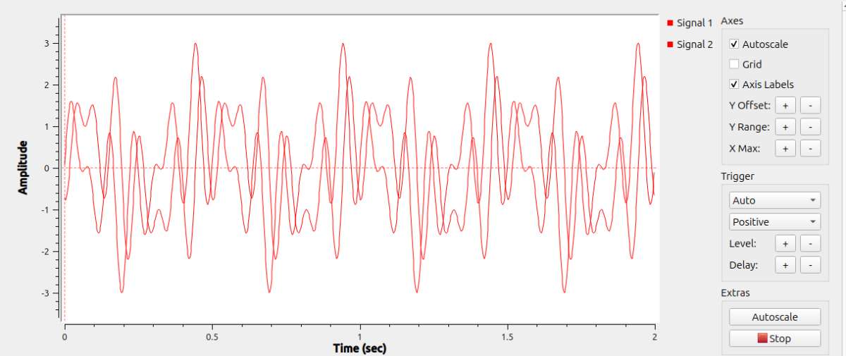
Moderator@sillyolddufferI altered the model to use Complex Numbers throughout:

Now the time display has two signals, presumably real and imaginary, and they’re a bit different. Hmmm.

The Frequency Domain scales correctly, and the peaks are at 1, 5 and 7Hz as expected. Oddly. the option to only graph positive results disappears when the input is a Complex Number stream, I don’t know why?
It appears that Complex Number and floating point streams are different, at least in GRC and in this model.
Not shown, I added a noise source to the Add block, and was pleased to see FFT pretty much ignores it. The test frequencies are detected loud and clear.
Feeling rather better and not full of painkillers, I’m going to risk firing up my lathe and turn some nasty welded steel pipe with a coarse carbide insert to maximise the aggro. I’ll record the noise with an MP-3 player laid on the bed and feed it into the model. Been about a year since the lathe was powered up, no doubt rusted solid and mice have eaten the electrics…
Dave
7 March 2025 at 19:45 #787630SillyOldDuffer
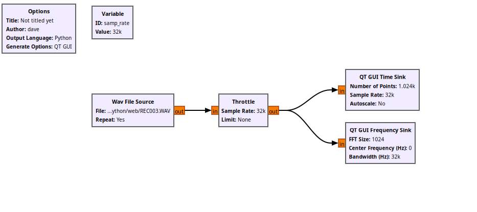
Moderator@sillyolddufferReturned from the workshop. As predicted the lathe didn’t power up cleanly! The fan that cools the VFD emitted a loud squeal, bearing problem, blades unstable maybe. Plenty of air moving, After howling for a few minutes it stopped, but I was able to record it.
The model:

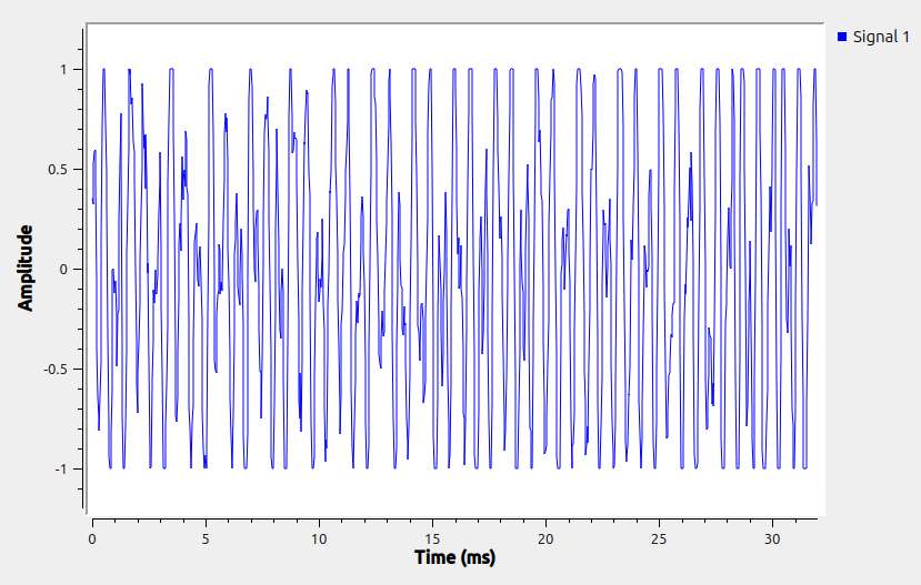
The squealing fan waveform:

TThe squeal frequencies are all dirty harmonics of 560Hz, the loudest being 1.68kHz. No need for a spectroscope, that it’s due to the VFD fan was bleeding obvious!
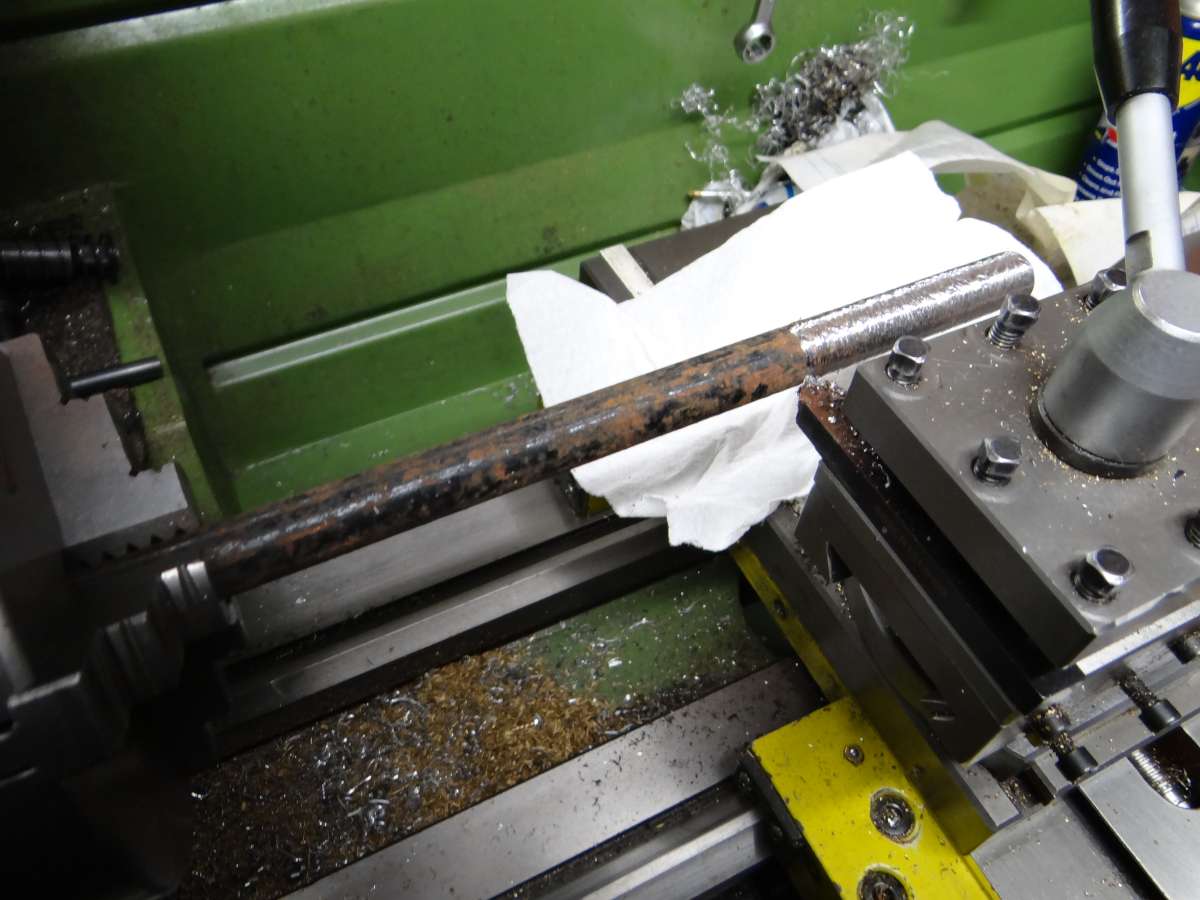
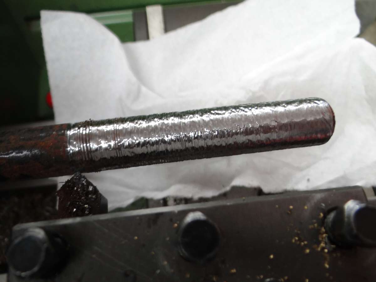
Next cutting metal, incompetently. 250mm of ⌀15mm welded gas pipe protruding unsupported from the chuck, and attacked with a blunt square insert, the saddle traversed jerkily by hand. Made a horrible noise.

Nigel thinks he has a banding problem, see this mess!

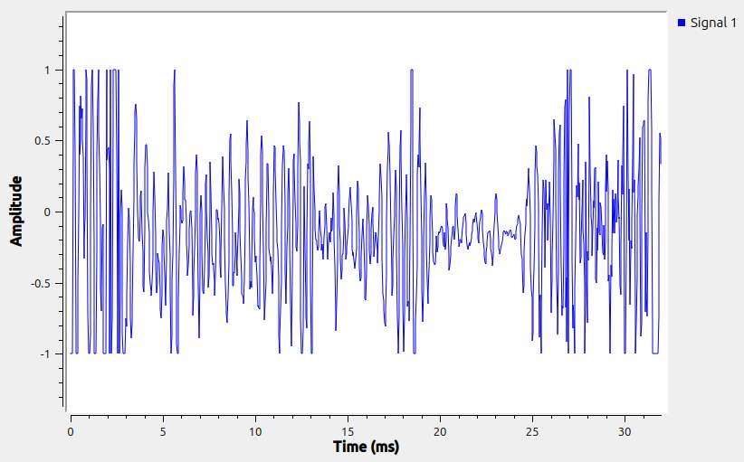
The waveform is messy too!

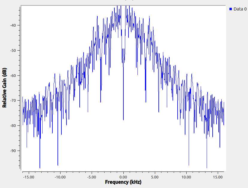
And the spectrogram shows dozens of frequencies. Too many to identify by hand, but can be done with a program.

Again, no need for electronics and software to identify root cause here, it was me torturing a lathe! But the example shows an ordinary microphone on an ordinary MP3 player successfully picks up audible vibrations. Have to think of a way of getting my lathe to vibrate at low frequencies to test if it can record them.
Promising.
Dave
7 March 2025 at 19:57 #787634John Haine
Participant@johnhaine32865Take square root of sum of squares of real and imaginary parts to get power from complex numbers.
7 March 2025 at 20:24 #787637 Michael GilliganParticipant@michaelgilligan61133[…] Have to think of a way of getting my lathe to vibrate at low frequencies to test if it can record them.
Your previously mentioned drive-belt ‘lumpiness’ would seem a reasonable source.
MichaelG.
7 March 2025 at 21:24 #787644garyash
Participant@garyashThere seems to be too much going on here (in the frequency analysis) to decipher it.
Thinking back a long time ago, at uni we did an experiment to show a half speed whirl of a shaft in an air bearing. To initiate the whirl the rotating shaft was tapped with a nylon faced hammer (which also started the recording of position). Perhaps you could replicate this so that there is only one input event and a less complex output. Changing speeds might tell you if the vibration is gear related.
In the air bearing experiment, the amplitude of the shaft disturbance was measured with a pair of perpendicular eddy current proximity sensors and increased either side of the critical speed with the orbiting shaft touching the bearing at the critical speed. Perhaps you could replace the microphone with a similar position sensor. Moving the sensor from the shaft to the tool (v the bed) could indicate if this is a tool (post, slides, etc) rigidity problem or something in rotating parts.
7 March 2025 at 22:00 #787650Nigel Graham 2
Participant@nigelgraham2No lathes were harmed in the making of this waveform…..
I leave the mathematics, programming and electronics to others; but will look at the practical measuring side.
The lower the frequency the more difficult it may be to obtain sensible results; and an audio microphone and its normal amplifier might not even be very effective.
If turning a bit of gash gas-pipe makes an ‘orrible noise an ordinary microphone and amplifier of reasonable quality will help you analyse that, but winkling out the effects of worn headstock bearings, gears etc. might be chasing vibrations of much larger amplitudes but which the sensor attenuates by its own frequency-response characteristics.
So I think you need decide what you are actually trying to analyse.
– Do you want a very broad band-width so you don’t miss very low frequency (vlf) vibrations that might show as surface-finish banding; perhaps from irregularities in the change-wheel and feed-shaft chain, a damaged gear or a lumpy belt?
– Are you after frequency peaks by frequency alone or do you want fair amplitude comparisons across the band as well? If the vlf vibration is severely attenuated by the sensor it could give a very misleading result.
If the latter you need then know the transducer’s voltage or charge response w.r.t frequency.
Note I have changed the term from microphone to “transducer”. For the latter includes the former but the former might not work very well at sub-audible frequencies.
A decent quality microphone ought have a fairly “flat” response over the human audible bandwidth – it might not match the ear because our ears do not have a flat response. (Even before we’ve knocked the top end off by too many rock gigs and gash gas-pipe machining.)
It’s going below perhaps 20Hz that the task becomes harder because generally microphones are designed for audio work, and machines can vibrate at almost any frequency. On the other hand the vibrations at 20kHz and above, on a conventional machine-tool of reasonable bulk, are likely to be harmonics and might not affect the machining quality anyway.
Below about 10 Hz the frequency-response of a small piezo-electric ceramic transducer, which a small microphone could be, is likely to diminish markedly; but this may be where the troublesome vibrations live. So for fair v.l.f. tests you still need a sensor with a flat frequency response descending to sub-Hertz response.
Indeed, a thorough assessment may need not only two or more sensors and their own appropriate amplifiers, but also knowing their voltage or charge responses w.r.t frequency, so you can compensate for them numerically. Hence going into acceleromater territory.
Now, some way back Robert suggested gluing a nut to the sensor element in a cheap “ear-bud”. I have never take one of those apart but I guess they are piezo-electric ‘speakers. If so he has made as I described above, a basic accelerometer: an active though not fully reciprocal element with a mass stuck to it.
By “reciprocal” I mean it will work as a microphone or loudspeaker, but… the frequency response will not be the same! They are designed to work in one direction, and are not very effective the other way.
I do not have any literature on vibration-measurements, only on noise measurements and that spans humanly-audible sound in air; not vibrations in solids and structures. Nor did I use accelerometers very often. So I have only basic general knowledge of piezo-electric accelerometers and equally importantly, their specific amplifiers that raise the transducer output to something the spectrum-analyser can analyse. Not the types suitable for v.l.f work.
However, I would still caution that what we might think “conventional” sensors might not be effective much below 20Hz.
…
A further point: the discussion so far is really on measuring two very different things.
Sound in air is a series of elastic vibrations to be sure, but the real point of the thread has been what we can consider as “sound” travelling through the material to become mechanical oscillation of the surface. That oscillation can only sensibly be detected by an accelerometer. The sound the vibrating surface might create in the air only tells us it is vibrating, and is no use for serious analysis of the material’s behaviour.
A microphone is made for air-acoustics and trying to use it as an accelerometer might give very skewed results, or simply not detect the vibrations you want to find.
By all means experiment, as Robert did, with making accelerometers; but do note that unless you can measure their transduction responses, the system will not show much more than frequency peaks, and those unfairly if the real problem vibrations are outside the transducer’s “flat” working band.
Note that an accelerometer has to be in intimate contact with the surface, otherwise much of the information is lost.
…
That parallel line of enquiry raises a second point.
Sound pressure levels in air and water are measured in deciBels referred to linear pressure units. The scale for airborne sound is:
so-many dB re[ferred to] 20µPa, meaning its 0dB equates to that pressure.*
(20 micro-Pascals: I am not sure if this forum’s text-editor will handle Greek characters.) The level is the absolute minimum the fully-healthy human ear can detect, the chosen standard because air acoustics in any numerical sense are relevant really only to humans. If you convert that 20µPa sweet-nothings level to Bar, what it tells you about your ears’ sensitivity is awe-inspiring indeed. Never mind litres-times-Bars. Marine acoustics sets its 0dB level at 1µPa, 26dB lower still.**
Vibrations in solids are by dB re 1g, where “g” is the standard acceleration due to gravity.
Since the transducer is changing the mechanical to electrical signals, the voltages for the calculations including amplifier gains, are in dB re 1V. Consequently the mathematics replace the linear-unit multiplications and divisions by additions and subtractions of logarithms.
…
* By S.P.L. = 20log [measured pressure / reference pressure] so
20log [20/20] = 20 log 1 = 0dB.
** By S.P.L. in water compared to that in air = 20log [1/20] = -26dB.
Logarithms to base-10.
8 March 2025 at 10:04 #787685SillyOldDuffer
Moderator@sillyolddufferNo lathes were harmed in the making of this waveform…..
…If turning a bit of gash gas-pipe makes an ‘orrible noise an ordinary microphone and amplifier of reasonable quality will help you analyse that, but winkling out the effects of worn headstock bearings, gears etc. might be chasing vibrations of much larger amplitudes but which the sensor attenuates by its own frequency-response characteristics.
So I think you need decide what you are actually trying to analyse.
Tut Nigel – have you read the topic? I do know what I’m trying to analyse. This is an experimental project, requiring a step-by-step exploration of a technology I don’t understand properly. Badly turning a gas-pipe is a only an example, not the goal. The point about detecting low-frequencies has already been raised and solutions suggested. That’s for later.
At the moment I’m concentrating on FFT, using synthesised waveforms rather than actual data. But I thought it interesting to see what an ordinary MP3 player could do in a simple 5 minute test: it’s not representative or complete, nor does it imply what I think a vibration analysing spectroscope should be good at.
Forgive the rant, I have tummy ache! But forum friends do have a tendency to take examples literally, missing the point that they are only illustrative, and jumping to assume they are real. I only use examples to illustrate – they’re design aids, explaining the thinking in general, not specific requirements. And to tail end topics without reading them properly!
– Do you want a very broad band-width so you don’t miss very low frequency (vlf) vibrations that might show as surface-finish banding; perhaps from irregularities in the change-wheel and feed-shaft chain, a damaged gear or a lumpy belt?
Yes, read the topic!
– Are you after frequency peaks by frequency alone or do you want fair amplitude comparisons across the band as well? If the vlf vibration is severely attenuated by the sensor it could give a very misleading result.
Yes, FFT does that, provided the sensor is suitable. At the moment I have done nothing with sensors, future work.
If the latter you need then know the transducer’s voltage or charge response w.r.t frequency.
Note I have changed the term from microphone to “transducer”. For the latter includes the former but the former might not work very well at sub-audible frequencies.
Agreed.
A decent quality microphone ought have a fairly “flat” response over the human audible bandwidth – it might not match the ear because our ears do not have a flat response. (Even before we’ve knocked the top end off by too many rock gigs and gash gas-pipe machining.)
Don’t care – I’m measuring vibration other than by ear.
It’s going below perhaps 20Hz that the task becomes harder because generally microphones are designed for audio work, and machines can vibrate at almost any frequency. On the other hand the vibrations at 20kHz and above, on a conventional machine-tool of reasonable bulk, are likely to be harmonics and might not affect the machining quality anyway.
Yes, as discussed already.
Below about 10 Hz the frequency-response of a small piezo-electric ceramic transducer, which a small microphone could be, is likely to diminish markedly; but this may be where the troublesome vibrations live. So for fair v.l.f. tests you still need a sensor with a flat frequency response descending to sub-Hertz response.
Yes, as discussed already.
Indeed, a thorough assessment may need not only two or more sensors and their own appropriate amplifiers, but also knowing their voltage or charge responses w.r.t frequency, so you can compensate for them numerically. Hence going into acceleromater territory.
Good idea! Not thought of that, ta.
Now, some way back Robert suggested gluing a nut to the sensor element in a cheap “ear-bud”. I have never take one of those apart but I guess they are piezo-electric ‘speakers. If so he has made as I described above, a basic accelerometer: an active though not fully reciprocal element with a mass stuck to it.
By “reciprocal” I mean it will work as a microphone or loudspeaker, but… the frequency response will not be the same! They are designed to work in one direction, and are not very effective the other way.
Agreed, but I don’t care – I’m only interested in detecting and measuring vibrations, not playing them back audibly.
I do not have any literature on vibration-measurements, only on noise measurements and that spans humanly-audible sound in air; not vibrations in solids and structures. Nor did I use accelerometers very often. So I have only basic general knowledge of piezo-electric accelerometers and equally importantly, their specific amplifiers that raise the transducer output to something the spectrum-analyser can analyse. Not the types suitable for v.l.f work.
However, I would still caution that what we might think “conventional” sensors might not be effective much below 20Hz.
No need to caution, the point has already been made.
…
A further point: the discussion so far is really on measuring two very different things.
Sound in air is a series of elastic vibrations to be sure, but the real point of the thread has been what we can consider as “sound” travelling through the material to become mechanical oscillation of the surface. That oscillation can only sensibly be detected by an accelerometer. The sound the vibrating surface might create in the air only tells us it is vibrating, and is no use for serious analysis of the material’s behaviour.
A microphone is made for air-acoustics and trying to use it as an accelerometer might give very skewed results, or simply not detect the vibrations you want to find.
By all means experiment, as Robert did, with making accelerometers; but do note that unless you can measure their transduction responses, the system will not show much more than frequency peaks, and those unfairly if the real problem vibrations are outside the transducer’s “flat” working band.
Note that an accelerometer has to be in intimate contact with the surface, otherwise much of the information is lost.
No, read the whole topic. Sound in air isn’t relevant. (Other than as an example) And frequency peaks may be all that’s needed. And are only interesting if they are strong.
…
That parallel line of enquiry raises a second point.
Sound pressure levels in air and water are measured in deciBels referred to linear pressure units. The scale for airborne sound is:
so-many dB re[ferred to] 20µPa, meaning its 0dB equates to that pressure.*
(20 micro-Pascals: I am not sure if this forum’s text-editor will handle Greek characters.) The level is the absolute minimum the fully-healthy human ear can detect, the chosen standard because air acoustics in any numerical sense are relevant really only to humans. If you convert that 20µPa sweet-nothings level to Bar, what it tells you about your ears’ sensitivity is awe-inspiring indeed. Never mind litres-times-Bars. Marine acoustics sets its 0dB level at 1µPa, 26dB lower still.**
Vibrations in solids are by dB re 1g, where “g” is the standard acceleration due to gravity.
Since the transducer is changing the mechanical to electrical signals, the voltages for the calculations including amplifier gains, are in dB re 1V. Consequently the mathematics replace the linear-unit multiplications and divisions by additions and subtractions of logarithms.
Yes, again already raised, but does it matter? The purpose is to detect vibration frequencies and relative amplitudes. I don’t believe it matters if the spectroscope works in decibels or g.
Apologies again if my reply is overly brusque – pain is making me irritable. The suggestion of using a microphone AND a low frequency transducer is much appreciated.
Thanks,
Dave
8 March 2025 at 11:20 #787698 Michael GilliganParticipant@michaelgilligan61133
Just a side-note
[for future reference if it should ever be relevant]
For those very low frequencies … Seismometer technology has fairly recently been developed to the level where its use is a trivial matter.
MichaelG.
.
Ref. https://raspberryshake.org/
8 March 2025 at 14:25 #787720John Haine
Participant@johnhaine32865Except the actual sensors are still rather pricey.
8 March 2025 at 19:03 #787749SillyOldDuffer
Moderator@sillyolddufferFor “the rest of us” … this is a very good introduction:
https://youtu.be/QmgJmh2I3Fw?feature=shared
MichaelG.
Really good! Cleared a fair bit of my brain fog. Have to watch it again though!
Ta,
Dave
8 March 2025 at 19:19 #787753SillyOldDuffer
Moderator@sillyolddufferHi Dave,
Looks interesting. I appreciate that this is a learning exercise but if you want someting a bit more ready to go have a look at Spectrum Lab.
https://www.qsl.net/dl4yhf/spectra1.html
For a DIY pickup rather than a microphone the “speaker” from a pair of cheap ear-buds works well and even better if you add a bit of mass to the center of the diaphram. A small nut fixed with something flexible like contact adhesive works well.A lot of digital oscilloscopes will do FFT but the limited amplitude resolution of most ‘scopes of 8 bits limits their usefulness. Even though a sound card has poor amplitude accuracy their high resolution and dynamic range make them a good choice for FFT. I have a couple of 12bit Pico technology USB ‘scopes that work well. One of them is an automotive model and their automotive software has an FFT function specifically intended for noise and vibration analysis.
Robert.
Thanks Robert. I used Spectrum Lab to align an Electraft K2, seems like yesterday, but was before I retired – could have been 20 years ago, eek. The latest version is more capable. What it doesn’t do is provide all digital modelling gizmos in GRC, but a better tool when I start testing sensors. GRC isn’t meant for production work.
My Siglent 1102 is 8bit, and you’re right – it struggles with FFT. Tempts me to buy a new 14 bit scope. Get thee behind me Satan!
🙂
Cheers,
Dave8 March 2025 at 21:22 #787789Nigel Graham 2
Participant@nigelgraham2Sorry I spoke…..
9 March 2025 at 10:13 #787840 Michael GilliganParticipant@michaelgilligan61133
@SillyOldDuffer
Please see my PostScriptum comment, here:
MichaelG.
9 March 2025 at 12:57 #787855 Julie AnnParticipant@julieann
There seems to be a fundamental misunderstanding about floats and complex numbers. For me a float is a number represented in a computer by a mantissa and exponent. A complex number is represented by two numbers, one defined as real and one defined as imaginary as it is multipled by the square root of minus one. How those numbers are represented in computer software is irrelevant. I could write the following complex number that is entirely valid:
13, j(1.21×10^3)
The Fourier transform doesn’t care about the representation of numbers in the sense of integer or floating point. I’m an electronics sort of girl, so I use j rather than i for the square root of minus one.
If the input to a Fourier transform is real there is no loss of data. The imaginery part is there implicitly as far as the transform is concerned, just that it is all zero. Similarly there is no loss of information, although the transform could process twice the amount of information if the imaginary part was not zero.
These concepts are not easy to understand; I am not a great mathematician but am doing my best to try and explain.
Although this discussion revolves around inputting time data to get a spectrum in the frequency domain a far more significant use of the Fourier transform is in filtering. In the time domain filtering is a convolution of the input signal and the impulse response of the filter. It can be shown that this is equivalent to multiplication in the frequency domain. So filtering can be performed by a Fourier transform of the input signal, multiplication by the Fourier transform of the filter impulse response (which can be pre-computed), and Fourier transformation back to the time domain.
Julie
9 March 2025 at 13:47 #787864 Julie AnnParticipant@julieann
One more question if I may. Julie explains the output of an FFT is fundamentally complex numbers. I visualise FFT as building a frequency count in the same was as a histogram. That is, an FFT algorithm set to 1024 points will count frequencies within the given bandwidth into the nearest bucket. If speed rather than resolution matters, the algorithm set to 128 buckets does a lot less computation. But if higher resolution is needed, the number of points (buckets) can be increased, the cost being far more number crunching. Whatever the resolution, the buckets can be graphed X and Y with floats, or with X & Y encoded into the real and imaginary parts of a complex number. Is that sensible, or am I howling at the moon?
I see it in a slightly different way. The FFT is correlating each frequency against the input time signal. Since both the amplitude and phase of the frequency affect the correlation the output is inherently complex.
As mentioned by SoD there is a trade off between resolution and number of samples for a given time length time of the input signal. To be mathematically correct the input signal should be band limited or there will be anti-aliasing artifacts in the output spectrum.
Julie
9 March 2025 at 15:47 #787894 Julie AnnParticipant@julieann
Personally I found the posts by Nigel interesting and informative.
Piezoelectric vibration sensors essentially measure AC acceleration. The problem with measuring low frequency vibrations is that due to the slowly varying position in time the acceleration is also small even if very large displacements are used. Since it is acceleration that is being measured, rather than frequency, it makes sense to use ‘g’ as the unit. This is especially useful when the vibration is broadband and frequency is of little importance.
Consider knocking a glass off a table onto a concrete floor. The ‘g’ as the glass hits the floor will be high and the glass will most likely shatter. If the floor is covered with a carpet then the ‘g’ will be much smaller as the decceleration takes place over a longer time than with the concrete. So the glass will most likely not shatter.
Piezoelectric sensors are interesting from an electronics viewpoint. They output a time varying charge proportional to the acceleration. So the electronics needs to convert a time varying charge to a time varying voltage. In other words a charge amplifer, simple in concept, rather more difficult in practise. Essentially a charge amp has a feedback capacitor which provides the conversion from charge to voltage. Practically the amplifier also need a feedback resistor to prevent saturation. The interesting part comes when it is realised that the feedback capacitor is often small, may be a few picofarads, whereas the feedback resistor is large, well into the hundreds of megaohms or even gigaohms. That can approach the resistivity of a PCB so one needs to get creative with air gaps and cutouts in the PCB to avoid PCB contamination affecting the resistance value.
My first job after leaving academia was with a consultancy company, sort of half way between academia and industry. It had been founded by an academic and covered a large range of subjects, including a group looking at noise, vibration and active noise control. My job as the electronics guru was to design and build equipment to support the mathematicians and physicists. I have an appreciation of noise and vibration, but nothing like Nigel’s experience.
Julie
9 March 2025 at 15:57 #787897 Frances IoMParticipant@francesiom58905
there’s nothing special about sinusoids (tho convenient) – any pair of mutually orthogonal (ie the intergral of the product of the two is zero) and their harmonics can be used as the basis of a transform
9 March 2025 at 16:27 #787903 Julie AnnParticipant@julieann
Since nobody else has undertaken to discuss windowing I’ll give my take on it.
The integral form the Fourier transform is from minus infinity to plus infinity in both time and frequency. When we say that the Fourier transform of a sine wave is a single line in the frequency domain that is only true if the sine wave in the time domain stretches from minus infinity to plus infinity. If we have a sine wave that goes from -T to +T and take the transform we do not get a single line. Instead we get a main pulse centred on the correct frequency but with a finite width and also sidebands.
The function we get in the frequency domain is actually the sinc function, ie, sin(x)/x. Why is that? In the time domain we have taken the infinite sine wave and multiplied it by a pulse of uniform amplitude from -T to +T and zero elsewhere. The Fourier transform of such a pulse is the sinc function. Multiplication in the time domain is convolution in the frequency domain. So in the frequency domain we have the sinc function convolved with a single line which produces the sinc function shifted in frequency, as determined by the single line.
The discrete Fourier transform (and the FFT) are doing the same thing in that they are only looking at a section of the waveform and ignoring values outside of the range of the finite transform.
The first sidebands of the sinc function are 13.2dB down on the central pulse, which is confusing if you are looking for small signals relative to a large signal.
The primary purpose of a windowing function is to replace the multiplying pulse waveform by a function that is unity in the centre but decreases at each side either to zero, or at least close to zero. In the transform domain the effect is to slightly widen the bandwidth of the central pulse but also to greatly decrease the amplitude of the unwanted sidebands. The different windowing functions trade off central pulse width versus sideband amplitude.
Windowing also has the effect of reducing spectral leakage where the frequency of the input signal is not an integral multiple of the sample frequency.
I expect all of the above has bored the pants off people, so they will be relieved to know that I am now going to swap my skirt for slacks and go and weed the raspberry patch.
Julie
9 March 2025 at 21:53 #787944Nigel Graham 2
Participant@nigelgraham2Thankyou Julie!
I do wish I had been able to learn mathematics to your level – being unable to do so scotched my early dreams of a career in Science or Engineering. My Dad was a Chartered Electrical Engineer working as an MoD scientist, and also very practical with at a wide range of skills. His work was classified but from vague glimpses, it apparently involved sonar, so he would have understood and appreciated this whole thread. I have inherited some of his books, including one on sound-measurement and a facsimile reprint of Helmholtz’ classic On The Sensations Of Tone.
My various employers included a small company that among contract work designed and constructed its own brand of side-scan sonar set. I was always involved in assembly and testing things, not designing or analysing them.
One curious off-spring of knowing deciBels from bathing-belles (well, they are both found in the sea) is that from also going caving as a hobby, I started to ponder what bats “see” when navigating by echo-location underground. Cave passages’ acoustic properties are usually anechoic, contrary to popular belief, but must be very peculiar and random; and there is absolutely no light in there at all. Yet these lovely little animals do, routinely, often to surprisingly remote spots. All by instinct, just as we use when walking along busy streets.
.
Our laboratory work involved a lot of spectral analysis, so I was familiar with that tool, and with FFT analysis being key to it; albeit that the spectrum-analyser did the number-milling. The work also introduced me to computers, back in the last days of MS-DOS, and to BASIC programming. Computers and I have a sort of uneasy truce: if they sense you are not good with them, they bite.
.
As for the original question, I don’t have the means to perform any vibration analysis on my machine-tools, but will have to take a simple, purely mechanical approach to minimising the problem of phenomena like banded finishes. They are all no longer in their youth, but I know how they feel.
.
“weed the raspberry patch…” Organic computers?
-
AuthorPosts
- Please log in to reply to this topic. Registering is free and easy using the links on the menu at the top of this page.
Latest Replies
Home › Forums › CAD – Technical drawing & design › Topics
-
- Topic
- Voices
- Posts
- Last Post
-
-
Adding a quill lock to a drill press
Started by:
beeza650 in: Manual machine tools
- 4
- 9
-
21 July 2025 at 21:15
not done it yet
-
Model Engine running just off a naked flame
Started by:
 Blue Heeler
in: Stationary engines
- 6
- 19
-
21 July 2025 at 21:14
grubscrew
-
Redwing Cylinder head
Started by:
Durhambuilder in: I/C Engines
- 3
- 5
-
21 July 2025 at 21:07
grubscrew
-
Pipe bending by hand versus pipe bending tools
Started by:
Greensands in: Workshop Tools and Tooling
- 3
- 3
-
21 July 2025 at 21:06
bernard towers
-
Arc Euro Trade Ltd.
Started by:
Ketan Swali in: General Questions
- 20
- 20
-
21 July 2025 at 21:03
 KEITH BEAUMONT
-
Lidl castors
Started by:
 Michael Gilligan
in: The Tea Room
- 6
- 7
-
21 July 2025 at 21:00
bernard towers
-
Amadeal lathes – Any good??
1
2
Started by:
Tim Sallows in: Workshop Tools and Tooling
- 16
- 29
-
21 July 2025 at 19:16
 JasonB
-
Issue 4767 and links
Started by:
Andy Stopford in: Model Engineer & Workshop
- 2
- 2
-
21 July 2025 at 19:14
 JasonB
-
Round Bar Bender
Started by:
Trevor Howley in: Workshop Tools and Tooling
- 1
- 1
-
21 July 2025 at 18:46
Trevor Howley
-
My vise isn’t at 90 degrees
Started by:
moonman in: Beginners questions
- 15
- 24
-
21 July 2025 at 15:41
 JasonB
-
5 inch gauge Stirling single
Started by:
Michael Callaghan in: Locomotives
- 5
- 7
-
21 July 2025 at 15:37
Michael Callaghan
-
Diving in to ATC?
Started by:
Steve355 in: CNC machines, Home builds, Conversions, ELS, automation, software, etc tools
- 4
- 11
-
21 July 2025 at 14:55
 Martin Connelly
-
Hopeless…Alibre Ass
Started by:
Nigel Graham 2 in: CAD – Technical drawing & design
- 6
- 21
-
21 July 2025 at 14:40
blowlamp
-
Edward Thomas excessive wheel slip
Started by:
Ian R in: Locomotives
- 3
- 4
-
21 July 2025 at 14:11
Ian R
-
Hofmann Rollers
Started by:
Martin Kyte in: General Questions
- 11
- 18
-
21 July 2025 at 13:07
DC31k
-
Herbert B drill information?
Started by:
Andrew Tinsley in: Workshop Tools and Tooling
- 4
- 12
-
21 July 2025 at 12:45
 Michael Gilligan
-
What’s in the archive?
Started by:
Michael Callaghan in: General Questions
- 2
- 3
-
21 July 2025 at 12:36
Michael Callaghan
-
Myford S7 VFD problem
1
2
Started by:
Glyn Davies in: Manual machine tools
- 21
- 38
-
21 July 2025 at 10:36
Glyn Davies
-
Model Engineer Magazine Collection
Started by:
mfengine1 in: Books
- 9
- 12
-
21 July 2025 at 09:22
Norman Blackburn 1
-
Panorama : Fighting Cyber Criminals
Started by:
 Michael Gilligan
in: The Tea Room
- 2
- 2
-
21 July 2025 at 09:20
Nigel Graham 2
-
What Did You Do Today 2025
1
2
…
8
9
Started by:
 JasonB
in: The Tea Room
- 33
- 202
-
20 July 2025 at 21:39
Dalboy
-
Polishing compounds for stainless steel (mild abrasives))
Started by:
Simon Williams 3 in: Beginners questions
- 13
- 14
-
20 July 2025 at 20:02
 Russell Eberhardt
-
Bad design, or am I missing something?
Started by:
half whit in: Beginners questions
- 5
- 7
-
20 July 2025 at 19:16
 Julie Ann
-
Mistry dividing attachment
1
2
Started by:
Brian Merrifield in: Workshop Tools and Tooling
- 17
- 42
-
20 July 2025 at 18:43
 Tony Jeffree
-
Epoxy or acid etch primer
Started by:
Michael Callaghan in: Materials
- 1
- 1
-
20 July 2025 at 16:46
Michael Callaghan
-
Adding a quill lock to a drill press
-


