VFD. XSY AT4 220v 1phase to 380v 3phase advice sort

Advert

VFD. XSY AT4 220v 1phase to 380v 3phase advice sort

Home Forums General Questions VFD. XSY AT4 220v 1phase to 380v 3phase advice sort

Viewing 24 posts - 51 through 74 (of 74 total)
  • Author
    Posts
  • #488976
    Emgee
    Participant
      @emgee
      Posted by john fletcher 1 on 03/08/2020 09:53:08:

      I have been reading with interest the threads relating to the the XSY inverter. Would a reader please tell me the make of the XSY 2.2 Kw inverter, could it be a Huanyang ? John

      Could be here

      Emgee

      Deleted

      Edited By JasonB on 05/08/2020 06:52:38

      Advert
      #488988
      Robert Atkinson 2
      Participant
        @robertatkinson2
        Posted by Andrew Firman on 24/05/2020 14:49:47:

        Many thanks Martin,

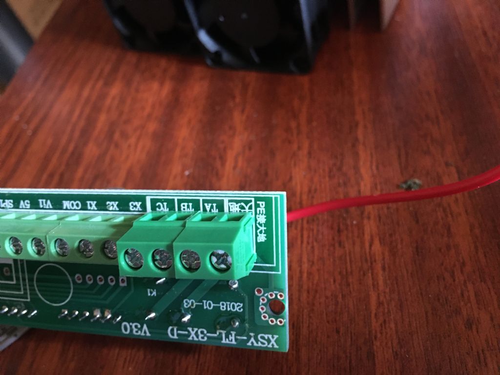
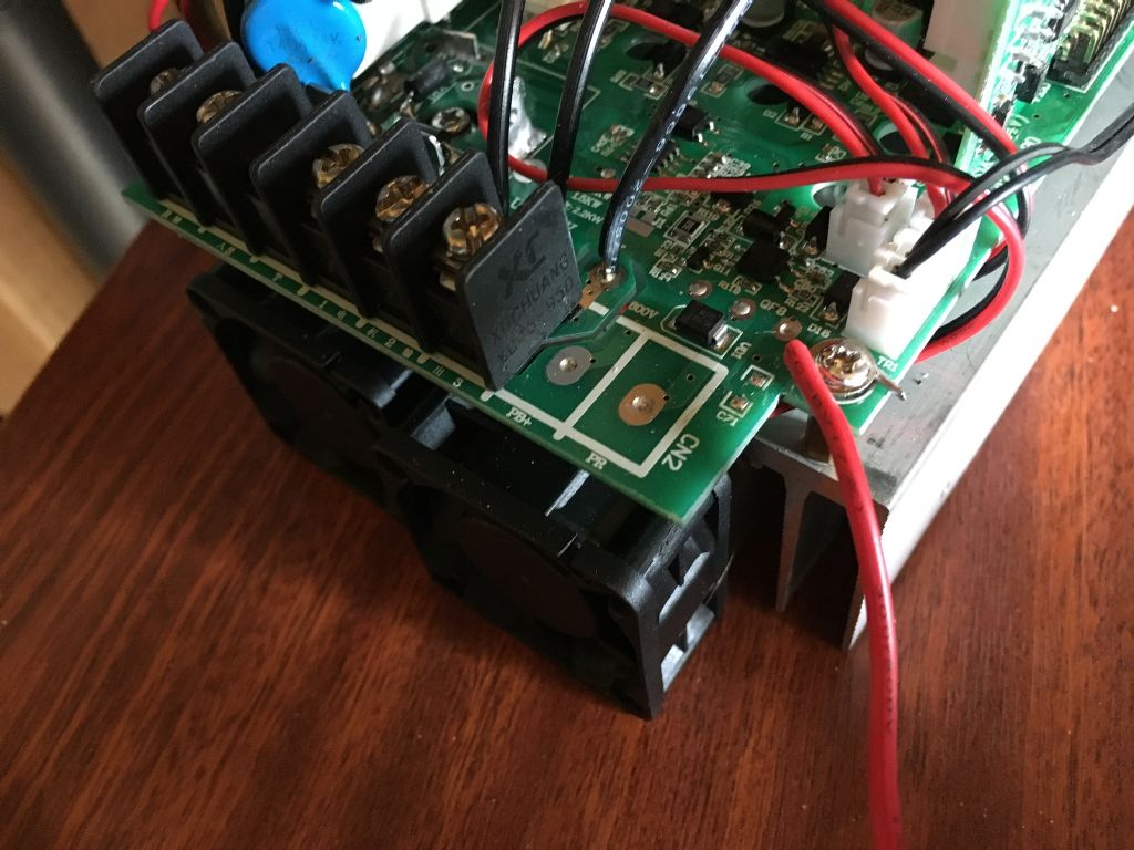
        The PE terminal is quite easy to see when the board is removed from the case. There is a red wire that connects the terminal and the main board and then through the brass board supports to the fins

        3fcf7c55-251c-42e1-8f83-90d130e3ac72.jpeg

        4774e486-a37c-4d6c-9941-1e50b017f6e5.jpeg

        The pot is new with a measured resistance of 10.7K . It seems ok but I don’t have any others to swap it with – awaiting a couple from China. I have set P10 and P11 to 2.

        I’ve checked the voltage between fins and a mains supply earth connected to the PE terminal and now get a reading of 3v ac down from 85v. Don’t know why it’s not zero but I guess one can live with 3v

        I’ve gone through all the “as supplied” parameters (including those not listed on the manual) on one vdf and once I’ve done it for the second one I’ll post a list listing all parameter settings “as supplied” .

        That protective earth (PE) connection looks pretty scary. Red insulation and a straght bit of solder tinned wire under a PCB mounting screw, The wire clearly is not large enough to carry fault currents on a system fused for 3kW (13A). Solder tinned wires (tin plated is different) should never be used under screw or crimp connections, The solder cold flows under pressure and a bad joint results. Used to be common with mains leads before pre-fitted plugs to find the leads solder tinned but this was found to be the cause of loose connetions and over-heaing plugs. Red wire on a PE is a technical breach of the acceptable standards.

        These things are a liability. As a minimum they must be inside a suitable enclosure. The user is legally responsible for making sure the installation is compliant with all relevant safety and EMI/EMC standards. In practice this does not happen.

        Robert G8RPI.

        #489235
        OneManEngineering
        Participant
          @onemanengineering
          Posted by James Walker on 02/08/2020 20:45:55:

          I always took P00 as being the max V that the unit could output. The reason being that P02 and P04 have a cap of either 220V or 380V which I believe is determined by P00. Anyway I have my P00 set at 380V and it is fed a 220-230V supply.

          Also if you have settings that you cannot change you need to input the default "0" password into P09. i.e. jusrt go into param update mode, go to input mode on P09 and "set" the value to 0. This should unlock everything. Did for me.

          Cheers,

          James.

          Well, I have tried! Still don’t work. I set P002 to 190V but P000 still don’t go over 220V.
          In fact if I try to spin up the motor this way it gives me I thing Err 01, which is over current protection!

          HOW DO YOU DO A FACTORY RESET ON THIS THING?

          Greg

          #489260
          Andrew Firman
          Participant
            @andrewfirman12129

            Greg,

            I’ve not done or found out how to do a factory reset, however a couple of other posters seem to have done so.

            I presume your terminals and labelling look identical to those in my photos. There seems to be a difference between an AT1 (220v) and an AT4 (380v).

            The only other external identification between an AT1 and an AT4 seems to be the label on the terminal cover. Ie someone could have fitted an AT4 terminal cover to an AT1 which might explain why you can’t set P000 to 380v

            I did once try to up load a file with all my parameter settings but couldn’t because it apparently had too many characters. I’ll try again in the next couple of days.

            #489270
            Martin of Wick
            Participant
              @martinofwick

              Greg,

              If it is truly an AT4, you should have no trouble setting P0 to default 380v and usually they arrive correctly programmed anyway. Check the boards as Andrew suggests. Usually AT1 have the earth on the incomer side and NOT on the control side as with the AT4 – but there could be variants.

              I strongly suggest before you resort to resetting, that you fully work your way through the manual and parameters and understand the important ones that relate to your intended operation. A full reset may result in some very strange parameter conditions and unintended consequences (in my experience).

              Set up on the bench and go through all of the significant parameters as stored in the device and write them down. try to check and change the ones you want again and check the running. Try to understand the manual – most of the info is there, just not in a helpful form.

              If you really want to do a full reset have regard to Parameter P77 and the associated reset condition 54321. but take heed, you are likely to get some unexpected consequences and may need to re enter some of the parameters you wrote down from interrogating the registers. In my case I was able to restore most functionality except for the ramp times which now requires dividing the required Hz/s by10!

              Take very, very great care with these AT4 devices, they output very high peak voltages at high currents.

              #489704
              OneManEngineering
              Participant
                @onemanengineering

                Guys, thank you ever so much for y'all input.

                I went back to the vendor and they asked me to go and have it fixed somewhere near me and they shall bear the costs. That means one thing I guess… yep its a sort of mutant between 220V and 380V. dang!

                Hence why it doesn't do what yours does.

                So I am now getting a new one, hopefully a working one this time.

                Greg

                #489706
                OneManEngineering
                Participant
                  @onemanengineering
                  Posted by Robert Atkinson 2 on 03/08/2020 11:43:44:

                  That protective earth (PE) connection looks pretty scary. Red insulation and a straght bit of solder tinned wire under a PCB mounting screw, The wire clearly is not large enough to carry fault currents on a system fused for 3kW (13A). Solder tinned wires (tin plated is different) should never be used under screw or crimp connections, The solder cold flows under pressure and a bad joint results. Used to be common with mains leads before pre-fitted plugs to find the leads solder tinned but this was found to be the cause of loose connetions and over-heaing plugs. Red wire on a PE is a technical breach of the acceptable standards.

                  These things are a liability. As a minimum they must be inside a suitable enclosure. The user is legally responsible for making sure the installation is compliant with all relevant safety and EMI/EMC standards. In practice this does not happen.

                  Robert G8RPI.

                  Hey Rob,

                  could you pls have a look at this:

                  **LINK**

                  What do you suggest what to do? I kind of figured I ground my motor to the VFD's PE, but you kinda made me change my mind. (This is the only ref point that I could call GND.)

                  What shall I Do?

                  Thanks, Greg

                  #490112
                  Bob Worsley
                  Participant
                    @bobworsley31976

                    Fascinating.

                    From the photos all I can see are two large electrolytic caps, are there any more? To boost the incoming 220V to 440V needs two caps, then you also need at least one smoothing cap on the 400V DC rail.

                    Can't read the voltage rating of the two obvious caps.

                    With extreme care, is it possible to measure the voltage on the two caps? If they are the boost caps then each will have about 240V or so, if the DC rail cap then it will have 440V or so.

                    If there isn't a 400V DC rail inside the VFD then not going to get 380V AC out.

                    #490131
                    Peter Bell
                    Participant
                      @peterbell11509

                      Not sure if its exactly the same as the one I looked inside but that only had the voltage doublers caps so I assumed they were also the smoothing caps.

                      It also had a small module to reduce the surge switch on when the cap were initially charging and the rail voltage was 660v dc..

                      Peter

                      #490134
                      john fletcher 1
                      Participant
                        @johnfletcher1

                        After all the discussion and theory to go with it, wouldn't be easier to dig out the motor Star point and bring out the 3 end to the terminal box , then buy a inverter with 3 Ph and 220 out. I remember some excellent picture on here together with an explanation of what to maybe a year or so ago. Its not so difficult to do, once you have the motor apart.. John

                        #490139
                        SillyOldDuffer
                        Moderator
                          @sillyoldduffer
                          Posted by Bob Worsley on 11/08/2020 11:14:09:

                          From the photos all I can see are two large electrolytic caps, are there any more? To boost the incoming 220V to 440V needs two caps, then you also need at least one smoothing cap on the 400V DC rail.

                          If there isn't a 400V DC rail inside the VFD then not going to get 380V AC out.

                          True, but no-one said how that high voltage rail should be produced.

                          In my youth, we said the transformer was too small if you could lift a power supply! Because everything worked at 50Hz, large components were essential. Voltage doublers and other compromises were common, despite their disadvantages. Modern designers have more choice. For example mains can be converted to any AC frequency he chooses. Then volts can be stepped up with a high-frequency transformer because at typical carrier frequencies (2kHz to 20kHz) they're tiny. Mice compared with the elephants needed to work efficiently at 50Hz.

                          Difficult to generalise about the merits of a VFD without studying it's circuit diagram, component ratings and cooling arrangements. I'd not fret about buying a high-voltage VFD if I needed one, especially now they're affordable.

                          Dave

                          #490148
                          Anonymous
                            Posted by Peter Bell on 11/08/2020 13:02:50:

                            It also had a small module to reduce the surge switch on when the cap were initially charging and the rail voltage was 660v dc..

                            Which is no surprise as that's what one needs to generate 400VAC phase to phase 3-phase if one wants the "neutral" point to stay fixed. If the "neutral" can vary then one can get away with 565VDC.

                            Except for very low power VFDs I would think that a front end PFC is a simpler way of producing higher DC link voltages. The circuit is more compact and doesn't need two large flying capacitors and associated switches which may need isolated gate drives. A PFC has the additional bonus that it reduces the filtering required on the mains input to the VFD in order to meet harmonic limits.

                            Andrew

                            #490393
                            Bob Worsley
                            Participant
                              @bobworsley31976

                              Undoubtably true, but the unit is 2.2kW and whilst all the semis are hidden on the heatsink just doesn't look big enough to have both a switching 230AC to 400DC converter plus all the 400V 3ph drivers? Can only see one quite small transformer.

                              What voltage rating are the two caps?

                              Seems to me that there is needed both smoothing caps at 230V and at 400V even with a switching voltage boost.

                              #511020
                              Andrew Firman
                              Participant
                                @andrewfirman12129
                                Posted by OneManEngineering on 08/08/2020 19:42:31:

                                Guys, thank you ever so much for y'all input.

                                I went back to the vendor and they asked me to go and have it fixed somewhere near me and they shall bear the costs. That means one thing I guess… yep its a sort of mutant between 220V and 380V. dang!

                                Hence why it doesn't do what yours does.

                                So I am now getting a new one, hopefully a working one this time.

                                Greg

                                Greg, I’m wondering how you solved your P00 220v issue.

                                I purchased another AT4 sometime ago and have only just got round to checking it.
                                It was supplied with P00 = 220 and I’m unable to increase above this value. My other two AT4s were supplied I believe with P00 = 380

                                I’ve queried this with the supplier and received a couple of responses. One states P00 is the input voltage! I’m asking them to reconfirm this and to clarify whether P02, which is Intermediate Voltage in the manual, is supply or output voltage.

                                #639359
                                Chris Brown
                                Participant
                                  @chrisbrown76250

                                  Hi I have an at4 vfd and I have been wiring it up and seem to be getting 500v output.seems very high.any help would be much appreciated.thanks

                                  #639367
                                  Robert Atkinson 2
                                  Participant
                                    @robertatkinson2

                                    What are you measuring it with and is a motor connected?

                                    Most normal multimeters will not measure the PWM output of a VFD accurately. As a minimum you need to use a True RMS voltmeter.

                                    Robert

                                    #639369
                                    Martin Connelly
                                    Participant
                                      @martinconnelly55370

                                      As Robert points out the voltage of a true sine wave AC supply is usually given as an RMS (root mean square) value. For 230V mains this means the peak voltage is the RMS voltage multiplied by the square root of 2, 325V. For a 380V RMS true sinewave the peak voltage will be 537V. For a VFD where a circuit chops the voltage to give an approximately sinusoidal voltage it would be likely that the peak is close to 500V. Without a load to feed it is possible that there are smoothing capacitors on the output that are charging to this peak voltage but not being allowed to discharge and so reach 500V and stay there. As the peak of a 380V AC supply is over 500V I would not worry about connecting a 380V motor to this VFD as they are built to take this voltage.

                                      RMS is the voltage of an AC supply that has the same output power as a DC supply at that voltage. A 230V RMS AC supply will cause the same heating effect in a 1kW heating element as a 230V DC supply. It is based on the area between a sine curve on a graph and the line passing through the centre of that sine curve. For an AC voltage that line is usually the X axis. This is how the square root of 2 ratio of peak to RMS is mathematically derived.

                                      Martin C

                                      #657012
                                      Robert Graham
                                      Participant
                                        @robertgraham80849

                                        I've just joined this Forum because this thread gave me an answer – which I have yet to check – to the same problem that the Original Poster asked – why does the internal potentiometer allows me to run a 4 pole 3 ph motor up to 100Hz but the external pot will only go up to 50 Hz.

                                        In my case I have a motor which is a 2 pole / 4 pole combination to allow 2 speed operation with an appropriate switching of the windings – there are 6 leads coming form the motor. I have done the internal change from star to delta on a previous motor but the thought of dismantling this motor and attempting to locate the star points put me off particularly when I found the AT4 – again a couple of years ago and have only got round now to trying it out.

                                        So thanks to all of you who previously fully discussed this out, and I am hoping the guidance will work.

                                        Rob

                                        #657131
                                        Robert Graham
                                        Participant
                                          @robertgraham80849

                                          Yep – the guidance works!! Again so many thanks even if those in the 2020 discussion are no longer seeing this.

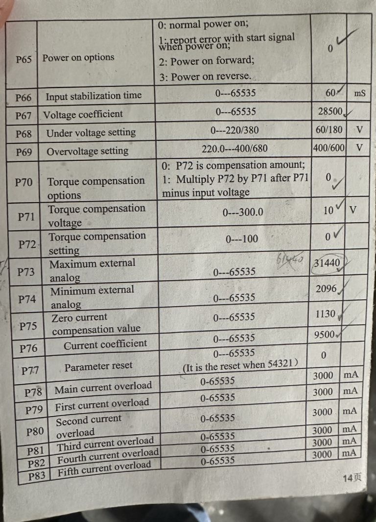
                                          The relevent list came from James Walker's posting of 25/05/2020, with particular reference to the settings for P73 and P74 – just how anyone found that these particular parameters are the key ones for this I just gasp at !!!

                                          Rob

                                          #657135
                                          Robert Atkinson 2
                                          Participant
                                            @robertatkinson2

                                            Welcome to the forum.
                                            Thanks for letting us know your outcome. Often the original poster never responds with th outcome wihich sometimes make you wonder if it is worth taking the time to post an reply.

                                            Robert.

                                            #657137
                                            Robert Graham
                                            Participant
                                              @robertgraham80849

                                              Thanks for that Robert – one then starts to think about the possible number of times you've fallen into that catergory; I do try to the polite thing but I'm sure I have been a guilty one too.

                                              But the other aspect is that you have shared your knowledge and, as in this case, I searched 2 years after the original discussion and found a treasure trove of info.

                                              i'm restoring a 1970's planer / thicknesser (for wood!) which has two 3 ph motors requiring the appropriate inverters.

                                              Rob

                                              #657163
                                              James Walker
                                              Participant
                                                @jameswalker31828

                                                @Robert G – On my mill the turret moor is is a Dahlander motor which means it is dual speed without having two windings. Anyway I leveraged those two full speed ranges with the VFD by adding a mechanical switch to switch the winding connections. It means I can leverage a lower speed while keeping the VFD stresses down on the old motor.

                                                This is possible with the AT4 as it is a simple Voltage/Hz style VFD which are able to run multiple motors of the same type at once. As compared to a Vector VFD which is tuned to the specific motor parameters. And when you switch poles those parameters change.

                                                There is one rule you need to live by so you dont blow your VFD, NEVER CHANGE THE POLES WHEN THE VFD IS DRIVIG THE MOTOR. The motor must be stationary and the VFD idle.

                                                cheers – James.

                                                #657171
                                                Robert Graham
                                                Participant
                                                  @robertgraham80849

                                                  Many thanks James for your comments and guidance.

                                                  I did expect this motor for driving the thicknesser rollers of the machine to be a Dahlander winding, but measurements show two seperate sets of coils; seemingly this is quite a popular format for large cooling fans, where a simple thermostat, and no electronics, will enable a higher cooling rate when required.

                                                  The motor, perhaps like yours, is probably classifiable as old but as it was also capable of running at 2800rpm, I'm using the 4 pole windings and taking the top frequency up to 100Hz. It's not going to be used on a commercial basis, just amateur, so won't get used heavily.

                                                  Out of interest how did you discover that it was P73 and P74 that had to be changed to get the external variable voltage to the bigger range?

                                                  Rob

                                                  #657173
                                                  James Walker
                                                  Participant
                                                    @jameswalker31828

                                                    Based on the description in my manual I figured that was probably what is was. Did some tests which proved my interpretation correct.

                                                    VFD Manual Page

                                                  Viewing 24 posts - 51 through 74 (of 74 total)
                                                  • Please log in to reply to this topic. Registering is free and easy using the links on the menu at the top of this page.

                                                  Advert

                                                  Latest Replies

                                                  Home Forums General Questions Topics

                                                  Viewing 25 topics - 1 through 25 (of 25 total)
                                                  Viewing 25 topics - 1 through 25 (of 25 total)

                                                  View full reply list.

                                                  Advert

                                                  Newsletter Sign-up