Posted by Michael Gilligan on 19/06/2017 07:40:44:
Posted by Tony Pratt 1 on 19/06/2017 07:22:19:
Hi Guys,
…
I can hear a massive amount of buzzing on the radio.
…
Tony
…
VFD basically synthesise their "sinewave" so it looks something like this: **LINK**
…
MichaelG.
…
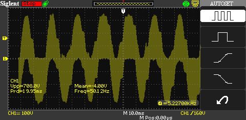
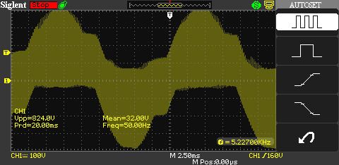
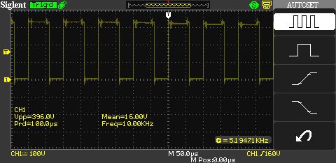
That's right, but the waveforms aren't so neat in the real world. Just for interest, here's some screenshots of the waveform output by my VFD on dead slow.
As you can see the waveform is a very rough approximation of a 50 Hz sine-wave.
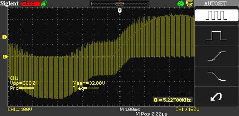
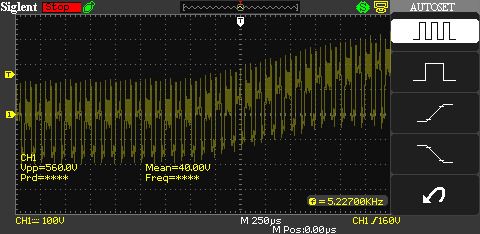
Zooming in on the detail reveals how it's been built up
The 50Hz 'sine wave' seen by the motor is synthesised from a 10kHz square wave. Square waves are wonderfully efficient because the semiconductor switches inside the VFD are either fully on or fully off, which means they don't get hot. But those very fast on-off transitions create radio frequency energy. While DC and AC tend to stay with the cable RF has no such limitation. Rapidly alternating currents produce mutually supporting electric and magnetic fields that expand to infinity. Although most of the power produced by a VFD behaves like 50Hz AC, a proportion of it is RF that will radiate if it can. A good way to stop it is with earthed metal shields and perhaps a filter..
Sharp spikes produced by VFDs might cause grief inside older motors (pre 1980, allegedly). Although most old 3 phase induction motors 'just work', there are reports on the web of insulation failures and unwanted currents flowing in the bearings.
RF currents produce counter-intuitive effects. If, for example, you connect a 50Hz power source to the base of a large air-cored inductor, nothing much happens. A 100kHz power source connected to the same coil will produce spectacular effects like a Tesla Coil. A Tesla coil can be made by accident. If your motor/VFD combination starts producing big sparks, suspect a loose connection. It's important to fix it quickly; although RF created voltages are unlikely to cause much damage in themselves, they can start an arc that ordinary AC will sustain with thoroughly bad results.
Dave
Edit: checked it twice and still didn't see the typos before hitting save.
While DC and AC tend to stay with the cable RF has no such limitation. Rapidly alternating currents produce mutually supporting electric and magnetic fields that expand to infinity. Although most of the power produced by a VFD behaves like 50Hz AC, a proportion of it is RF that will radiate if it can. A good way to stop it is with earthed metal shields and perhaps a filter.
By definition an RF signal is AC. They're one and the same thing, not different things. Any AC signal will radiate an electromagnetic wave, unless of course Maxwell got it wrong.
I'm afraid you're getting confused about Tesla coils. They are a resonant transformer, not a coil as such, and it is the Q of the resonant circuits, and the step up ratio, that allows very high voltages to be generated.
By the way the waveform you 'see' from the output of the VFD will depend upon whether you measure phase to phase or phase to 'neutral'.
Andrew
Yup. True that AC is RF, I have no argument with Maxwell.
What I was trying to say was that the tendency for a wire to radiate is much lower at 50Hz than at radio frequencies. An efficient antenna (half-wave dipole) at 50Hz would be 3000km long. In comparison domestic electrical wiring is much too short and close to the ground to radiate much. Radio Frequency AC is not nearly so constrained, an efficient transmitting antenna at 30MHz being only 5 metres long. Light is also AC and that doesn't behave much like 50Hz electricity at all.
Though I understand Tesla Coils to my own satisfaction I plead guilty to confusing everyone else. I started by saying 'like a Tesla Coil', meaning only that shoving a spike of energy into an inductor is liable to up the voltage at the other end. But then I said 'A Tesla coil can be made by accident' which is definitely misleading. You're right, the way a car ignition coil makes volts is not quite the same as a transformer, nor the same as a resonant transformer. I still suggest that: odd things happen when RF is about.
Good point about looking at the waveforms phase to phase, which is what the motor actually gets as input. I'd have put my oscilloscope across two of the phases except I couldn't think of a quick way of doing it without accidentally shorting one of them to earth. It's too hot for that kind of excitement today.
Being concerned that my invertor did not back radiate any unpleasant RF into the mains (did not want to mess up anything in our house or any other house connected to the same phase), I fed it through a (secondhand) suppressed mains socket. After nearly fourteen years, there seem to have been no problems.
This is UK, running off a 13 Amp 240 volt socket, 50 Hertz, with the feed coming from the house through a RCD.
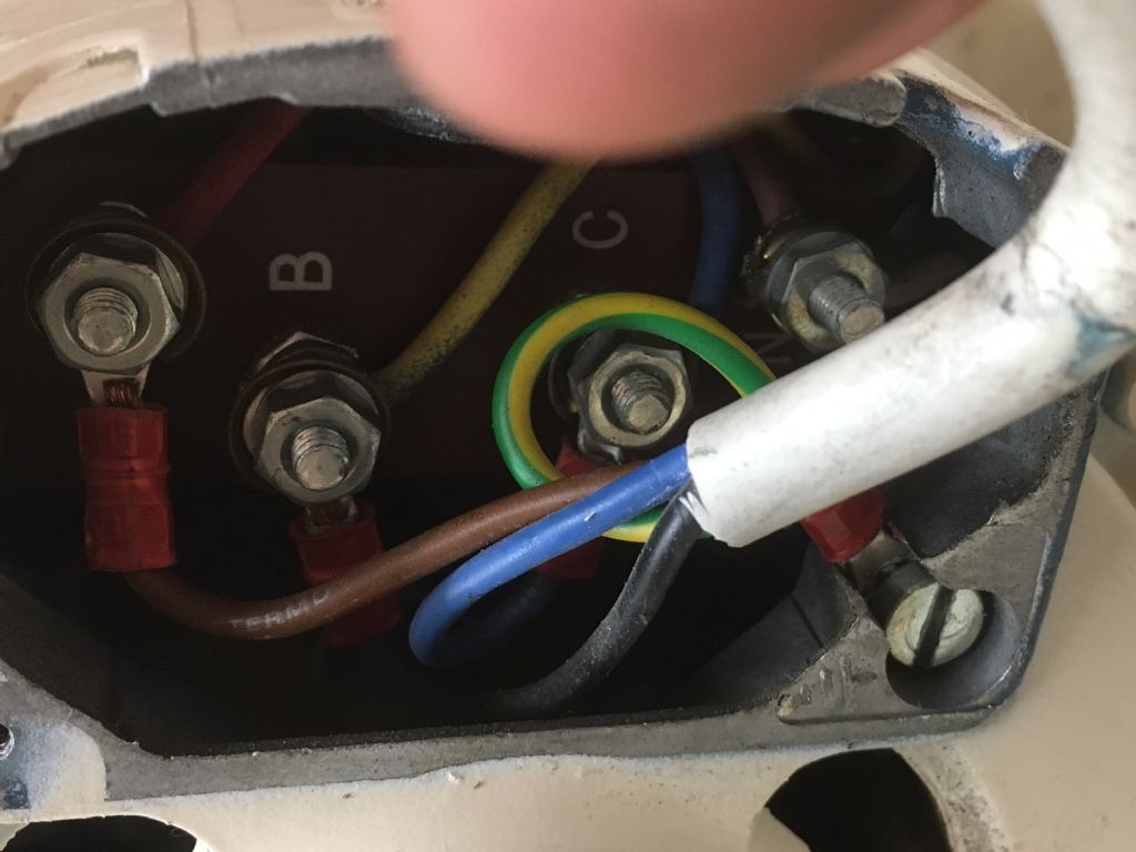
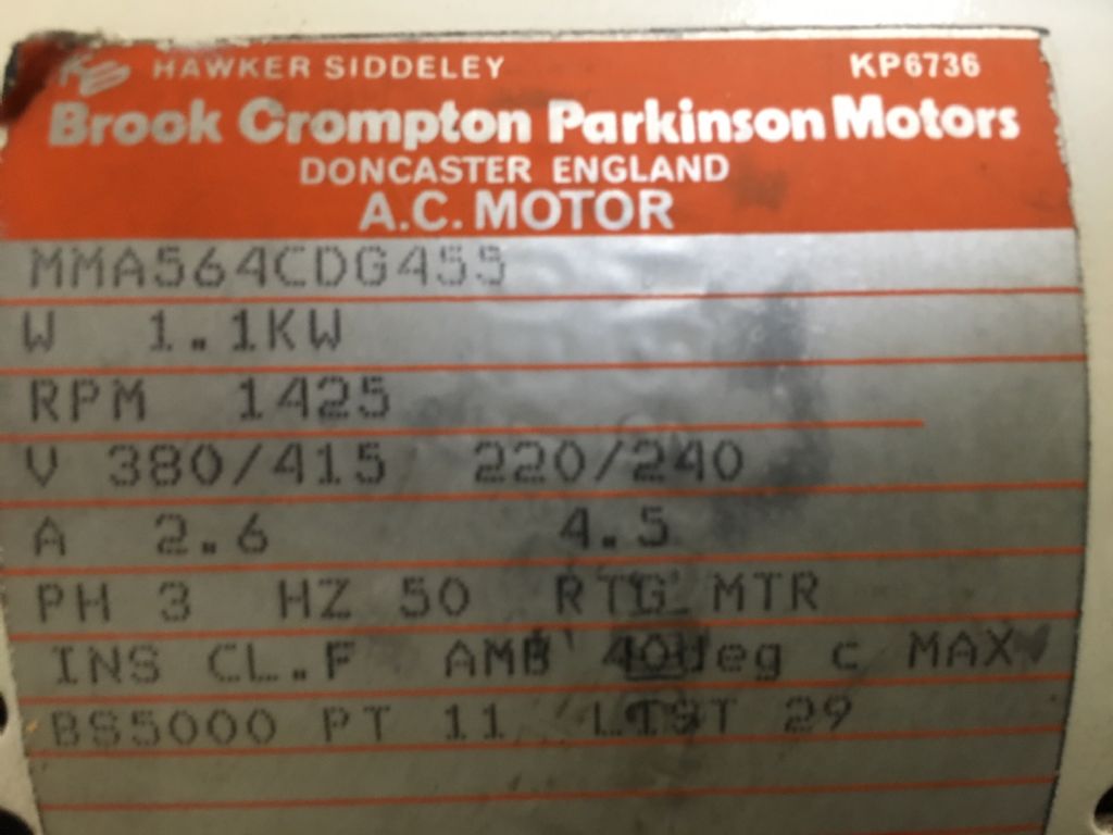
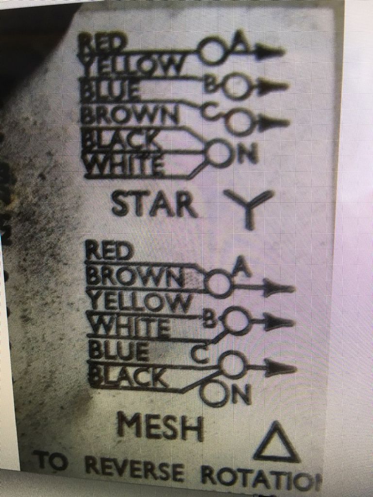
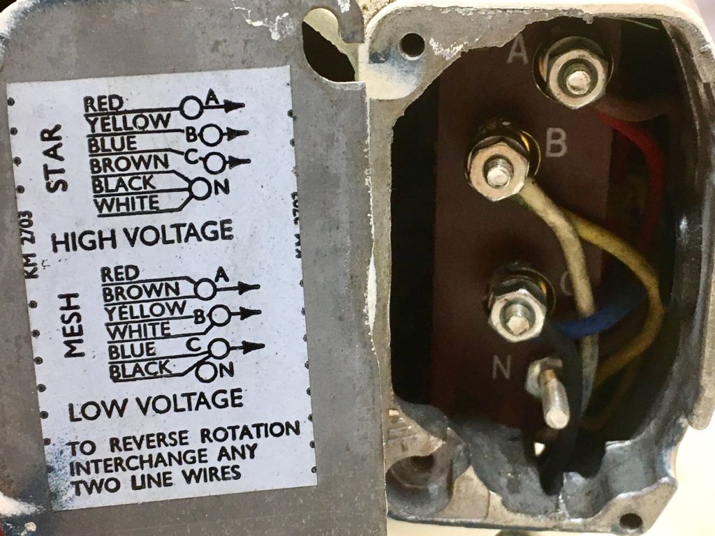
some picture of the Star wiring that i need to make Mesh/Delta so i can then connect the Inverter which i believe connects from U,V,W to any of ABC on the motor.
i have seen a few posts on it but no simple explanations i.e remove all wires and connect Colour/Wire to A,B,C,N etc
The white cable in the picture is going to the electrical control unit on the lathe itself so i presume that will be disconnected altogether and the remaining wires i are to the motor which then need connecting Brown to A, White to B and Black to C with nothing on N to make it Mesh/Delta
You can set the carrier frequency of an IMO Cub anywhere between 0.75 and 15Khz, which should provide a way of reducing any interference left after improving the screening to avoid your favourite radio station (or target the one your neighbour listens to).
Do read the manual on the pros and cons cf changing the frequency:
Lowering the carrier frequency increases the ripple components (harmonic
components) on the output current waveform so as to increase the
motor's power loss and raises the temperature of the motor. If the carrier
frequency is set at 0.75 kHz, for example, estimate the motor output
torque at 85% or less of the rated motor torque.
On the contrary, raising the carrier frequency increases the inverter’s
power loss and raises the temperature of the inverter. The inverter has a
built-in overload protection function that automatically decreases the
carrier frequency to protect the inverter. For details about the function,
refer to function code H98.
In that case, connect the coloured motor wires as per the diagram, for Mesh, then use the White cable ( if its long enough..) connecting to terminals U,V and W on the inverter, the free end to terminals A,B and C on your motor.
There should be no wires connected to the N terminal.
Good point about looking at the waveforms phase to phase, which is what the motor actually gets as input. I'd have put my oscilloscope across two of the phases except I couldn't think of a quick way of doing it without accidentally shorting one of them to earth.
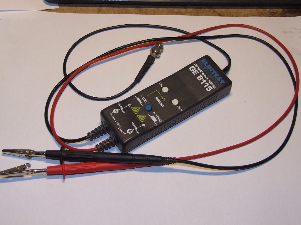
You need one of these:
….a differential probe. Essentially the potential divider is split on either side of the measurement resistor. So the ground of the 'scope' may be connected to ground on the EUT but through many megaohms, so not a problem.
I bought mine to look at gate drive and output signals on high current (2500A) half bridges running from rectified three phase.
You could let the scope float by disconnecting the earth, to indicate the earth was disconnected we used to have a long earth and pull it out of the plug top so you could see it, I had a nice shock one day when I had the bare croc clip in my hand and leaned on the chequer plate platform round the machine, the earth cable in the plug top had been left long enough to touch the live pin of the 13amp top in the days before pins were shrouded to protect small fingers so the scope was live. A pretty dodgy setup at the best of times but it works, sooner or later it will bite you though. My boots must have been good insulators as I didn't even get a tingle until I was earthed. Why is an electric shock so hilarious for everyone but the victim? although I was on the receiving end that time I still can't help laughing when it's someone else.
Differential probes eh! I've been messing with oscilloscopes for 50 years and this is the first time I've heard of such a thing. I wonder what else I've missed? The older I get the more I realise I've not being paying attention. They're a bit dear though. uYAAOxyCepSa8EO”>LINK
Edit strange corruption of the ebay link. And now it's attached to my signature. Weird.
You could let the scope float by disconnecting the earth, to indicate the earth was disconnected we used to have a long earth and pull it out of the plug top so you could see it, I had a nice shock one day when I had the bare croc clip in my hand and leaned on the chequer plate platform round the machine, the earth cable in the plug top had been left long enough to touch the live pin of the 13amp top in the days before pins were shrouded to protect small fingers so the scope was live. A pretty dodgy setup at the best of times but it works, sooner or later it will bite you though. My boots must have been good insulators as I didn't even get a tingle until I was earthed. Why is an electric shock so hilarious for everyone but the victim? although I was on the receiving end that time I still can't help laughing when it's someone else.
Mike
When I worked in an electronic repair shop, one of my colleagues used this trick. A certain piece of kit had a logic board where for some reason the signal ground was floating at I think about 350V DC. Highly unsafe, but apparently the only way to troubleshoot. Everyone kept well clear when he was working in this way.
The power on/off switch on the lathe has had a 3 phase plug on the end that has been removed and I now have 4 wires which I'm not sure I need with the inverter and control pendent and if I need it connected or not but it would be good to have the power switch on the lathe working as opposed to just using the isolation switch to turn it on