VFD wiring

Advert

VFD wiring

Home Forums Electronics in the Workshop VFD wiring

Viewing 25 posts - 26 through 50 (of 81 total)
  • Author
    Posts
  • #303019
    Roderick Jenkins
    Participant
      @roderickjenkins93242

      Yes: The Wi-Fi router doesn't work while I'm using the VFD driven lathe.

      Cheers,

      Rod

      Advert
      #303043
      SillyOldDuffer
      Moderator
        @sillyoldduffer
        Posted by Mike Poole on 17/06/2017 23:04:15:

        Has anybody actually experienced any problems with interference from their VFD if they have not followed recommended guidelines?

        Mike

        Just spent a happy couple of hours conducting an EMC review of my workshop.

        I used an SDRPlay RSP1 covering 10kHz to 2GHz. The receiver is connected via a USB cable to an Acer Aspire V15 laptop running Windows 10. The RSP1, which is a Software Defined Radio, was managed by SDRConsole v3 set to decode Amplitude Modulation (AM). The antenna was 10m of wire looped around my dining room and it is about 8 metres distant from the lathe as the crow flies.

        I make no claims for calibration not least because the antenna is a complete lash-up. Therefore my assessment of my lathe's EMC as 'very poor' does not mean that it is out of specification, only that I'm not impressed.

        Results:

        • The laptop's switch mode power supply lifts the radio noise floor by 10dB, the racket gradually fading away at about 150Mhz. (Poor) Therefore the workshop tests were run with the laptop on battery only.
        • I can just detect 6 tubes of fluorescent lighting around 125kHz. (Very Good)
        • I can detect an impulse when the grinding wheel is started, but it is otherwise fully suppressed. (Very Good) Ditto the band-saw.
        • My cheap pillar drill is nearly as good as the grinding wheel (impulse start detected), except for minor noise centred around 500kHz. (Very good)
        • My small belt-sander is nearly as good as the grinding wheel (impulse start), except for some hash centred around 3.6MHz. (Very good)
        • Best of all – no interference detected – was my Milling Machine. It has an 1100W brushed DC motor. (Very good)
        • In comparison the 1500W VFD in the lathe is very poor, see pictures and comments below.

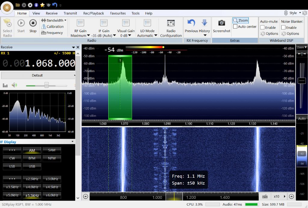
        When the lathe's electronics are switched on but the motor is off, a series of moderately strong signals appear. They are unstable, about 80kHz apart and peak in strength at about 1MHz . This is inside the medium wave broadcast band. The strongest spur measured -54dB compared with a nearby radio station at -48dB. (ie the radio station is only twice as loud as the lathe. There is potential for interference even before the motor starts.)

        vfd_motor_stopped.jpg

        In the picture above the two strong white lines are interference from lathe and there is an AM broadcast station between the spurs. By luck the lathe is not interfering with that particular broadcast, phew!

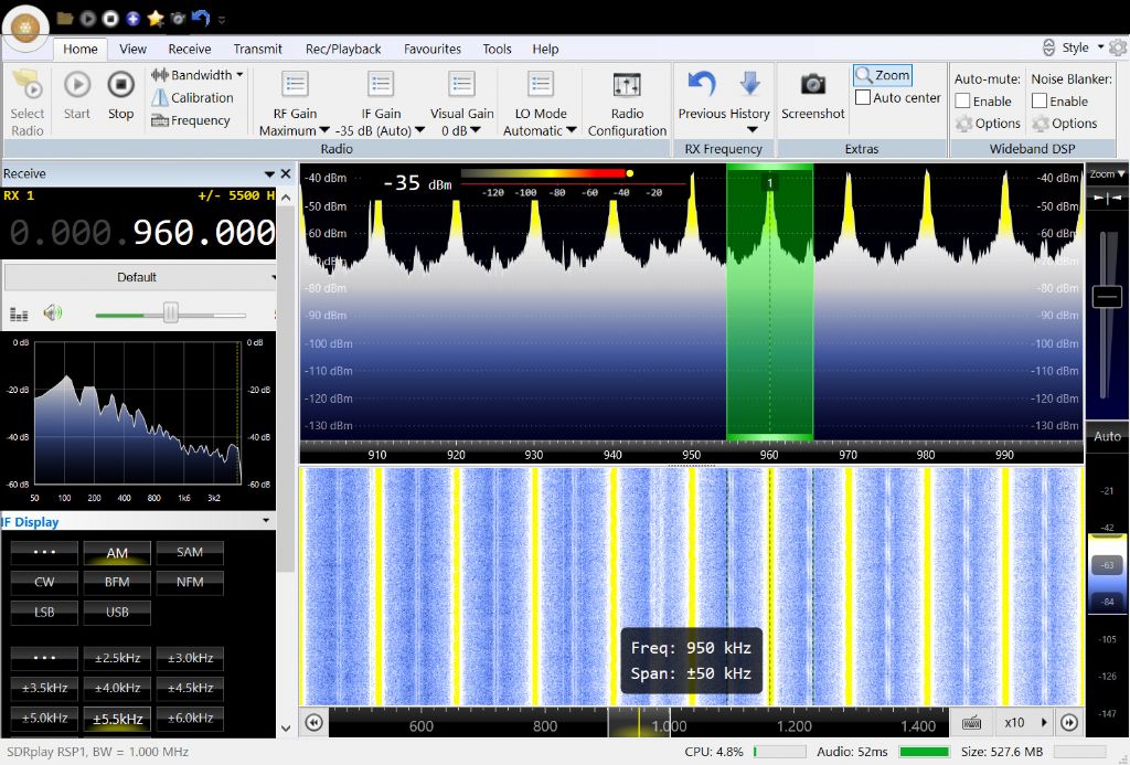
        Unfortunately the interference gets much worse when the lathe's motor is switched on.

        vfd_motoring.jpg

        The picture shows heavy interference. It starts at 10kHz with harmonics every 10kHz. Although the signals peak in the medium wave band, they remain powerful up to about 20MHz and can still be just detected at 50MHz. Bad news. The interference is considerably strong than broadcast radio in the medium waveband and all stations are wiped out.

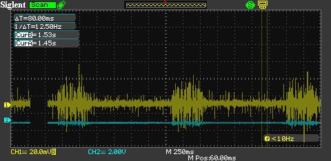
        The signals are far from pure being modulated with bursts of noise every second or so.

        vfd_modulation.jpg

        Being inside the house the antenna emphasises near source radio interference. Next step is to see how far away from the house I can detect lathe generated interference on an AM portable. If the interference is being carried by the mains cabling rather than radiated directly it could be quite a long way. Like miles! I'm hoping that I'm picking up short range interference and that the VFD filter is keeping most of the muck out of the mains wiring.

        My workshop DAB radio is not interfered with. DAB signals are broadcast at about 240Mhz which is too high to hear the lathe's VFD. There is no problem with TV. I haven't tested the effect on the Internet yet.

        Before throwing rocks at the lathe and it's VFD I need to do more checking. One obvious problem is that in the workshop the lathe is on the end of a longish lead, and that the workshop itself is in an extension somewhat distant from the consumer unit. The actual earth could be 30 metres away from the lathe, fine as a safety earth, but total poo when it comes to grounding radio frequencies. Or it might not be that at all.

        It's too early to suggest a fix, or even to conclude the bad results matter much in practice. Interesting though…

        Dave

        #303046
        Muzzer
        Participant
          @muzzer

          Would be interesting to know a few basic details about the lathe and its VFD. Is this part of the original machine or was it a retrofit? Does it actually have an EMC filter on the input? How is the machine grounded? How is the VFD housing itself grounded and ideally bolted to the machine? Have you got shielded motor cables?

          Murray

          #303054
          Jez
          Participant
            @jez
            Posted by Mike Poole on 17/06/2017 23:04:15:

            Has anybody actually experienced any problems with interference from their VFD if they have not followed recommended guidelines?

            Mike

            Yes – our fridge / freezer was pretty unhappy on the other side of the wall from my milling machine. A large ferrite on the mains input sorted it out.

            #303058
            SillyOldDuffer
            Moderator
              @sillyoldduffer
              Posted by Muzzer on 18/06/2017 12:42:32:

              Would be interesting to know a few basic details about the lathe and its VFD. Is this part of the original machine or was it a retrofit? Does it actually have an EMC filter on the input? How is the machine grounded? How is the VFD housing itself grounded and ideally bolted to the machine? Have you got shielded motor cables?

              Murray

              Yes, no problem. I've just retreated from the garden where I'm pleased to report that the interference appears to be much lower. But, having wasted a lot of time looking for a portable radio and suitable batteries I find it's too hot and humid to walk far. Also got hay-fever so I'm going to look inside the lathe next.

              Is this part of the original machine or was it a retrofit? The lathe is a Warco WM-280 VS fitted as delivered with a Delta VFD. The motor is 1500W.

              Does it actually have an EMC filter on the input? Yes according to the circuit diagram – I'm going to check that it's actually connected.

              How is the machine grounded? Through the mains plug. (I think this is a problem.)

              How is the VFD housing itself grounded and ideally bolted to the machine? It's enclosed in a metal box that forms the rear of the lathe, i.e built-in around the headstock. The VFD box is mounted on a metal rail system that I believe to be screwed to the headstock but I need to check. (Difficult to see.) All the metal parts of the lathe are earth strapped.

              Have you got shielded motor cables? I suspect not. Should be easy to confirm once I have the back off.

              Dave

              #303070
              SillyOldDuffer
              Moderator
                @sillyoldduffer

                I've opened Pandora's box and looked at my lathe's wiring:

                • A 3-neon ring-main tester shows L,N and E correct
                • There are 0 volts between N and E
                • DC resistance from Neutral to Earth at the lathe is a little under 1 ohm
                • the mains input cable is unshielded
                • the wires to the interlock switches, main on/off switch and to the cooling fan mounted on the motor are all unshielded.
                • the cable to the front panel control potentiometer is shielded
                • the removable front panel has an earth wire.
                • all the earth wires connect to a common copper strap about 4mm thick. The connecting bolts clamp the strap to the headstock
                • All exposed metal parts read 0 ohms back to the mains earth
                • The filter isn't connected as a filter! The filter board has mains input and provides power feed (probably 5V) to the tachometer. Nothing is connected to the mains voltage output terminals. The input-side capacitors will provide basic suppression, but that's all. I doubt that the filter components are man enough to take the 6.9 Amps needed to run the lathe. Nor is the board shown as an input-output filter by design on the circuit diagram.
                • The 3 VFD to motor wires are unshielded except where they pass through plastic conduit from the headstock to the motor's terminal box. The plastic conduit has an internal metal shield but it's not confirmed that it's connected. Poking at the gland with a multimeter failed to find a ground. I think the conduit shield is floating.
                • The VFD to motor wires, which should be short, are about 200mm long. (Good)

                So, nothing outrageous and a couple of obvious fixes to try. It will be easy to replace the motor wires with a shielded cable, and I have a beefy mains filter that can be put in-line with the lathe provided I can box it up safely.

                I'm concerned about the radio earthing though. My house has PME which I've never understood. Any suggestions?

                Thanks,

                Dave

                #303073
                Michael Gilligan
                Participant
                  @michaelgilligan61133
                  Posted by SillyOldDuffer on 18/06/2017 16:23:04:

                  … My house has PME which I've never understood. …

                  .

                  This is a useful start, Dave: **LINK**

                  https://www.tlc-direct.co.uk/Book/5.6.1.htm

                  MichaelG.

                  #303078
                  Mark P.
                  Participant
                    @markp

                    I grounded both ends of the braiding, in fact I grounded everything, no problems what so ever.
                    Mark P.

                    #303079
                    ChrisH
                    Participant
                      @chrish

                      Muzzer & John S.

                      Definition of an 'Expert'. An 'ex' is a has-been, and a '(s)pert' is a leak under pressure. QED.

                      Life can get too serious!

                      Chris

                      #303097
                      Neil Wyatt
                      Moderator
                        @neilwyatt

                        > -54dB compared with a nearby radio station at -48dB. (ie the radio station is only twice as loud as the lathe.

                        6dB difference is four times

                        #303099
                        Neil Wyatt
                        Moderator
                          @neilwyatt

                          10kHz sounds about right for the switching frequency of teh inbverter, in which case it is almost certainly the motor supply wires radiating the interference.

                          The pot connection is screened to stop spurious command signals getting in to a high impedance connection. I wouldn't expect the other control wires to be shielded.

                          N.

                          #303101
                          Muzzer
                          Participant
                            @muzzer

                            6dB is actually a factor of 2, given that we are talking about voltages. For power, 6dB would be a factor of 4 (= 2 squared).

                            The heat is getting to you!

                            Murray

                            #303103
                            SillyOldDuffer
                            Moderator
                              @sillyoldduffer
                              Posted by Neil Wyatt on 18/06/2017 21:01:48:

                              > -54dB compared with a nearby radio station at -48dB. (ie the radio station is only twice as loud as the lathe.

                              6dB difference is four times

                              2 x 2 = 4? Oh no, it's just like being back at school… crying

                              #303106
                              SillyOldDuffer
                              Moderator
                                @sillyoldduffer
                                Posted by Muzzer on 18/06/2017 21:11:54:

                                6dB is actually a factor of 2, given that we are talking about voltages. For power, 6dB would be a factor of 4 (= 2 squared).

                                The heat is getting to you!

                                Murray

                                I'm overheating too. We are indeed talking voltages. Now I've made a complete decibels of it I might take a cold shower.

                                #303111
                                john fletcher 1
                                Participant
                                  @johnfletcher1

                                  Talking of filters, has any one tried an ex washing machine filter unit, there are plenty about and ok up to 3 KW. For inverter control circuit I use a length of ex computer screened multi core, again miles of it finds its way the local recycle centre. John

                                  #303112
                                  Bob Brown 1
                                  Participant
                                    @bobbrown1

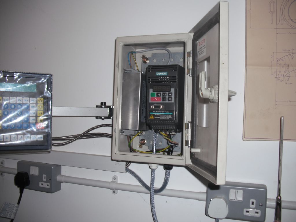
                                    I have an EMC filter fitted in the box along side the VFD to the mill dscf0078.jpg

                                    #303125
                                    Tony Pratt 1
                                    Participant
                                      @tonypratt1

                                      Hi Guys,

                                      I fitted a VFD to my mill some few years ago as per instructions [I think], since then as soon as I switch it on I can hear a massive amount of buzzing on the radio.

                                      Just an inconvenience but in layman's terms what is occurring & what is the simplest fix?

                                      Tony

                                      #303127
                                      Michael Gilligan
                                      Participant
                                        @michaelgilligan61133

                                        Posted by Tony Pratt 1 on 19/06/2017 07:22:19:

                                        Hi Guys,

                                        I fitted a VFD to my mill some few years ago as per instructions [I think], since then as soon as I switch it on I can hear a massive amount of buzzing on the radio.

                                        Just an inconvenience but in layman's terms what is occurring & what is the simplest fix?

                                        Tony

                                        .


                                        Tony,

                                        The good ones are much better these days, but … VFD basically synthesise their "sinewave" so it looks something like this: **LINK**

                                        https://goo.gl/images/3xhJNF

                                        … and all those square rising edges generate broad-spectrum signals

                                        [ look-up Fourier Analysis if you want more ]

                                        .

                                        The quick fix is to add a filter to the output, which smooths-out the ragged edges.

                                        … or buy a better VFD

                                        MichaelG.

                                        .

                                        Edit: clarified the proposed filter location.

                                        Edited By Michael Gilligan on 19/06/2017 08:07:06

                                        #303129
                                        David Jupp
                                        Participant
                                          @davidjupp51506

                                          VFD may or may not already contain an input filter (not always easy to find this out, but cheaper ones often don't). Fit the whole thing in a metal enclosure (unless it is specifically designed for use without a cabinet), if adding a filter on the mains input it should be mounted to the backplane of the cabinet, close to the VFD. Make sure cabinet and motor are earthed. Cable between VFD and motor should be screened 4 core (see the document I linked to earlier for typical recommendations about connecting the screen to earth) EMC rated cable gland may be helpful especially at the motor end to ensure good contact of screen to earth.

                                          Earthing and screening is important for the filtering to work correctly.

                                          #303130
                                          Anonymous
                                            Posted by Michael Gilligan on 19/06/2017 07:40:44:

                                            The good ones are much better these days, but … VFD basically synthesise their "sinewave" so it looks something like this: **LINK**

                                            https://goo.gl/images/3xhJNF

                                            … and all those square rising edges generate broad-spectrum signals

                                            That's odd, I was under the impression that a VFD output is PWM, with the pulse width varying sinusoidally. So nothing like the waveforms shown in the link. That way you don't need a linear (inefficient) output stage.

                                            The radio problem is almost certainly caused by radiated emissions from the VFD to motor cable. If the radio is battery powered, and still suffers from interference, that would confirm radiated, rather than conducted, emission.

                                            Andrew

                                            #303133
                                            Michael Gilligan
                                            Participant
                                              @michaelgilligan61133
                                              Posted by Tony Pratt 1 on 19/06/2017 07:22:19:

                                              Hi Guys,

                                              I fitted a VFD to my mill some few years ago

                                              .

                                              Andrew,

                                              I defer to your wisdom

                                              My suggestion was promted by Tony's opening comment ^^^ and his request for 'layman's terms"

                                              MichaelG.

                                              .

                                              P.S. … even with a PWM output, isn't it the fast rise-times that cause the problem. ?


                                              Edited By Michael Gilligan on 19/06/2017 08:50:41

                                              #303135
                                              Muzzer
                                              Participant
                                                @muzzer

                                                The voltage on the output will be swinging through 340V or so in as little as tens of nanoseconds – and back again 10,000 times per second in this case. The limits for the allowable voltage ripple sent back up the mains is of the order of mV, so you can imagine how easy it would be for a poor design to exceed that. I've spent hundreds, possibly thousands of hours of my life working on EMC compliance and it's difficult work – a lot more than just adding caps and chokes here and there.

                                                Generally, radio emissions (through the air) are likely to arise from the VFD to motor wiring and conducted emissions from the mains connection. However, the limits are very tight so you usually need to address all areas to stand a chance of compliance.

                                                It's possible to get an "output choke" for connection between the VFD and the motor. This will limit the voltage dV/dt and help emissions but you must be careful not to fit a "normal" EMC filter complete with X and Y caps or you may blow the VFD or cause a fire in the filter.

                                                Most VFDs don't seem to come with EMC filters although you can often buy them as options. So you can imagine the EMC sh**storm caused by many of the cheaper ones used without one.

                                                I believe that many of these home workshop machines are in some way exempt from the mainstream EMC regulations although I have no experience or understanding of how that comes about. But there is no law stopping you splicing a Chinese VFD onto your own machines and making a right pig's ear of it.

                                                Murray

                                                #303141
                                                SillyOldDuffer
                                                Moderator
                                                  @sillyoldduffer
                                                  Posted by Tony Pratt 1 on 19/06/2017 07:22:19:

                                                  Hi Guys,

                                                  I fitted a VFD to my mill some few years ago as per instructions [I think], since then as soon as I switch it on I can hear a massive amount of buzzing on the radio.

                                                  Just an inconvenience but in layman's terms what is occurring & what is the simplest fix?

                                                  Tony

                                                  Hi Tony,

                                                  I too am looking for a 'simple fix' and as Muzzer points out EMC can be tricky.

                                                  In my case the VFD is already inside an earthed metal enclosure (with ventilation and a fan to stop it overheating). That's the first step. See Bob Brown's photo for a good example; you can also see he's used shielded cables.

                                                  What I've found on my lathe is that the cabling between the VFD and the motor is not shielded as well as it could be. This is by far the most likely cause of my problem. As per David Jupp's advice I'm going replace the cabling with a shielded type (link thanks to Michael Gilligan) and make sure the shield connects to metal as soon as it enters the enclosure. Another point, the wires connecting the VFD to the motor should be as short as possible. The Mitsubishi guidelines mention a maximum of 50cm.

                                                  A third possibility is that a filter is needed on the mains input to stop VFD generated has escaping into the mains. John Fletcher suggested a Washing Machine type, which is what I'll try if shielded cable to the motor doesn't work.

                                                  Quick fix for your radio: replace it with a Digital type. Mine cost £20 from a supermarket. It's a selfish cure – don't forget your neighbours have radios too.

                                                  Dave

                                                  #303143
                                                  Anonymous
                                                    Posted by Michael Gilligan on 19/06/2017 08:38:56:

                                                    P.S. … even with a PWM output, isn't it the fast rise-times that cause the problem. ?

                                                    Correct. The harmonic spacing will be set by the basic PWM frequency, normally a few kilohertz. The amplitude of the harmonics will be determined by the speed of the edges and the exact characteristics of the PWM signal.

                                                    Andrew

                                                    #303145
                                                    David Jupp
                                                    Participant
                                                      @davidjupp51506

                                                      Posted by SillyOldDuffer on 19/06/2017 10:45:16:

                                                      Another point, the wires connecting the VFD to the motor should be as short as possible. The Mitsubishi guidelines mention a maximum of 50cm.

                                                      The 50cm max in the Mitsubishi document is Input Filter to VFD cable length. Long motor cables are best avoided, but shouldn't become a huge problem until quite a lot beyond 50cm.

                                                    Viewing 25 posts - 26 through 50 (of 81 total)
                                                    • Please log in to reply to this topic. Registering is free and easy using the links on the menu at the top of this page.

                                                    Advert

                                                    Latest Replies

                                                    Viewing 25 topics - 1 through 25 (of 25 total)
                                                    Viewing 25 topics - 1 through 25 (of 25 total)

                                                    View full reply list.

                                                    Advert

                                                    Newsletter Sign-up