Using DRO’s

Advert

Using DRO’s

Viewing 6 posts - 1 through 6 (of 6 total)
  • Author
    Posts
  • #69371
    Steve Talbot 1
    Participant
      @stevetalbot1
      I am in the process of researching the fitting of DRO’s to my Warco VMC mill.
       
      At the moment I use the table limit stops.
       
      Do those of you already having the benefit of DRO’s still find you use the table travel stops?
      Advert
      #30335
      Steve Talbot 1
      Participant
        @stevetalbot1
        #69377
        Roger Vane
        Participant
          @rogervane67137
          Hi Steve,
           
          I’ve fitted DRO’s to my Warco VMC, together with new stop bars and stops to both X and Y axes.
           
          My X-axis scale is fitted to the front of the table avoiding any loss of Y-axis travel (as would be the case if the scale was to be fitted to the rear of the table). I used a slim scale for the X-axis and standard scales for Y and Z axes.
           
          I certainly use the stops on occasions, particularly when milling a pocket or slot with closed ends – just in case I drop into ‘sleep mode’ and over-run.


          #69384
          Steve Talbot 1
          Participant
            @stevetalbot1
            Hi Roger,
             
            That’s just the information I was seeking.
             
            I’ve also decided to mount the scale to the front of the table, but need to decide the best way to achieve this and still retail the locks, table stops and electrical stops.
             
            Do you have any photos of your installation?
             
            Incidently although I have been extra careful I’m finding a number of small dings and marks on the table and wonder if the CI is soft. Have you had any problems?
             
            Regards,
            Steve T
            #69440
            Roger Vane
            Participant
              @rogervane67137

              Hi Steve

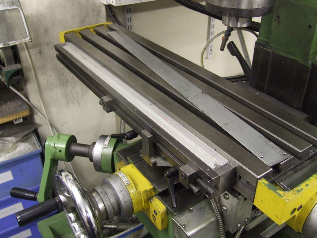
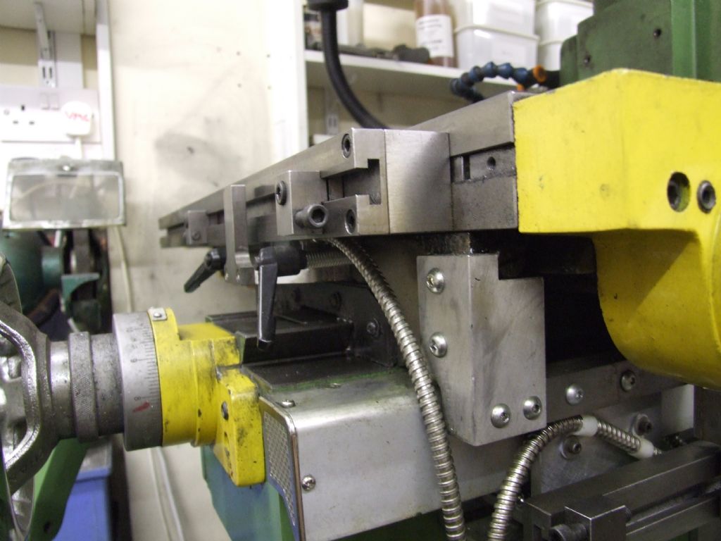
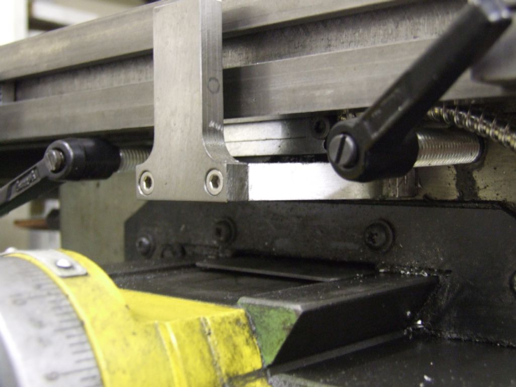
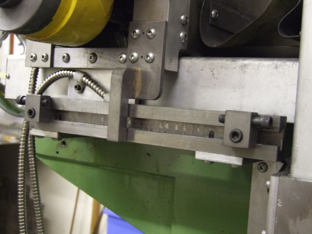
              As requested, here are a few photos of my DRO installation.

              X-axis

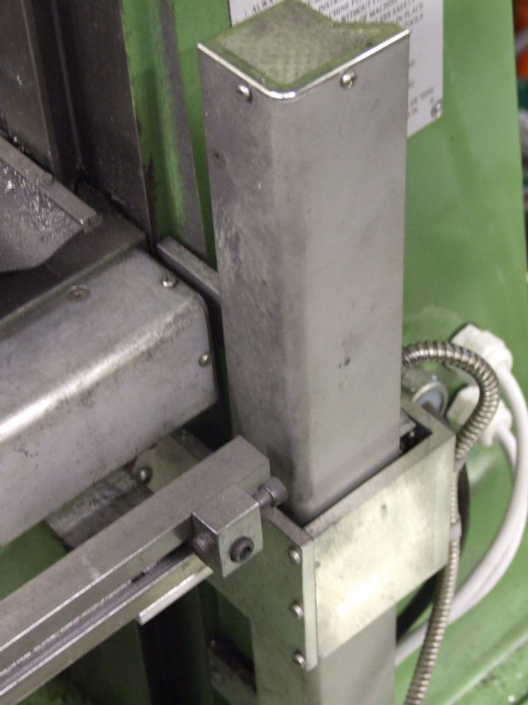
              The scale is attached into the existing stop ‘slot’ and then the new stop system is attached outboard of this, also into the existing slot. I made new dovetail nuts as those fitted to the machine were not very good and I also needed 2 more to attach the stop bar – the dovetail angle is 20 degrees inclusive and from memory are tapped M5.

              The stop bracket is basically ‘U’ shaped made from 3 pieces of alloy bar – one of the ‘uprights’ is screwed onto the machine saddle and the reader head is then screwed onto that – this gave the correct alignment of scale and reader head (after a little fine adjustment with the jacking screws). The stop itself is then attached to the horizontal member.

              There was just sufficient space to attach the scale, reader head and stop bracket when using the slim scale – the standard scales would just be too large for this to be viable on the VMC.

              I cut a T-slot in the new stop bar and made T-nuts as I found that the original dovetail nuts had ‘self-locking’ properties which would be irritating to use.

              The installation was completed with the addition of a sheet metal cover to protect the scales.
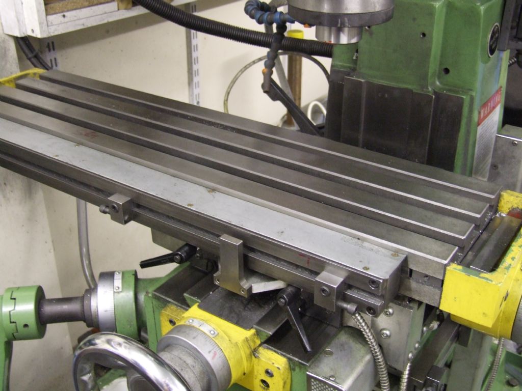
               

              The only problem that I’ve found with this installation is that the Z-axis feed handle hits the stop bar when the table is fully towards me and well to the left. This has not proved to be a serious problem.

              As you can see from the photos it is still possible to fit table locking screws – I replaced the standard screws with adjustable handles. As for the electrical stops, I see no reason why these could not be retained if fitted with T-nuts and used on the new stop bar.

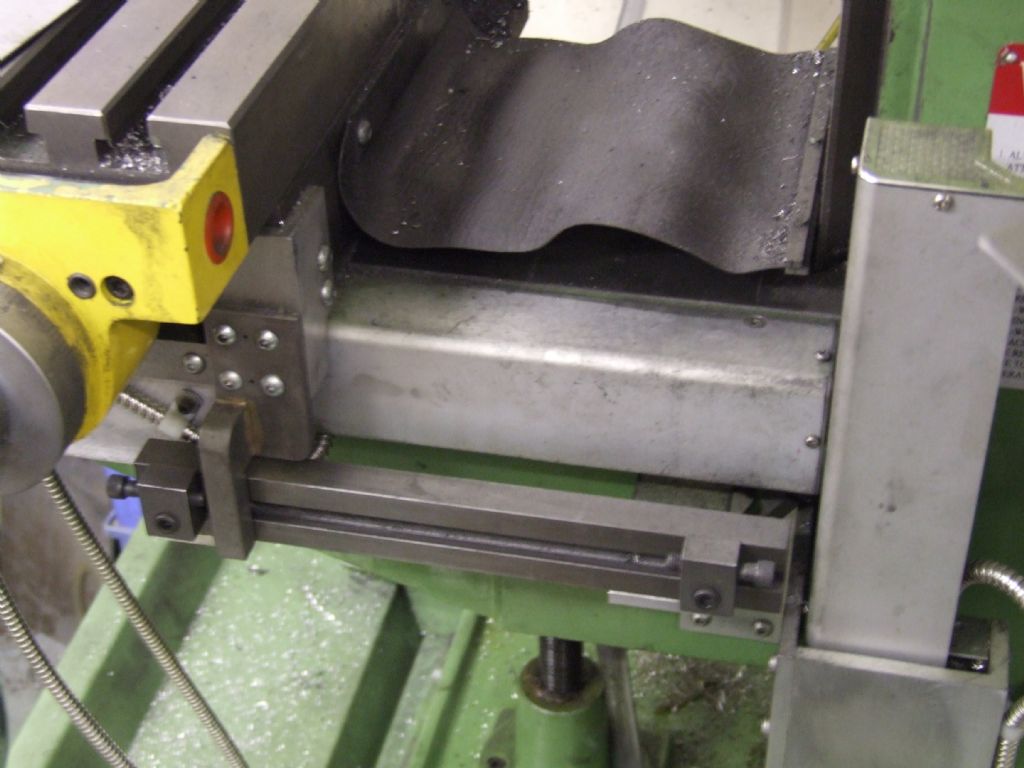
              Y-axis

              I employed a similar stop system to the X-axis. The scale was attached to the knee of the machine and the reader head was fitted to a bracket attached to the saddle. The stop bar was then fitted ‘outboard’ of this arrangement (on the knee), with the stop itself then fitted to the saddle of the machine.
              Marks on table

              No problems so far, but I suspect that you’re correct and it wouldn’t take much to damage the surface.

              Note


              This issue of fitting a stop system to the X-axis of a VMC size machine has been raised a couple of times in MEW – if there is sufficient interest then I could probably produce an article with some detail drawings. Any thoughts David?


              Regards
              Roger
              #69443
              Steve Talbot 1
              Participant
                @stevetalbot1
                Roger I’m over the moon,a really neat installation, just the information required, many thanks.
                Regards,
                Steve T
              Viewing 6 posts - 1 through 6 (of 6 total)
              • Please log in to reply to this topic. Registering is free and easy using the links on the menu at the top of this page.

              Advert

              Latest Replies

              Viewing 25 topics - 1 through 25 (of 25 total)
              Viewing 25 topics - 1 through 25 (of 25 total)

              View full reply list.

              Advert

              Newsletter Sign-up