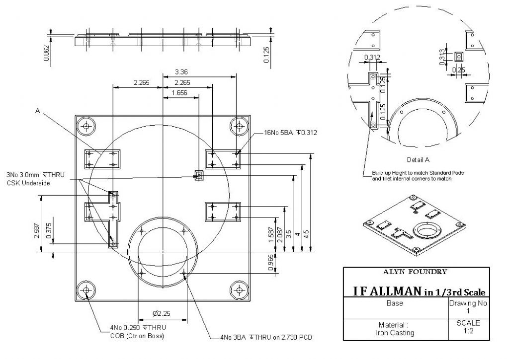
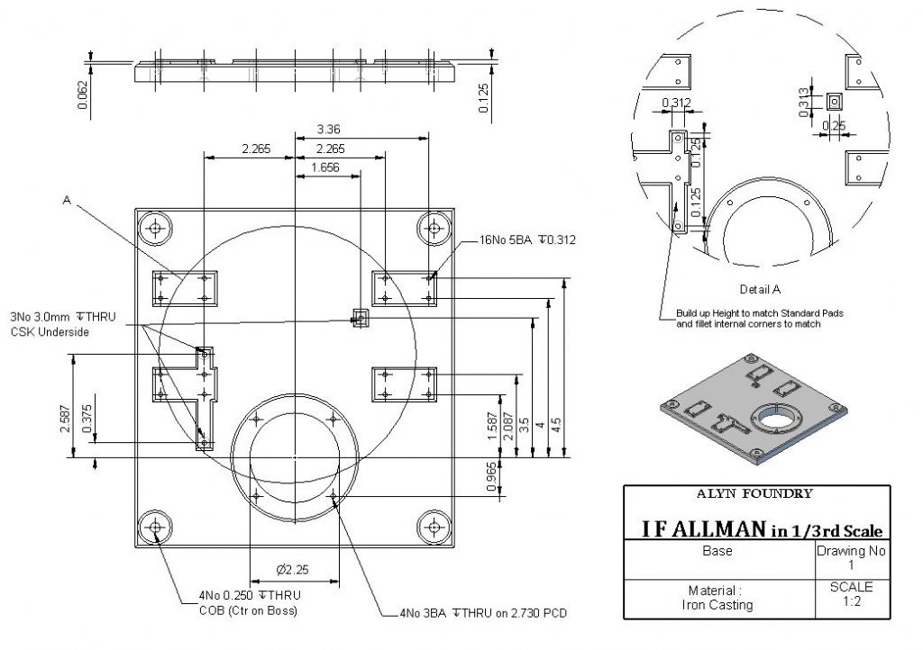
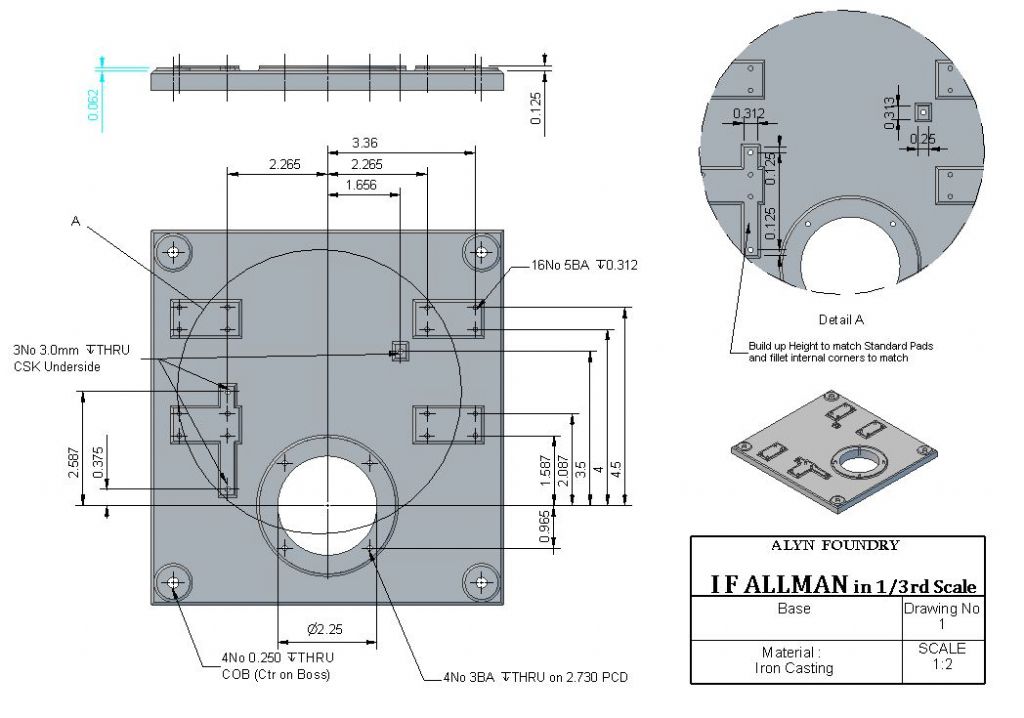
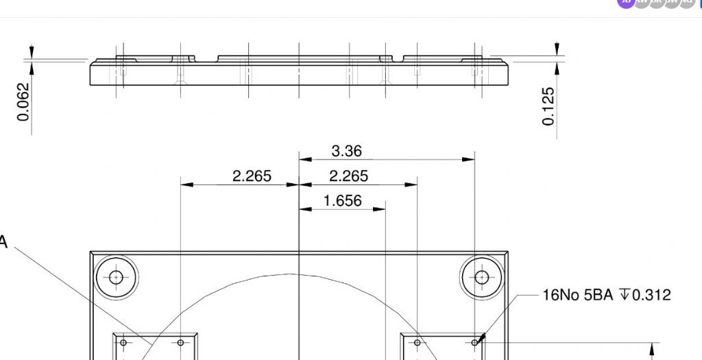
Thanks for the many replies, I won't respond to you individually but will make these comments:
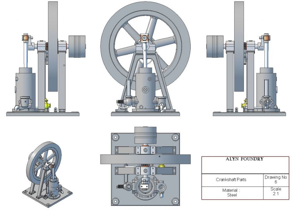
It looks like No1 is the popular choice with No2 a close second. No1 is as I said what I have used in the past so that looks like it is the way to carry on with the 2D drawings. However I think as part of the package I will do a few sheets with coloured general arrangement and some sub assemblies possibly sectioned too that can be viewed on the screen to get a feel for how things go together much like this which I have just quickly put together. May also do a fancy rendered one too which I did start on a while back. There will also be my usual 100plus build photos available.

The small isometric will stay as I think that helps visualize the part particularly on my own engine designs that have been aimed at the beginner, this particular one is for a set of castings by Alyn Foundry and I don't see many beginners making that and maybe only two others makers if no more castings are forthcoming.
I do have an A3 printer but have sized all the drawings to A4 and scaled the parts to suit as that is what the majority of people will be using to print out their set on.
They will be in PFD format as that again does not need anything special to open, view or print and the files are a reasonable size. i'm approachable to anyone who may want a part in a different format for CNC etc, don't think there is a lot in this one that would lend itself to that but some of my Series 24 from barstock designs would.
Line widths have come up in a few replies, The images posted here are just screen shots and then resized by the forum software so don't really show what the actual print looks like. main solid lines are 0.25, dimension 0.13 and hidden detail 0.13 grey scale which are standard ISO pen nib sizes so will reproduce to standard sizes if the drawing is blown up to any other A size sheet. I will change that solid "Detail A" ring to a broken line as that was bugging me too. Below is a screen shot of the PDF ( again some clarity lost) or a direct link to download for those interested here

Without getting too much into the BA -metric debate. For my own designs I am using metric throughout with the odd exception for something like BSP though I could spec that as a "G" thread  This particular engine has a lot of the cast parts that are imperial and the other ones in their range were predominantly that too so I have stuck with imperial stock and BA fixings where visible but anything out of sight is metric for example the 3 CSK holes are sized to suit socket CSK screws and on other parts I have used some metric fine where the castings have come out a bit tight for BSP for example m10 x 1 rather than 1/8" BSP.
Thank's again and keep any feedback coming.
J
Edited By JasonB on 16/01/2019 09:22:25
Tim Taylor 2.


