Universal Joint Alignment

Advert

Universal Joint Alignment

Home Forums Beginners questions Universal Joint Alignment

Viewing 14 posts - 1 through 14 (of 14 total)
  • Author
    Posts
  • #431242
    Simon Williams 3
    Participant
      @simonwilliams3

      Good evening all. and a jolly wet one it is too.

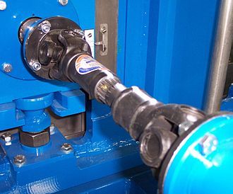
      I have been spending some time recently rebuilding a tractor, and have come to servicing the PTO shaft from the front mounted transfer box to the rear splined take off. The shaft is a simple cardan shaft with spider type universal joints at each end and a central sliding spline. The two end points run in fixed bearings and are on parallel axes.

      The yokes of the two UJ's are presently assembled at right angles on the floating centre shaft. My (limited) research suggests it is normal to align the two yokes so they are parallel, to minimise torsional vibration. OK it's a tractor and a 540 rpm shaft is hardly a precision application, but what is the logic of this?.

      Does it matter, and why?

      Looking forward to some advice, so many thanks in anticipation

      Best regards Simon

      PS (edit) Just pressed the go button and noticed the spelling mistake in the title.  Please Neil/Jason could you add the missing "r" ?  Many thanks


      Edited By Simon Williams 3 on 30/09/2019 19:45:22

      Advert
      #9878
      Simon Williams 3
      Participant
        @simonwilliams3

        Cardan Shaft assembly

        #431249
        Howard Lewis
        Participant
          @howardlewis46836

          The purpose of aligning the yokes is so that the variation in angular velocity, produced by the driving joint is cancelled out by the one at the driven end, so the driven unit sees the same angular velocities as input by the driver..

          In the Electronics and Vibration Lab, we used a single U J to calibrate torsiographs, by varying the angular displacement.

          Howard

          Edited By Howard Lewis on 30/09/2019 20:13:42

          #431269
          old mart
          Participant
            @oldmart

            I once had a car which had its prop shaft made from mismatched halves. The splines could not be aligned exactly to make the yokes parallel, it was 1/2 a spline out. I didn't notice the error until I replaced the UJ's.

            #431484
            Howard Lewis
            Participant
              @howardlewis46836

              For my birthday, our daughter gave me several years of Model Engineer, dating from 1944 to 1950.

              In the 26th December 1946 issue there is an item on universal joints. In the text it refers to fact that for the output to match the input, in terms of instantaneous speed, the forks on the ends of the intermediate shaft should be in line, so that the speed variations introduced by one joint will be cancelled out by the other. This is on the basis that the angle of the joint at each end of the shaft is the same.

              Figure 5 illustrates this arrangement.

              Howard .

              #431492
              Brian Oldford
              Participant
                @brianoldford70365
                Posted by Howard Lewis on 02/10/2019 15:42:11:

                For my birthday, our daughter gave me several years of Model Engineer, dating from 1944 to 1950.

                In the 26th December 1946 issue there is an item on universal joints. In the text it refers to fact that for the output to match the input, in terms of instantaneous speed, the forks on the ends of the intermediate shaft should be in line, so that the speed variations introduced by one joint will be cancelled out by the other. This is on the basis that the angle of the joint at each end of the shaft is the same.

                Figure 5 illustrates this arrangement.

                Howard .

                Can we see Figure 5 please.

                #431531
                Simon Williams 3
                Participant
                  @simonwilliams3

                  Hello good evening, and my thanks to all those who have taken the trouble to respond.

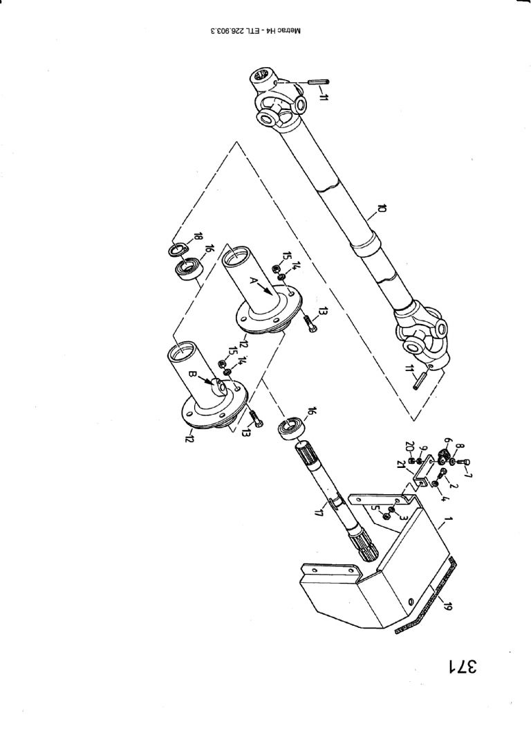
                  I've sort of got the answer I was expecting – I haven't done the maths but I would expect aligning the yoke parallel would give the best cancellation of the angular velocity variations. However here is a re-print lifted straight out of the parts list for the machine in question.

                  metrac rear pto shaft 001.jpg

                  Which clearly shows the yokes at right angles. Don't know why.

                  I've had this shaft out on a previous go-round, and I'm pretty sure its got a master spline so it will only assemble as shown. I think I'm going to have to just accept that I don't understand.

                  Many thanks once again for everyone's interest.

                  Best regards Simon

                  #431539
                  Neil Wyatt
                  Moderator
                    @neilwyatt

                    According to Wikipedia and Robert Hooke, you are all wrong and the drawing is correct:

                    " The universal joint, one of the earliest means of transmitting power between two angled shafts, was invented by Gerolamo Cardano in the 16th century. The fact that it failed to maintain constant velocity during rotation was recognized by Robert Hooke in the 17th century, who proposed the first constant velocity joint, consisting of two Cardan joints offset by 90 degrees, so as to cancel out the velocity variations. This is the "double Cardan". Many different types of constant-velocity joints have been invented since then. "

                    en.wikipedia.org/wiki/Universal_joint#Double_Cardan_shaft

                    My bold…

                    Neil

                    Edited By Neil Wyatt on 02/10/2019 21:47:22

                    #431542
                    Simon Williams 3
                    Participant
                      @simonwilliams3

                      Thank you Neil, not least for correcting my silly but very annoying spelling mistake.

                      I'm more than somewhat confused by this now – Neil you are right in quoting the link you have used, and it says what you say it says, but…

                      Along side the text is this picture, which kinda speaks for itself.

                      330px-cardan_shaft.jpg

                      There is also another paragraph later which says :

                      A double Cardan joint consists of two universal joints mounted back to back with a center yoke; the center yoke replaces the intermediate shaft. Provided that the angle between the input shaft and center yoke is equal to the angle between the center yoke and the output shaft, the second Cardan joint will cancel the velocity errors introduced by the first Cardan joint and the aligned double Cardan joint will act as a CV joint.

                      (My italics)

                      Duh!

                      x

                      #431548
                      Hopper
                      Participant
                        @hopper

                        In-line is the common automotive practice, or was when cars were rear wheel drive and you could see the U joints clearly. A google image search will confirm this.

                        You can't rely on parts drawings. They are illustrative only. And if you look at the drawing above, it has in two places the squiggly lines that indicate the the shaft has been "cut" and shortened to fit in the space available so one end could have been deliberately rotated 90 degrees for the sake of illustrating the other side of the U joint in one view.

                        And Wikipedia is written/edited by the same kind of people who post on internet forums ( laugh )so must be taken with a grain of salt.

                        This https://vibralign.com/shaft-alignment/understanding-offset-shaft-alignment/ 

                        from industry experts Vibralign is more athoritative and calls for phasing to be inline.

                        Edited By Hopper on 02/10/2019 23:56:04

                        #431557
                        Hopper
                        Participant
                          @hopper

                          PS This tech paper here **LINK**

                          might apply to your tractor PTO situation where the U joints are deliberately "phased" at 90 degrees to each other to cancel out torsional vibration due to odd angles being used at each end of the drive shaft.

                          #431587
                          Howard Lewis
                          Participant
                            @howardlewis46836

                            My vote is still for yokes in line, precisely to so that angular velocity variations caused by one joint are cancelled out by the other.

                            With Dana, Spicer and Vibralign, seems we are in good company

                            Howard

                            #431591
                            Alistair Robertson 1
                            Participant
                              @alistairrobertson1

                              A few years ago a friend who was helping a group with a tractor pulling sledge who could not get the traveling weight box to run smoothly asked for my help. I spotted that the universals on the driveshaft were not aligned and asked them to slide it out and realign on the splines. Problem solved!

                              I know that was the problem as a member of the group did not believe that was the problem and pulled the shaft off and put it back the way it was and "hey how" the problem came back!

                              Even a few degrees of input and output shaft misalignment can cause bothers and aligning the universals correctly can halve the included angle.

                              #431612
                              peak4
                              Participant
                                @peak4

                                Here's quite a good video on the subject; A some Landrover/Rangerover owners will know, depending on the model, the two flanges are sometimes not parallel. This is particularly true on the front prop only on a 110 or rangerover as the front diff is angled upwards.

                              Viewing 14 posts - 1 through 14 (of 14 total)
                              • Please log in to reply to this topic. Registering is free and easy using the links on the menu at the top of this page.

                              Advert

                              Latest Replies

                              Home Forums Beginners questions Topics

                              Viewing 25 topics - 1 through 25 (of 25 total)
                              Viewing 25 topics - 1 through 25 (of 25 total)

                              View full reply list.

                              Advert

                              Newsletter Sign-up