Unimat 3 saddle gibs

Advert

Unimat 3 saddle gibs

Home Forums Beginners questions Unimat 3 saddle gibs

Viewing 25 posts - 26 through 50 (of 57 total)
  • Author
    Posts
  • #648142
    Circlip
    Participant
      @circlip

      Don't forget, if it is GFN, the filler is GLASS. Invariably the filler is randomly oriented and glass tends to be harder than adjacent materials so scratching occurs. If not filled, the moulded faces of Nylon would exhibit better wear properties than a 'machined' surface.

      Regards Ian.

      Advert
      #648144
      Michael Gilligan
      Participant
        @michaelgilligan61133
        Posted by Circlip on 11/06/2023 09:15:58:

        Don't forget, if it is GFN, the filler is GLASS. Invariably the filler is randomly oriented and glass tends to be harder than adjacent materials so scratching occurs. If not filled, the moulded faces of Nylon would exhibit better wear properties than a 'machined' surface.

        Regards Ian.

        .

        I am always cautious about questioning your assertions, Ian … but I would like to see evidence that “Invariably the filler is randomly oriented”

        My own experience is that many such parts are made by an injection process which naturally aligns the glass rovings.

        Importantly, though: I have never seen the component in question … and would be very interested to see one sectioned and photographed.

        MichaelG.

        #648150
        Circlip
        Participant
          @circlip

          As you are no doubt aware Michael, in injection moulding, swirl is induced into the plastic so linear orientation cannot be guaranteed. Linear alignment is controlled by either extrusion with long strands or lamination of a woven matt. Problem with GRP mouldings is that if the outer surface is damaged, exposing the strand fibres, they become carriers of water along their surfaces leading to delamination. doesn't apply with GFN as the fibres are so small.

          Regards Ian.

          #648155
          Michael Gilligan
          Participant
            @michaelgilligan61133

            Happy to accept that, Ian yes

            … let’s just put it down to a difference in semantics

            MichaelG.

            #648157
            Graham Meek
            Participant
              @grahammeek88282

              The Plastic Gibs are intended to sit slightly lower than the mating face of the bedway. When tightened they are pulled down slightly, while the free end bears against the bedway. Before I machine the U3 carriage to remove wear. I checked the step between and unworn part of the carriage working face and the Gib Mounting Face. This dimension was 0.03-0.05 mm smaller than the thickness of the rear bedway.

              When I re-machined the working faces I replicated this dimension. By taking some material off the Gib mounting face. Parting off 12 mm Mild Steel on this lathe is no problem as long as the carriage clamp is on.

              Thus the first check would be to measure the gap when the Gibs are tightened in situ on the carriage and the thickness of the rear bedway. If the Gap is larger it will need attention, if it is the same or smaller, then leave well enough alone.

              A lot depends on how fine the glass fibres are chopped up. I tend to think of this material in the same way as a hand scraped surface. The high spots left by the scraping process are the the exposed glass fibres. Around these fibres small quantities of oil accumulates just as with the scraping. However given the colour of the material I would not be surprised if it was not already oil-impregnated. Thus it would be to a certain extent self lubricating.

              Are you using HSS tools or Carbide inserts?

              Regards

              Gray,

              PS was typing this as Ian's reply came in.

              #648167
              SillyOldDuffer
              Moderator
                @sillyoldduffer
                Posted by Julius Henry Marx on 10/06/2023 18:09:43:

                Hello:

                Posted by Graham Meek on 10/06/2023 17:08:58:

                … very little load on these plates, they are there just to keep the play to a minimum … | … geometry of the bedways …

                But (I still have to test it again, after adjusting the plates and see what's up) there was some perceptible movement from the perpendicular in the carriage ie: between axes X and Z.

                How can I test this properly?

                And in doing so, what lack of rigidity is acceptable or within the limits of the U3 in that respect?

                Two very good questions!

                My start with a mini-lathe didn't do well until I learned to blame TOM. That is, the need to keep an eye on the three main reasons things go wrong. They are:

                • T for tool. Plenty to go wrong on a lathe, especially one with a long history! Worn slides, bearings, screws, half-nut, and chuck. Twisted bed, bent spindles, toothless gears, set belts. Also, many opportunities for maintenance, and getting maintenance wrong – gib adjustment, noting the things go one way round and are often dimpled; blocked up oil-ways (greased when they need oil); swarf jambing the works, and adjustments: bearing preload, gear selector, and even tailstocks can be fiddly to get right. But on the whole, I think tools get more blame than they deserve, because even indifferent lathes can produce good results.
                • O is for Operator. The operator causes most of the trouble in my workshop! I'm self-taught, so lots of mistakes, painfully slow progress, and re-inventing the wheel. The list of operator errors is endless; wobbly work-holding, not locking unused axes down, not realising cutters are blunt, choosing the wrong type of cutter, getting RPM, feed-rate and or depth of cut wrong. Cutter not on centre-height, or with excessive overhang. Spinning work hitting something. Not realising work, cutters and the lathe can all bend. Pushing the machine too hard is a common beginner mistake. Hobby lathes, especially small-ones, aren't built for removing metal quickly. In the worst case a heavy handed operator will damage the motor, electronics, and drive-train. And if he gets away with that, the machine wears rapidly, and loses accuracy because it bends due to the cutter being forced into the metal. Pussy-footing is bad too – excessive caution rubs the cutting edge, blunting it quickly. Not obvious that edges last longer taking deepish cuts at a suitable feed rate – it's because optimum cuts tend to preserve the cutting edge by wedging metal off the job just in front of it. The operator has to find the sweet-spot.
                • M is for material. Many metals do not machine well. The gremlins infesting my workshop caught me out good and proper by filling my beginner junk-box with unsuitable scrap – all of it. Soft sticky Aluminium that tears. Gritty steel, tough hardened steel, work-hardening stainless, chilled cast-iron, a length of super-grabby bronze, hard brass, seamed pipe with a hard weld running down it. Thing is, quite a lot of manufacturing is done with processes other than machining. Unfortunately there's no guarantee metals selected for stamping, rolling, grinding. extrusion, casting, forging, drop-forging, welding, plating, corrosion resistance or heat-treatment will cut on a lathe. So I recommend beginners start by buying metal known to be machinable.

                Worst case is a self-taught beginner starting out with a worn or maladjusted lathe and a box full of unsuitable metal. The combination can cause a lot of problems, such as trying to part-off stainless steel held in a bell-mouthed chuck with a blunt cutter!

                So, back to first principles – what exactly are you trying to do Julius? Could be a combination of difficult material and inexperience are asking too much of the lathe. With luck the answer is easier than replacing the gibs.

                Dave

                #648173
                Julius Henry Marx
                Participant
                  @juliushenrymarx92355

                  Hello:

                  Posted by Hopper on 11/06/2023 00:41:25:

                  … non-vertical perceptible movement of the carriage on an inverted V-way bed, it is most probably down to the fit between the inverted V-way on the bed and the V-groove in the carriage.

                  Yes, I magined so. It is slight but it is there.

                  I have the feeling that the lead screw backlash does not help.

                  … small bits of swarf … | … small burrs on either surface. | … wear.

                  Everything was throroughly cleaned. As for burrs, I would have to check.

                  … by taking the carriage off and cleaning things thoroughly. | … apply a very very thin smear of engineer's blue to the bed and then rub the carriage up and down it once or twice …

                  I was planning of doing something like that but have no EB, I will try with a one of those *permanent* solvent based Sharpie markers.

                  … see from the blue spots on the carriage … | … should be fairly consistent …

                  Right. Will do that ASAP.

                  … need scraping to match, which is …

                  A really very frightening proposition. Way above my pay grade.

                  Thank you very much for your input.

                  Best,

                  JHM

                  #648176
                  Julius Henry Marx
                  Participant
                    @juliushenrymarx92355

                    Hello:

                    Posted by Kiwi Bloke on 11/06/2023 02:08:13:

                    … the mating surfaces of the underside of the saddle held the 'lift strips' a tiny bit away …

                    I will have a closer look at those surfaces.

                    I first lapped the surface of the plates on some worn 800 grade paper but then decided to turn them over. Things improved quite a bit.

                    Emco may have cut corners occasionally …

                    As I have mentioned in another post, I am an architect by trade, not an engineer. That said, the only Emco products I know first hand are the U3 and the (M1?) milling head/table, both purchased second hand roughly a year ago.

                    I am in no position to argue for or against the use of glass filled synthetics for gibs and such. But after taking apart the U3, the M1 milling head and X-T table and seeing how much effort was put into limiting the type and amount of materials used (eg: underside of the carriage (!), lead screw nut post, etc.) I am absolutely convinced that accountants and not engineers were in charge.

                    I have gone to re-read most if not all the articles/posts I poured over before deciding to purchase the U3 and not one of them mentioned that the lead screw nut was not a replaceable part. It would certainly have been a deal breaker for me.

                    But things are what they are and that is what I have to work with. With the help I am finding here at ME, I'm certain I'll be able to make the most of it.  8^)

                    Thank you very much for your input.

                    Best,

                    JHM

                    Edited By Julius Henry Marx on 11/06/2023 14:05:19

                    #648178
                    Huub
                    Participant
                      @huub

                      need scraping to match, which is …

                      A really very frightening proposition. Way above my pay grade.

                      I have "scraped" the saddle of both my lathes. For scraping I used a diamond dremel disk (not the dremel) and sanded the high spots on the saddle (not the bed) only the flat side, not the V shaped side!
                      I measured the tilt on the saddle edges using an indicator and stopped sanding when the indicator did not move when I pressed on the edges of the bed. I used the sharpy method to find the high spots.
                      After sanding with the Dremel diamond disk, I sanded the sides using a 1000 grid paper.
                      It is a time consuming but "easy" job and it will improve the rigidity and accuracy of the lathe. It is also the first thing to do before aligning these parts.

                      I did the same with the head stock and tail stock of both my lathes.

                      #648180
                      Julius Henry Marx
                      Participant
                        @juliushenrymarx92355

                        Hello:

                        Posted by Graham Meek on 11/06/2023 10:59:19:

                        Parting off 12 mm Mild Steel on this lathe is no problem as long as the carriage clamp is on.

                        I do not use a parting tool as I have not found a suitable one yet. I have seen a couple of interesting designs but have yet to decide on one. For now, I have been able to get fairly proficient at parting via the careful use of a well tesioned hacksaw with a 32 TPI blade. Locking the carriage clamp was something I discovered early on.

                        … first check would be to measure the gap when the Gibs are tightened … | … If the Gap is larger it will need attention, if it is the same or smaller, then leave well enough alone.

                        Will do.

                        Are you using HSS tools or Carbide inserts?

                        Lacking any cutting tools and wanting to get started, at first I sent for a few Carbide tools and inserts+holders. I've had mixed results with both, the new 200W DC motor being a huge improvement.

                        I am now awaiting for delivery of what I have been advised are reasonable quality 6mm HSS pre-formed tools. I expect they will do till I'm able to grind my own.

                        Thank you very much for your input.

                        Best,

                        JHM

                        Edited By Julius Henry Marx on 11/06/2023 14:24:19

                        #648189
                        Hopper
                        Participant
                          @hopper
                          Posted by Julius Henry Marx on 11/06/2023 13:28:39:

                          Hello:

                          Posted by Hopper on 11/06/2023 00:41:25:

                          .

                          … by taking the carriage off and cleaning things thoroughly. | … apply a very very thin smear of engineer's blue to the bed and then rub the carriage up and down it once or twice …

                          I was planning of doing something like that but have no EB, I will try with a one of those *permanent* solvent based Sharpie markers.

                          You need non-drying engineers blue, not drying marking blue or layout blue. Stuarts Micrometer Blue is one brand, if it is still available.

                          But if as you say in another post, you are at the stage where you have not yet learned to sharpen your own HSS tool bits, then your problems with finish are most likely due to operator technique than any problem with lift plates or V ways or other parts of the lathe and you are probably best to leave well alone for now.

                          #648196
                          Julius Henry Marx
                          Participant
                            @juliushenrymarx92355

                            Hello:

                            Posted by SillyOldDuffer on 11/06/2023 11:38:05:

                            … good questions!

                            Yes, can't ask for what is simply not there.

                            … start with a mini-lathe didn't do well until I learned to blame TOM.

                            Indeed … 8^D !!!

                            T for tool. Plenty to go wrong on a lathe, especially …

                            So I have come to learn.

                            Being mechanically oriented and confident in my manual dexterity (if you will) the first order of things for me was to take it all apart and thoroughly clean up everything, piece by piece. As you may imagine, this immediately lead to replacing the headstock bearings, the cross-slide gib, attempting to reduce the axial play in the carrier lead screw and doing something about the hand-wheels, tasks which are for the most part finished.

                            … tools get more blame than they deserve … | … even indifferent lathes can produce good results.

                            Indeed, but in the hands of an experienced machinist.

                            … operator causes most of the trouble …

                            Yes. In another life I worked a few years in IT and PICNIC (problem in chair not computer) was the culprit over 80% of the time.

                            … self-taught, so lots of mistakes, painfully slow progress, and re-inventing the wheel.

                            I can fully relate to that.

                            … list of operator errors … … wobbly work-holding … | … not locking unused axes … | … not realising cutters are blunt … | … choosing the wrong type of cutter … | … RPM, feed-rate and or depth of cut wrong … | … not on centre-height … | … excessive overhang …

                            Yes, guilty on all counts.

                            Spinning work hitting something. Not realising work, cutters and the lathe can all bend. Pushing the machine too hard …

                            These last ones are the worst ones as the damage they can cause can be important.

                            Also guilty.

                            … especially small-ones, aren't built for … | … The operator has to find the sweet-spot.

                            Quite so.

                            I am slowly but steadily finding my footing. As in most things in life, experience is paramount but something to be acquired as transmisison is always difficult, sometimes impossible. And then, many times, only the hard way.

                            … gremlins infesting my workshop caught me out good and proper by filling my beginner junk-box with unsuitable scrap – all of it.

                            Same here. I am an avid skip-diver as I loathe seeing what seems recoverable/reciclable materials get discarded. I have recovered a great many things which have saved me both time and money many times.
                            To wit: my self-made, gas fired coffee roaster was made using over 75% recycled/skip recovered parts and materials.
                             
                            With respect to metal for use on the U3, I have been able to spot the worst. It is the borderline stuff that will get me into trouble.

                            eg: I can properly identify most unusable stuff such as soft sticky Al, seamed pipe or metals that look / feel as they cannot be used. But I have work-hardened steel. Lack of proper training and dull / inapropiate tools have played an important part.

                            But I have had good luck with a piece of SAE68 bronze I am using in an attempt to machine a new led screw nut for the cross-slide which has an incredible amount of wear.

                            … self-taught beginner starting out with a worn or maladjusted lathe …

                            Can't help being self-taught, time and patience will fix that but I am slowly making progress fixing a worn lathe with adjustment problems. Eventually, I guess.

                            See next post …

                            Edited By Julius Henry Marx on 11/06/2023 16:09:42

                            #648198
                            Julius Henry Marx
                            Participant
                              @juliushenrymarx92355

                              … continuation:

                              … what exactly are you trying to do Julius?

                              At the moment I am in the process of turning a new lead screw nut for the U3's cross slide from a 25mm piece of 100mm long SAE68 (?) bronze stock. Rather sloppy in its manufacture (uneven surface+a bubble taking up about 7.0mm of the total length) but an unbeatable price.

                              Adjusting the lift plates has made quite a difference. If I can manage to get this part done and working properly, another problem will have been solved.

                              Next in line are carrier lead screw wear which I seem to have (partly/temporarily) solved with the contraption below and headstock / tailstock alignment which I think is a can with a great many worms in it.

                              contraption.jpg

                              … a combination of difficult material and inexperience …

                              Undoubtedly so, I'll try my best to deal with it. I have been in worse situations before. 8^)

                              Thank you very much for taking the time to write up such an interesting and thoughtful post in answer to my questions.

                              It clearly and very accurately reflects my personal experience with the use of the U3.

                              In my opinion, it should be a 'sticky' at the very start of the 'Beginner's questions' section of ME and labeled as mandatory reading for any beginner, especially if they are owners of a Unimat 3 or similar.

                              Best regards,

                              JHM

                              Edited By Julius Henry Marx on 11/06/2023 16:28:39

                              #648200
                              Julius Henry Marx
                              Participant
                                @juliushenrymarx92355

                                Hello:

                                Posted by Hopper on 11/06/2023 15:31:25:

                                … non-drying engineers blue, not drying marking blue or layout blue. Stuarts Micrometer Blue is one brand, if it is still available.

                                I don't think that is available locally.

                                Is there any other type of ink/marking liquid it can be substituted with?

                                … at the stage where you have not yet learned to sharpen your own HSS tool bits, then your problems with finish are most likely due to operator technique …

                                I'm sure of it and I'll keep it in mind. Won't be mucking around just because.

                                Thanks for your input.

                                Best,

                                JHM

                                #648212
                                Huub
                                Participant
                                  @huub
                                  Posted by Julius Henry Marx on 11/06/2023 16:23:47:

                                  Is there any other type of ink/marking liquid it can be substituted with?

                                  The paint should not dry so quickly. You can use an "art painters oil based paint" that is available in small quantities. Any dark (Blue, Red, BLack) colour will do.

                                  #648215
                                  Julius Henry Marx
                                  Participant
                                    @juliushenrymarx92355

                                    Hello:

                                    Posted by Huub on 11/06/2023 18:19:20:

                                    … paint should not dry so quickly. … an "art painters oil based paint" …

                                    Thanks for that, I've read that it is prussian blue mixed with grease.

                                    I'll see what I can find and try.

                                    Best,

                                    JHM

                                    #648218
                                    old mart
                                    Participant
                                      @oldmart

                                      We have just made a brass gib for the longer cross slide on the Atlas 12 x 24 lathe, it was the best size laying about and quite good. The original looks like cast iron, and if I had a choice some bronze woulf have been used. The aluminium might wear faster, but if it is available and can be adjusted easily, I see no reason not to use it. Keep the bed clean and oiled and all should be well.

                                      #648230
                                      Julius Henry Marx
                                      Participant
                                        @juliushenrymarx92355

                                        Hello:

                                        Posted by Huub on 11/06/2023 14:12:37:

                                        … "scraped" the saddle of both my lathes. | … diamond dremel disk … | … sanded the high spots on the saddle (not the bed) only the flat side, not the V shaped side!

                                        You sir are undoubtedly both a brave (and knowledgeable) soul! 8^D

                                        … measured the tilt on the saddle edges using an indicator and stopped sanding when the indicator did not move when I pressed on the edges of the bed. I used the sharpy method to find the high spots.

                                        Interesting. (warnings have been taken into account …)

                                        After sanding with the Dremel diamond disk, I sanded the sides using a 1000 grid paper.

                                        Am I correct in assuming you are measuring the 'tilt' from/between front to/and back?

                                        I think that is the hardest part to get right.

                                        Could the milling column vee block (on the back of the bed) be used for the magnetic base?

                                        … time consuming but "easy" job and it will improve the rigidity and accuracy of the lathe. It is also the first thing to do before aligning these parts.I did the same with the head stock and tail stock of both my lathes.

                                        When I am through with all the pending stuff I will have a go at the measuring part of the procedure to see exactly what is going on.

                                        Not having a reliable idea of the situation is a sure recipe for going around in circles.

                                        Thank you very much for your input.

                                        Best,

                                        JHM

                                        #648241
                                        Huub
                                        Participant
                                          @huub
                                          Posted by Julius Henry Marx on 11/06/2023 20:55:20:

                                          After sanding with the Dremel diamond disk, I sanded the sides using a 1000 grid paper.

                                          Am I correct in assuming you are measuring the 'tilt' from/between front to/and back?

                                          You can measure the tilt using an indicator but you probably feel the headstock/saddle/tail stock rocking when pressing on one of the four corners. Weep off any oil because that influences the measurement.

                                          You have to check the tilt of the headstock at its mounting position.
                                          You can check the tilt of the saddle/tail stock on any position of the bed. I used the end of the bed because that is worn the least.

                                          I think that is the hardest part to get right..

                                          The hardest part to get right is the head stock alignment. Once the head stock isn't rocking any more, you can adjust the alignment. For that you have to remove metal on two places so the headstock doesn't start rocking again.
                                          For changing the up/down angle, you have to remove metal on the front or the back (flat side and both sides of the V).
                                          For changing the left/right angle, you have to remove metal on 2 opposite sides of the V.

                                          Because you don't remove much metal, It is a slow process so it takes a lot of trials to see a change in the alignment. That also means that if you remove the metal on the wrong side, you only slowly increase the error.
                                          You need to keep the test bar in the head stock/chuck for checking the alignment. That makes the head stock quite heavy.
                                          I used a self made test bar because this test bar has no runout and that makes checking the alignment easier.

                                          Once the headstock is aligned, you can align the tail stock.
                                          Some lathes have a headstock that allows changing the left/right angle by rotating the head stock around a swivel point.

                                          If you bolt your lathe to a rigid stand, you can twist the lathe bed causing mis alignment. So my mini lathe and bigger lathe are not bolted to the stand.
                                          The rigidity of my bigger lathe would surely benefit from bolting to the stand but the concrete floor would influence the lathe alignment when the temperature changes (summer/winter) and that is a no-go for me. My shop is on the first floor (pre tensioned concrete plates)!

                                          #648252
                                          Hopper
                                          Participant
                                            @hopper
                                            Posted by Huub on 11/06/2023 21:56:13:

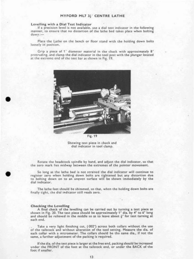
                                            If you bolt your lathe to a rigid stand, you can twist the lathe bed causing mis alignment.

                                            Not if you do it correctly and put shims under any of the lathe feet that are not in contact with the base before tightening down any of the bolts. Here is a description from the Myford manual on how to do it, and how to use a dial indicator to make sure there is zero distortion of the bed when bolting it down. See Fig 19 and text below that.

                                            myford manual 1.jpg

                                            #648560
                                            Julius Henry Marx
                                            Participant
                                              @juliushenrymarx92355

                                              Hello:

                                              Posted by Kiwi Bloke on 11/06/2023 02:08:13:

                                              … the mating surfaces of the underside of the saddle held the 'lift strips' a tiny bit away …


                                              I think that the original topic ie: question about lift plate material has been answered and it would be a good idea to split this post to another, related and equally important topic.

                                              I went to my usual purveyor of plastics and non-ferrous materials today and got a very good deal on a few left over bits and pieces, one of which was a length of 5/8" x 5/32" brass, more than enough to make myself a new pair of lift plates to replace the ca. 1980 Emco issued ones.

                                              Then I started on Kiwi Bloke's suggestion which I think merits its own thread.

                                              Thank you all for your input.

                                              Best,

                                              JHM

                                              Edited By Julius Henry Marx on 15/06/2023 02:50:36

                                              Edited By Julius Henry Marx on 15/06/2023 04:14:02

                                              #648581
                                              Hopper
                                              Participant
                                                @hopper

                                                Fitting of the strips seems related to the choice of material. Bit of brass should work for you. I vaguely remember on one "microlathe" I fixed up for a bloke a few years ago it did perform better when we set up the lift plate strips (steel from memory) so they were a neat sliding fit on the underside of the way where they run. Blued them up to just contact and that is all. Had to rub a few high spots down on the ways with a fine flat file and rubbing stone. In theory the lift plate should not affect cutting but in practice it did seem to help on these rigidity-challenged tiddlers.

                                                Edited By Hopper on 15/06/2023 08:40:53

                                                #648588
                                                Michael Gilligan
                                                Participant
                                                  @michaelgilligan61133
                                                  Posted by Hopper on 15/06/2023 08:40:29:

                                                  […]

                                                  In theory the lift plate should not affect cutting but in practice it did seem to help on these rigidity-challenged tiddlers.

                                                  .

                                                  I suspect that the lack of mass in the saddle and its attachments might be a major contributor to the problem … a big lathe has lots of inertia there, and the saddle is well-behaved on the inverted vees.

                                                  dont know Could we be in one of those “you can’t scale Nature” situations, I wonder ?

                                                  MichaelG.

                                                  #648597
                                                  Graham Meek
                                                  Participant
                                                    @grahammeek88282

                                                    The OP says he uses Carbide inserts. There is no problem with this provided the insert radius is not too big. I only use 0.2 mm radius inserts on my Unimat. Using a 0.4 mm rad causes a lot of vibration and a poor finish.

                                                    The Compact 5 will tolerate the 0.4 mm radius with no problem. Having said that there is more contact area on the carriage. Plus the headstock bearings and spindle are more robust. It is all a question of rigidity with these small machines. The quality of the insert is another key player. They will seldom have as keen an edge as an HSS tool properly stoned.

                                                    The Unimat machine was designed in the early 1970's and it was designed around HSS tools. This was the tooling that Emco originally supplied. Emco did not start supplying Carbide inserts for the C5 until the 1990's.

                                                    Regards

                                                    Gray,

                                                    #648609
                                                    Julius Henry Marx
                                                    Participant
                                                      @juliushenrymarx92355

                                                      Hello:

                                                      Posted by Hopper on 15/06/2023 08:40:29:

                                                      … seems related to the choice of material.

                                                      I believe so.

                                                      Having read more than one post on various forums where it was stated that the change to brass strips made a noticeable difference, I look forward to being able to say the same thing.

                                                      Posted by Michael Gilligan on 15/06/2023 10:41:14:

                                                      … lack of mass in the saddle and its attachments might be a major contributor …

                                                      No suspicion whatsoever on my behalf: I'm absolutely convinced that it is the major contributor.

                                                      Just the fact that a barely ill fitting set of lift strips will wreak havok to the simplest turning operation (eg: small diameter, short piece of plain aluminium) attests to that being so.

                                                      Like I mentioned earlier in this same thread: " … how much effort was put into limiting the type and amount of materials used (eg: underside of the carriage (!), lead screw nut post, etc.) I am absolutely convinced that accountants and not engineers were in charge."

                                                      … one of those “you can’t scale Nature” situations …

                                                      If it were only that (ie: scale) then the U3 would have a saddle cast from the same material as the bed and it would have a size/weigh/heft in proportion to the size/weight/heft of the bed, like most lathes seem to have.

                                                      Thank you both for your input.

                                                      Best,

                                                      JHM

                                                      Edited By Julius Henry Marx on 15/06/2023 12:28:24

                                                    Viewing 25 posts - 26 through 50 (of 57 total)
                                                    • Please log in to reply to this topic. Registering is free and easy using the links on the menu at the top of this page.

                                                    Advert

                                                    Latest Replies

                                                    Home Forums Beginners questions Topics

                                                    Viewing 25 topics - 1 through 25 (of 25 total)
                                                    Viewing 25 topics - 1 through 25 (of 25 total)

                                                    View full reply list.

                                                    Advert

                                                    Newsletter Sign-up