With the Sun shining into the workshop I was able to take a couple of photographs
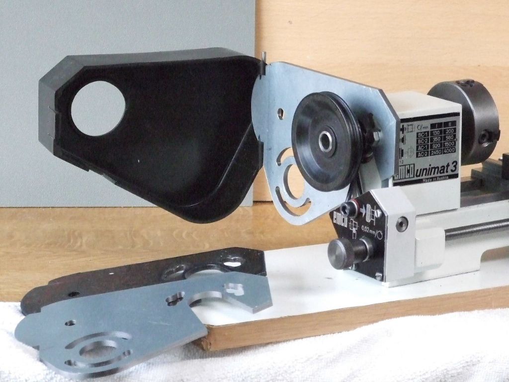
The shot above shows the old and new parts together prior to fitting onto the lathe.
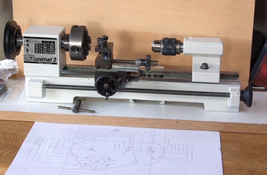
Now it is beginning to look more like a lathe. The drawing in the foreground is the project for this week.
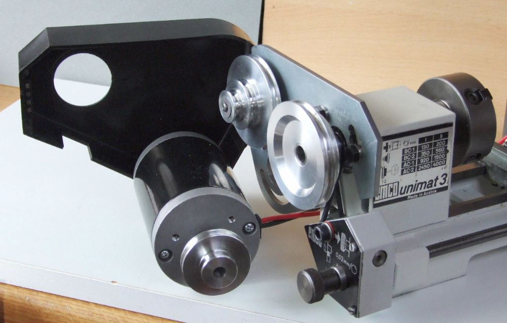
When received the lathe came with a GEC 1/8 HP Induction motor, which was full of Brass swarf. The motor weighs more than the lathe and the original Motor mounting plate had been severely chopped about. While the motor fitted in its allotted place the overhanging weight attached to the Headstock was not considered a good idea.
Hence the new DC drive is more compact, less weight and is more powerful.
This last week saw the pair of new backplates finished. The new spindles for the idler pulleys were finished this morning after the photo-shoot.
I did have some good fortune midweek in that the missing Power feed housing turned up. My lathe donor had finished cleaning out his shed and came across this part. The euphoria was short lived however when I discovered one of the previous owners had taken a twist drill to the Wormwheel bore. Why they had done this is beyond me and it is probably the reason why I had all the other parts. The hole left after the drilling was anything but round, and off centre. Luckily there was about 6 mm of the original 8 mm bore remaining. This allowed me to clock this to get onto the original centre.
The hole was then bored out to 9.5 mm and a Phos Bronze bush made to salvage the unit.
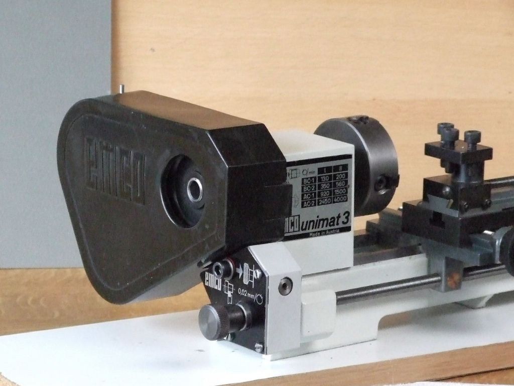
Lastly the cover in-situ to make sure everything fits as it should.
This week I hope to get a start made on the mounting board and the Motor pulleys.
Progress on the restoration has slowed over recent weeks. Mainly due to the effects of my booster jab on my illness.
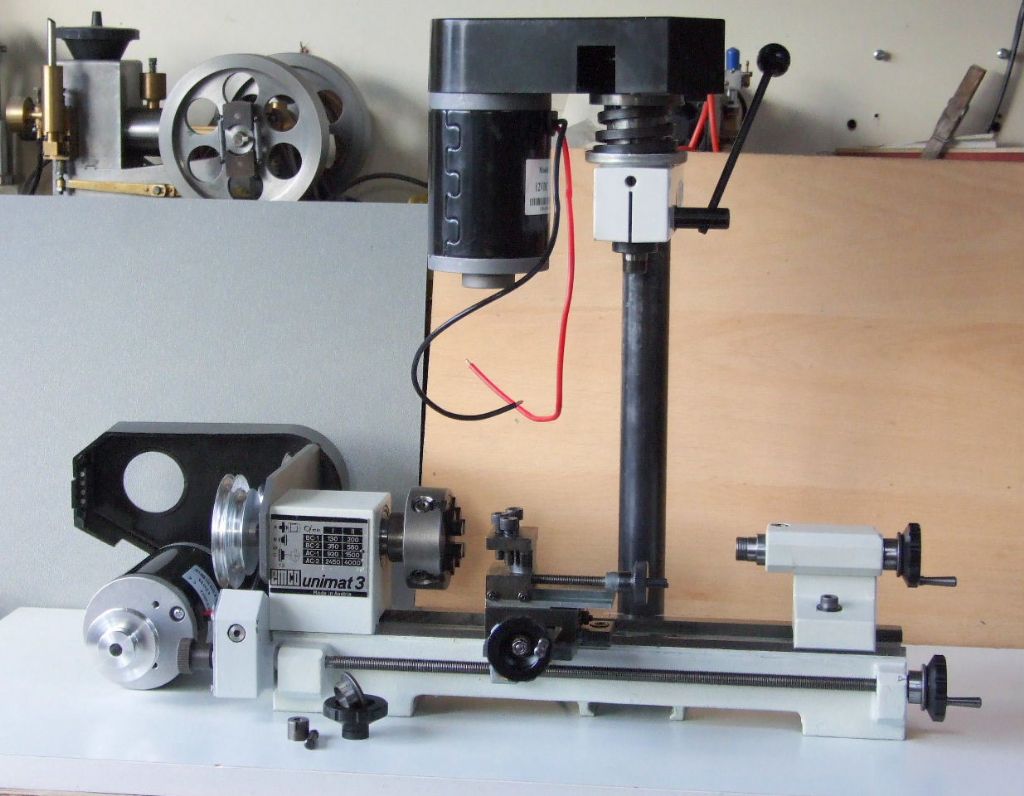
Father Christmas did get his dates mixed up however in that I had an early Christmas present from my Daughter in the form of the Milling attachment for the the Unimat.
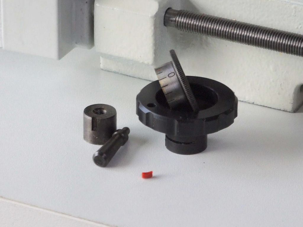
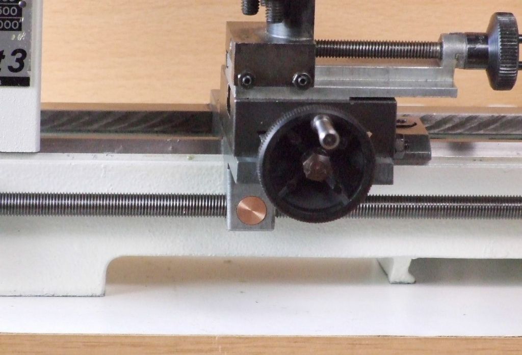
You will see from the above Photograph that the lathe is now sporting some new Handwheels, which have been made in-house with adjustable dials.
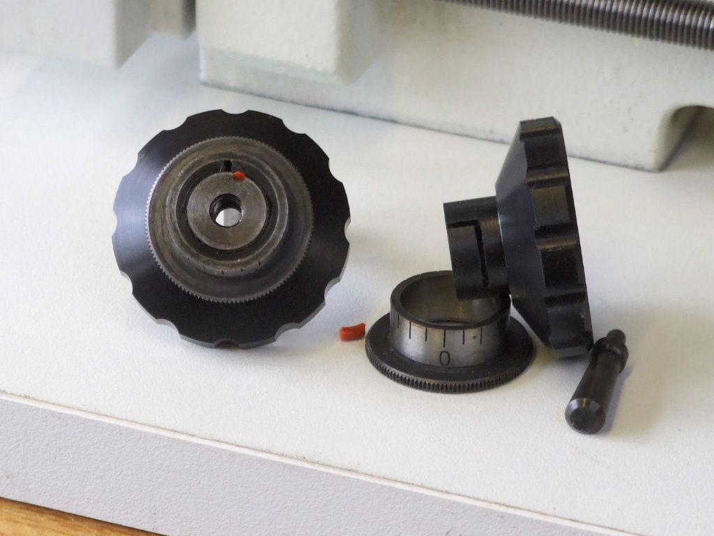
I wanted to keep the Black Handwheel theme going, so the main part of the handwheel was made from Delrin. The small piece of Silicone O-ring acts as a spring to provide friction on the dial by displacing the Delrin ear on the handwheel.
The ear can be seen more clearly in this shot, as well as where the small piece of silicone goes.
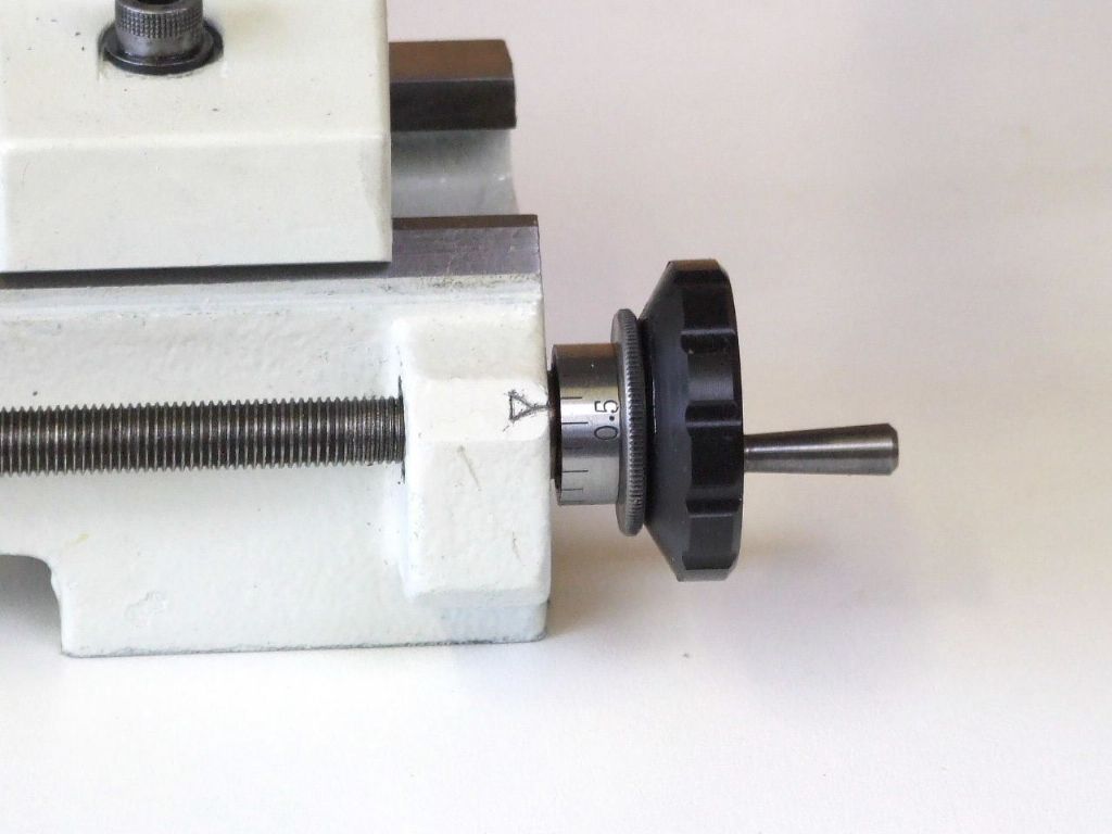
This shows the dial in-situ on the longitudinal feed, or leadscrew.
Originally I made one new Idler pulley for the Milling attachment and two motor pulleys, but yesterday I noticed the original plastic mandrel pulley was running out by a mile. When received this lathe was fitted with some vacuum cleaner drive belts. These had been on the machine for sometime while in storage and had given the pulley a permanent set. A new aluminium pulley was duly made.
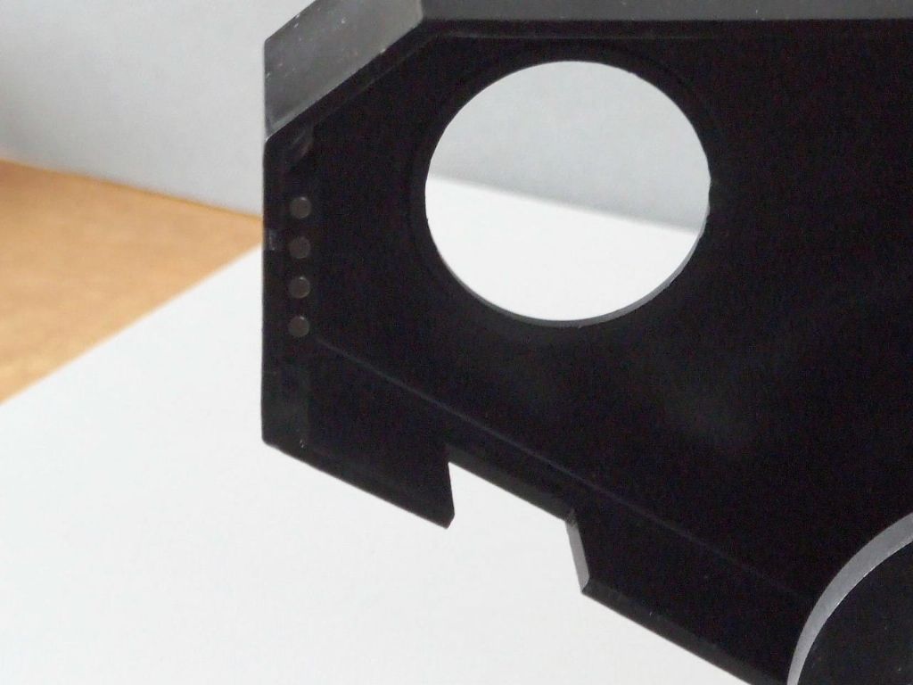
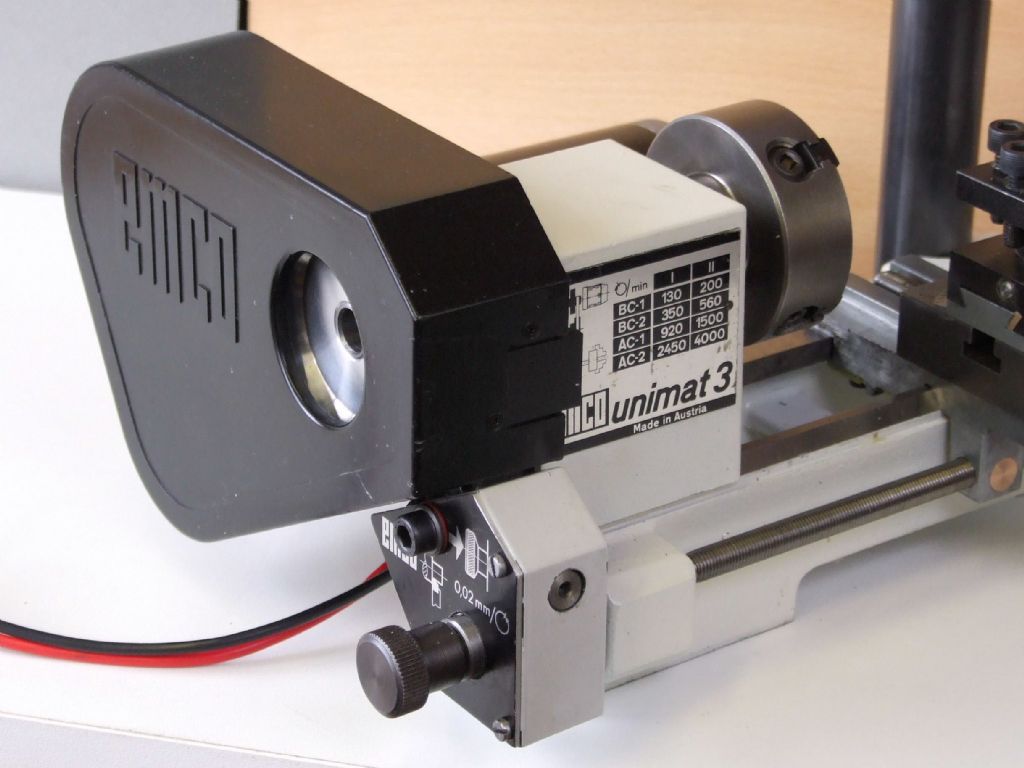
The original integral catches on each guard had been broken at some stage. A piece of Delrin was machined to fit the vacant space and four small magnets were pressed in to keep the guard closed in use.
I tried to mimic the original catch as best I could. The small protrusion makes getting the guard open very easy. The replacement piece is held in lace by two small self tapping screws.
My next task is to make the base board to house the electrics for the motors.
Following a period of post-Op recovery I have at long last been able to take some photographs of what has been happening in the workshop.
Apart from a coat or two of varnish on the woodwork this project is complete. I am very pleased with the outcome. The machine is much quieter than I remember the Unimat to be with its AC Motor.
There is an added bonus in that the lathe toolholders for my Compact 5 will fit directly into the topslide toolpost without any alteration to centre height.
I have been putting the lathe to use today on some bearings for my Compact 5 screwcutting clutch. I am really pleased with the smoothness and quietness of this machine. It has been well worth the effort, plus I saved it from the skip
Have you sent photos of the finished item and its cabinet to Emco? I think they'd very happy to see it given a new lease of life.
I hope it inspires me to achieve something towards that quality when I come to restore my always-loved but well-worn EW lathe.
That presently has a modern motor, but still like its predecessor, a 230V AC one. Your comments about treating your Emco to D.C. drive makes me think that route for my machine.
Alas Emco have moved on from the Hobby machines, having amalgamated with a much larger concern. They are more industrially based these days. This to me is a pity as they gave the Hobby many innovations over the years, which have been copied around the world.
I have been using the U3 today to put the finishing touches to my Proxxon Milling machine table feed attachment.
I have had several PM's over recent months for details on the above modification. I have written up some notes for anyone else who is considering this salvage scheme.
"This repair is not an easy task and it needs to be approached methodically. The only safe surfaces to come off are the cross-slide flat ways. As the Lug portion the leadscrew passes through is tapered on all four sides.
Using parallels the cross-slide faces are bolted to a small angle plate. By using a couple of dowels about 5 mm diameter in the dovetail vee the carriage assembly is clocked parallel to the edge of the angle plate. The dovetail ways of the cross-slide now being vertical to the surface plate and the bottom "working face" of the angle plate. (Lug needs to be uppermost)
In a vertical type mill bolt the angle plate to the machine table. With a close fitting "turned spigot" in the existing leadscrew tapped hole and using an edge finder locate the leadscrew centre-line, parallel to the angle-plate vertical face. Once on this centre-line and using a Verdict type clock. Clock either side of the casting Lug to bring the leadscrew lug central under the machine spindle.
From memory the thickness of the casting at this point is 15 mm. A 10 mm drilled, bored and reamed hole is then machined in the casting.
Re-clamping the angle-plate such that the leadscrew centre-line is now running vertically. Using the turned spigot again, clock to get the leadscrew and spindle centre-lines concentric. Open up the existing tapped hole using an 8 mm end mill, followed by an 8.1 or 8.2 mm drill. Nothing bigger as there is not much meat about here.
It is best to rough out the PB nut, tap the 8 mm LH thread and then finish machine the outside diameter to size, (9.99 mm for a reamed hole). Tapping PB throws up awful burrs and distortion on the diameter, hence why I used this method. It goes without saying that the tapped hole has to be on the centre-line of the 10 mm diameter, so some careful machining is required on this part"
I have had a request for the backplate drawing shown earlier in this post. This is the Emco standard backplate which the Far Eastern E-Bike motor fits easily, without any modification.
What did you use for your motor controller? I went down the replacement motor/controller route a couple of years ago but the controller has never been at all satisfactory, although I never seem to have found time to investigate a replacement.
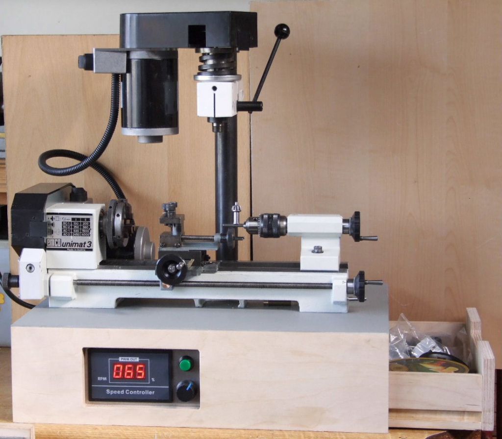
I used a PWM unit from Amazon, it is shown in one of the earlier photographs. The Power Supply also came from the same source and is a fan cooled unit rated at 12v DC 30amp.
Although the Controller display says RPM it is actually a %. I tend to use 43 and 65% using these two settings mimics the old U3 two speed motor. As I prefer to use the old belt settings to vary the speeds.
This system works for me but it may not be everyone “Cup of Tea”. There is an advantage in that this set-up is far quieter than the old U3 motor and I much prefer this. One thing to watch out for is the Spindle does stop rather quickly when the power is switched off. Almost as if there is a DC brake fitted to the spindle.