Unimat 3 carrier rigidity problem

Advert

Unimat 3 carrier rigidity problem

Home Forums Beginners questions Unimat 3 carrier rigidity problem

Viewing 12 posts - 26 through 37 (of 37 total)
  • Author
    Posts
  • #649173
    Michael Gilligan
    Participant
      @michaelgilligan61133

      I see your point, Kiwi Bloke

      1. If the saddle was sufficiently heavy, then [with a prismatic bed] there would be no need for the strips.
      2. Given that we can’t scale nature, [1] is not feasible in practice.
      3. The original strips act as springs … thus substituting for the missing weight.
      4. Comparatively very stiff metal plates, firmly bolted, turn the system into a linear bearing which does not rely upon Gravity for its operation.
      5. For [4] to work … everything would need to be made/fitted/maintained to appropriate tolerances !

      MichaelG.

      Advert
      #649176
      Hopper
      Participant
        @hopper

        The way Myford and many other lathes do it is have shim strips between the lift plate and the saddle casting. You peel off layers of shim, or fit thinner shims, until the desired clearance/contact is achieved. This has the advantge of keeping the whole lift plate parallel to the bed surface it bears on, resulting in contact over the full surface rather than the line contact of the tilted lift plates.

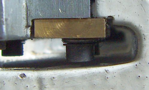
        But some of the small Chinese lathes use the above pictured system with the canted plates adjusted by two grub screws and held down by two other screws.

        #649179
        Kiwi Bloke
        Participant
          @kiwibloke62605

          Hooray! Michael's got it! Far more succinct than my rambling…

          Apologies to Monsieur Belleville for mis-spelling his name (the shame…).

          #649181
          JasonB
          Moderator
            @jasonb

            I wonder if a single plate relieved to clear the central rib would work better? You could have the jacking grub screws without the chance of single plates tipping and/or use some form of springs to apply a constant pressure.

            #649184
            Graham Meek
            Participant
              @grahammeek88282
              Posted by Michael Gilligan on 21/06/2023 07:37:09:

              I see your point, Kiwi Bloke

              1. If the saddle was sufficiently heavy, then [with a prismatic bed] there would be no need for the strips.
              2. Given that we can’t scale nature, [1] is not feasible in practice.
              3. The original strips act as springs … thus substituting for the missing weight.
              4. Comparatively very stiff metal plates, firmly bolted, turn the system into a linear bearing which does not rely upon Gravity for its operation.
              5. For [4] to work … everything would need to be made/fitted/maintained to appropriate tolerances !

              MichaelG.

              Hi Michael,

              You have captured in a nut shell the design criteria associated with the Emco Gib arrangement.

              Regards

              Gray,

              Generally

              Like Kiwi Bloke I think the current tipped Gib arrangement will need constant adjustment. Line contacts wear rapidly. If one takes a moment to consider the set-up which is shown in the above photograph. The only part in contact with the underside face of the Bed is the outer edge of the Brass Gib. I also fail to see how this arrangement is superior to a Gib which is firmly bolted down. As opposed to something which is standing on Stilts.

              Perhaps this is why there been so many designs to improve this Gib set-up over the years.

              The plastic Gibs of my Unimat show a distinct wear patch adjacent the hold down bolts which is in contact with the bedway face. This patch extends across the whole width of the contact face.

              From what I can see in the above photographs there appears to be a ridge on the Vee-way which indicates excessive wear. Something I highlighted in the other post on this topic when I suggested "lifting" the Carriage to check for vertical play.

              Regards

              Gray,

              #649201
              Julius Henry Marx
              Participant
                @juliushenrymarx92355

                Hello:

                Posted by Kiwi Bloke on 21/06/2023 07:13:26:

                … confused? So am I…).

                I'm sorry about that. I should have asked the moderator for instructions …

                … Sieg approach looks attractive at first sight …

                Yes, it looks like it works but I cannot say for sure. To me, it makes sense and it should work but just how well I could not say, never seen a Sieg C0 (now apparently discontinued) myself though I have read quite a few negative opinions about it. In contrast, have read quite a few glowing opinions about the Unimat 3. 8^)

                Thanks for your input and sorry for the confusion caused.

                Best,

                JHM

                #649210
                Julius Henry Marx
                Participant
                  @juliushenrymarx92355

                  Hello:

                  Posted by Kiwi Bloke on 21/06/2023 07:30:02:

                  … replying to your post above.

                  Interesting approach. No doubt your approach will work fine. Whether it will continue to do so as it wears remains to be seen. Realistically, it isn't going to wear much is it?

                  Yes, I thought about it for hours while attempting to imagine just how it would work, if it would work, how much of the contact surface would be lost with the tilt, how much is would wear and at what rate, if it would need more lubrication, etc.

                  After making a pile of small sketches I settled on the ideas I am putting down below, obviously to be proven (or not) after some sustained use. Taking into account that I am not at the U3 six hours a day, that could mean a relatively long time.

                  1. … will tend to cause line contact … | … associated with greater wear.

                  I would be surprised if the wear over (say, 12 months) were to be significant enough to matter. ie: to create a situation where the carriage will act up and affect when turning a piece. The original strips showed wear along a ~3 mm band so checking the state of the brass strips in a couple of months should give us a rough idea / approximation.

                  As mentioned, the photograph showing how this arrangement works is an extreme to illustrate the idea.

                  In reality, when the strips are held in place by the mounting screws they are practically touching the ways before the set screws are turned. As mentioned, the set screws are M4x0.7 and I achieved what I considered to be right adjustment ie: smooth movement of the carriage without discernible lifting or jamming of the strips, with just a touch of the screw.

                  Just a touch (whatever quantity that effectively is) in this case means a very slight turn of the set screw. Given the pitch, this translates into a very small advance and as a result, a very slight lift of the trailing edge of the strip. ie: practically no pressure between the way and the strip and I assume (here's the scale factor again) a very small angle between both.

                  I expect that as time goes by, the leading edge of the strip will indeed suffer some wear but as this happens, the contact surface will be progressively increased.

                  Will have to check and see just how much further on.

                  2. You could use Belville washers (or other spring washers) under the retaining screw heads to achieve preload. (IIRC, Emco use wavy spring washers).

                  Yes, the first thing that came to mind when you mentioned pre-load was the use of some sort of spring washer to replace the existing flat ones but have not come up with anything yet. All I have found are grover type washers (split) but I am not sure if they will work properly in this case.

                  3. … not float on a film of oil … | … There will be metal-to-metal contact.

                  Please excuse my being so optimistic, ie: ignorant. 8^) Slides would probably have been a more accurate term to use.

                  4. Don't lose sleep over it. "She'll be right" …

                  Indeed … But I enjoy the challenge and in turn, learn something new.

                  The whole thing is working much better now. A day/night difference with respect to what I was going through when I started the post on the material to use for the gibs.

                  Thank you very much for your input.

                  Best,

                  JHM

                  #649213
                  Julius Henry Marx
                  Participant
                    @juliushenrymarx92355

                    Hello:

                    Posted by JasonB on 21/06/2023 10:28:51:

                    … a single plate relieved to clear the central rib would work better?

                    Interesting idea.

                    … jacking grub screws without the chance of single plates tipping and/or use some form of springs to apply a constant pressure.

                    The first thing that comes to mind is that, given the height of the central rib, a single plate would have to be much thicker, maybe as much as ~10 mm. and there may not be enough room.

                    Thanks for your input.

                    Best,

                    JHM

                    #649237
                    Julius Henry Marx
                    Participant
                      @juliushenrymarx92355

                      Hello:

                      Posted by Julius Henry Marx on 21/06/2023 14:43:41:

                      … translates into a very small advance and as a result … | … a very small angle between both.

                      While I was writing my reply to your post, I had in mind mentioning this but eventually forgot. 8^°

                      It could happen that the tilt angle ends up being more than acceptable and cause equaly unacceptable edge wear on the strips. After all, this is an experiment, a work in progress.

                      But I think it can be easily solved by simply repeating the previous operation on the surfaces that the plates sit on. ie: removing a bit more material.

                      The optimium situation being that the surface coincides with the surface of the way so that the needed tilt is close to nothing.

                      I may eventually have a go at it and see if this arrangement can be improved but first I'd like to see what wear the strips show after a bit of carriage travel.

                      Best,

                      JHM

                      #653405
                      Julius Henry Marx
                      Participant
                        @juliushenrymarx92355

                        Hello:

                        Posted by Julius Henry Marx on 21/06/2023 16:51:00:

                        … see if this arrangement can be improved …

                        An update:

                        After a fortnight or so I had to dismantle the carrier again to take some measurements and had a look at the new brass gibs. I then realised that they needed a tad more removal from the surface they are bolted on to, so went about doing that.

                        It was not a case of line wearing as the width of the markings on the brass were quite consistent with the markings I had measured on the OEM lift strips but as the use of the set screws was needed, I decided to go ahead and see what I could do.

                        It was a very small amount and the result was quite satisfactory, to the extent on not needing any adjustment from the Sieg C0 type set screws I had added.

                        But then I found out that the whole arrangement had become more difficult tighten, I guess due to the smaller dimensions at play and the 0.7 pitch of the mounting screws.

                        The solution (again) was to follow Kiwi Bloke's advise and use Bellville washers, so I added a pair arranged in series (on top of the OEM washer) to each screw.

                        The carrier now moves very smoothly and, as expected, gets tighter as it reaches each end of the bed.

                        I expect that, as the gibs wear the carrier will loosen up and then it will become necessary to use the set screws to adjust the gibs accordingly but I think it will take many hour's use of the U3 for that to happen.

                        Here's a photo of the gib below the flat as seen from the tailstock end, with the Bellville washers clearly visible:

                        gibs_belville_2.jpg

                        It looks like it is as Kiwi Bloke said: She'll be right.
                        That's about it for now.

                        Best,

                        JHM

                        Edited By Julius Henry Marx on 23/07/2023 16:37:43

                        #653502
                        Graham Meek
                        Participant
                          @grahammeek88282
                          Posted by Julius Henry Marx on 23/07/2023 16:34:28:

                          The carrier now moves very smoothly and, as expected, gets tighter as it reaches each end of the bed.

                          The reason why the Carriage gets tighter as it moves towards the end of the Bed is due to the geometry of the machine.

                          The Leadscrew centre-line is fixed in relationship to the Profile of the Slideways on the actual Bed.

                          Excessive wear on the Carriage Slideway Profile, now means the Leadscrew tapped hole will be sitting lower than was originally intended. This is not so bad when the Carriage is nearer the Headstock as there is some play in the system. As the Carriage nears the fixed Leadscrew bearing this will cause binding due to the misalignment of the two items. Any attempt to reduce backlash in the system will only exacerbate the binding.

                          salvage scheme on longitudinal feed nut.jpg

                          This was, apart from wear in the original thread, one of the reasons I did the above salvage scheme on my Unimat restoration. As wear in the current Carriage set-up takes place a new Phos Bronze Leadscrew Nut can be made with a slightly offset tapped hole to cater for this misalignment.

                          The fitting of the new Nut brought the backlash back to 0.05 mm which is what I would expect. Although this is the original leadscrew of unknown age, there is no change in the above figure through-out the length of travel.

                          Regards

                          Gray,

                          #653877
                          Julius Henry Marx
                          Participant
                            @juliushenrymarx92355

                            Hello:

                            Sory for the delay in my reply.

                            Posted by Graham Meek on 24/07/2023 10:58:24:

                            … gets tighter as it moves towards the end of the Bed is due to the geometry of the machine. | … centre-line is fixed in relationship to the Profile of the Slideways …

                            I see.

                            … wear on the Carriage … | … means the Leadscrew tapped hole will be sitting lower … | … not so bad when the Carriage is nearer the Headstock as there is some play …

                            Yes, I have noticed that there is some play at the left end of the leadscrew.

                            … nears the fixed Leadscrew bearing … | … binding due to the misalignment …

                            Makes sense. But when I was testing/adjusting the new gibs with the Bellville washers without the leadscrew in place, I observed that the was some tightness at each end of the run.

                            … one of the reasons I did the above salvage scheme on my Unimat … | … wear in the current Carriage set-up takes place a new Phos Bronze Leadscrew Nut can be made with a slightly offset tapped hole to cater for this misalignment.

                            Yes. The Sieg C0 has a leadcrew nut that is adjustable in height, apparently to deal with that problem.

                            … new Nut brought the backlash back to 0.05 mm which is what I would expect.

                            Good job that one. I'm still attempting to figure out how to get that done on mine.

                            Thanks for your input.

                            Best,

                            JHM

                            Edited By Julius Henry Marx on 26/07/2023 23:05:51

                          Viewing 12 posts - 26 through 37 (of 37 total)
                          • Please log in to reply to this topic. Registering is free and easy using the links on the menu at the top of this page.

                          Advert

                          Latest Replies

                          Home Forums Beginners questions Topics

                          Viewing 25 topics - 1 through 25 (of 25 total)
                          Viewing 25 topics - 1 through 25 (of 25 total)

                          View full reply list.

                          Advert

                          Newsletter Sign-up