Unimat 3 carrier rigidity problem

Advert

Unimat 3 carrier rigidity problem

Home Forums Beginners questions Unimat 3 carrier rigidity problem

Viewing 25 posts - 1 through 25 (of 37 total)
  • Author
    Posts
  • #648757
    Julius Henry Marx
    Participant
      @juliushenrymarx92355

      Hello:

      Seeing that the topic that originated this post has been solved, I have split it to continue here in order to address a different but closely related Unimat 3 problem.

      Originally started to find a solution to a severe rigidity problem I was having, the idea was to replace the existing lift strips and the post was a query about the suitability of using hard aluminium for making a new set.

      Then, at one point (11/06/23 02:08:13), member Kiwi Bloke posted this:

      ——————————————————————————————————————————————————–
      "Some years ago, I obtained an apparently unworn, probably barely used, U3, in a grubby, but not rusted condition. After a complete strip-down and clean, I tried to turn some approx. 3mm dia. MS stock. It was hopeless! It transpired that the mating surfaces of the underside of the saddle held the 'lift strips' a tiny bit away from their ways on the bed, so the saddle could move vertically. Some careful blueing, and needle-file work on the saddle soon had them snug. Problem solved. Check yours!"
      ——————————————————————————————————————————————————–

      What Kiwi Bloke was writing about was exactly my experience, so I immediately started stripping my U3 to check.
      After you have done it the number of times I have (more than a dozen) it sort of becomes easy to do. 8^°
      Provided you don't lose any parts but please don't ask.

      The general process was more or less as follows:

      • total stripdown to bare bed + clean/wipe down.
      • check bed for warping on a 300mm x 500mm x 8mm plate glass.   -> passed
      • check ways for warping with the plate on top of ways. -> passed
      • check surface of hardwood mounting blocks are on same plane. -> corrected
      • reassemble and check no warping had been introduced. -> passed
      • mount on its board and check for previous rigidity problems. -> failed ie: same problem as before

      Once finished with all that, I concluded that I could (?) rule out other sources of trouble. Time will tell but for now this was a welcome relief.

      I then checked to see what was going on with the lift strips.

      Moving / lifting the carriage enabled me to visually confirm that the problem was exactly the same as the one described by Kiwi Bloke in his post: the properly tightened lift strips were not making proper contact with the guides under the ways.

      But here's the thing: before deciding to purchase the U3 and then after taking it apart for the first time, I spent countless hours scouring the web for anything related to drawbacks, problems, fixes, workarounds, useful modifications, etc. and while I cannot possibly claim to have read everything out there, I can confidently say that I never came across any reference to the problem Kiwi Bloke posted about.

      Maybe it got lost when some user group shut down or the hosting service went down, no way to know now, but here it is.

      For that very reason I was dead set on documenting the work on the lift plates' mounting surfaces but my digital camera decided not to help by ignoring the SD card inside the slot and insisting there was nothing there.

      But I digress.

      Once I had a clear idea of the (very) slight amount of material that had to be removed, I decided to use an old and worn down 6"x5/8" flat file to remove the excess material, a tiny little bit each time.

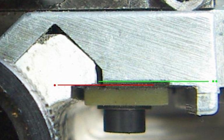
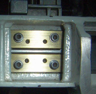
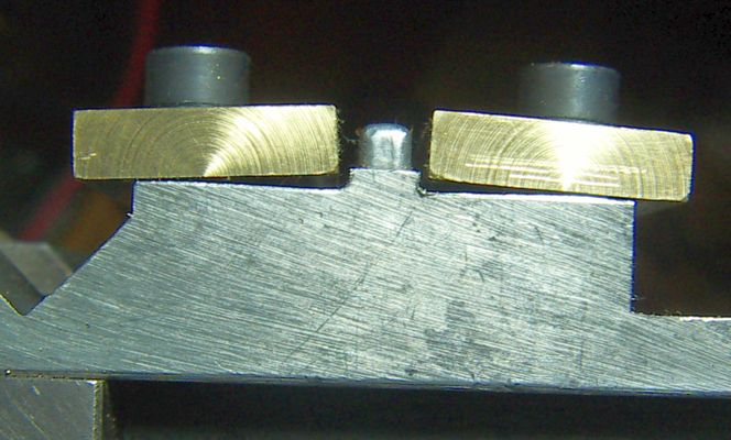
      Here is a photo showing what Kiwi Bloke wrote about:

      carrier_slide_fix.jpg

      The red line coincides with the surface underneath the front way where the lift strip has to tightened against and the green line coincides with the surface to which the lift strip is tightened.

      Due to a bad photograph, a shaky hand/mouse using mouse/MSPaint and a number of optical effects I cannot recall how to explain, the difference observed between the lines is really much less that what it appears to be.

      But it boils down to this:

      If both lines are at the same level, the lift strip will not touch the surface underneath the way and the carriage will move upwards, so the green line has to be above the red line.

      The same thing obviously applies to both lift strips.

      After a countless number of iterations ie: filing the surfaces, mounting the carriage, tightening the lift strips, checking the carriage movement and then unmounting it again to file off some more material, the stars finally started to line up.

      And the problem seems to have been fixed. Although promising, the jury is still deliberating.

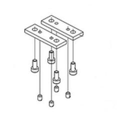
      As I will be replacing the ca. 1980 OEM lift strips with a new set made from 5/8"x5/32" brass, there will be photos to show what was done along with a description on how it was done to be kept here at ME for other U3 owners looking for a solution.

      I don't want to end this post without first tipping my hat to Kiwi Bloke for graciously posting both about the problem and a proven solution.

      Unless something else comes up, I hope to be posting further comments and a couple of photographs in a few days's time.

      Best,

      JHM

      Edited By Julius Henry Marx on 16/06/2023 22:44:51

      Advert
      #11496
      Julius Henry Marx
      Participant
        @juliushenrymarx92355
        #648778
        Michael Gilligan
        Participant
          @michaelgilligan61133

          Julius

          Whilst fully accepting the difficulty of photographing this arrangement … I find your image rather worrying: It appears that there is a gap on the right-hand [as viewed] slope of the prismatic bearing surface !

          Grateful if you could confirm that this is a mere illusion.

          … if it was real, you would have a lot of work to do !

          MichaelG.

          #648782
          Hopper
          Participant
            @hopper

            I wondered about that too. But assumed it was a trick of the light. If not, then yes, something definitely to be addressed.

            #648802
            Kiwi Bloke
            Participant
              @kiwibloke62605

              Well, thanks for the thanks Julius. It's always nice when there's evidence that one's posting has helped (or even been read and understood…).

              I wouldn't bother changing the strips. Just flatten them with a fine file. Beware abrasive paper, in case grit gets embedded. I would imagine that the material was chosen so that the strips could be tightened down in a loaded condition, without too much worry about seizing because of poor Not many people would boast about their expensive disappointment, would they?lubrication.

              It does seem ironic that it's not always easy to find complaints about machines' shortcomings, and grumbles about machine design, manufacture and performance before one buys a disappointment. (See also Ford Ecoboom thread!) Perhaps few people like to admit even to themselves that they've bought a lemon. However, once there's a trickle of discontent published, it's sometimes followed by a torrent…

              One could completely fill the forum with fully-justified gripes about Myfords, Emcos, Cowells, Fobcos and other 'well-respected' makes, but their owners seem to prefer to keep quiet – although freely making disparaging remarks about far eastern built-down-to-a-price-and-down-to-an-even-lower-quality machines. Not many people would boast about their expensive disappointment, would they? I'm impressed by the number of Cowells lathes that turn up for sale in apparently almost-unused condition. I wonder why. I could fill pages with my criticisms of the machine (if anyone's interested)…

              Sadly, there are plenty of areas of design and manufacturing weakness in Unimat 3 (and other Emco) machines: the U3 saddle 'lift strip' arrangement and the vertical quill's bearings have been discussed here, and Graham Meek and others have worked wonders on various improvements. With suitable attention, U3s can be made into useful, although very limited machines. But 'fresh out of the box', they are a gamble.

              #648817
              Julius Henry Marx
              Participant
                @juliushenrymarx92355

                Hello:

                Posted by Michael Gilligan on 17/06/2023 08:01:28:

                … appears that there is a gap …

                Posted by Hopper on 17/06/2023 09:20:35:

                … assumed it was a trick of the light.

                Quite so …

                There does appear to be a gap and just as worried as you, rushed to look at the carrier again to check.

                But no, it is indeed a trick of sorts.

                First, there was (not any more) a very slight burr casting a shadow, in turn made to look worse by having magnified the original image to try to get more detail of the problem at hand.

                And then there is what seems to be a very slight deformation of the aluminium casting, most probably produced while machining the underside of the carrier.

                So, fortunately there is no gap, at least not one that I can detect or measure at the moment.

                Thanks for mentioning it.

                Best,

                JHM

                Edited By Julius Henry Marx on 17/06/2023 13:13:44

                #648821
                Michael Gilligan
                Participant
                  @michaelgilligan61133

                  Thanks for checking … I am relieved, but probably not as much as you are !!

                  MichaelG.

                  #648826
                  Julius Henry Marx
                  Participant
                    @juliushenrymarx92355

                    Hello:

                    Posted by Kiwi Bloke on 17/06/2023 11:07:03:

                    … thanks for the thanks Julius.

                    You're welcome.

                    … nice when there's evidence that one's posting …

                    Your post has been very helpful and most importantly, it will be also helpful to others in the same pickle. Because that's what it is all about, no? ie: sharing and spreading knowledge.

                    … wouldn't bother changing the strips.

                    Ahh …

                    I've already made the new set, just need drilling and finishing but I will keep both your advise and the OEM strips. Worst case scenario, I'll can always go back to the plastic ones.

                    As the brass stock I purchased is 5/8" (15.9mm), I have kept the new strips at that width so as to avoid having to machine them down to 13mm and also a bit longer, 49mm instead of 47mm.

                    This new size comes in handy as the slightly larger surface will cover a good part of those cost-cutting voids between the strips and the carrier body (swarf does find its way in there!) and help with an experiment I want to run by placing small pads of SAE10 oil soaked felt in them, hopefully helping with the strips' lubrication and denying the swarf a place to reside in.

                    … not always easy to find complaints … | … before one buys a disappointment.

                    Yes, like you point out, no one likes or is willing to accept that they have purchased a lemon. Much less if said lemon was dry and very expensive.

                    … plenty of areas of design and manufacturing weakness in Unimat 3 … | … can be made into useful, although very limited machines.

                    Yes, but now it is my U3 so I have to / will make the best of it by (hopefully) manage to get it to work as intended/reported by everything I read about it.

                    Thanks for your input.

                    Best,

                    JHM

                    #648828
                    Julius Henry Marx
                    Participant
                      @juliushenrymarx92355

                      Hello:

                      Posted by Michael Gilligan on 17/06/2023 13:15:49:

                      Thanks for checking …

                      You're welcome.

                      … relieved, but probably not as much …

                      Yes, I am quite relieved that there is no gap I can (at least for now) detect / measure.

                      Once the new stips are in place and I can run a few tests to check how they are working ie: if they seize, etc. I will go about the procedure you posted in my previous thread and see how the carriage is behaving with respect to the ways.

                      We'll see then if any painting, scraping / diamond disking is needed.

                      The new screw nut I made for the cross slide seems to be working well enough but the backlash inherent to the M8*1 LH thread is still there as I have not yet practised the slit or drilled for the small screws to be able to make the necessary adjustments.

                      Thanks a lot for your input.

                      Best,

                      JHM

                      Edited By Julius Henry Marx on 17/06/2023 14:09:01

                      #648838
                      Michael Gilligan
                      Participant
                        @michaelgilligan61133

                        Posted by Julius Henry Marx on 17/06/2023 12:59:11:

                        […]

                        And then there is what seems to be a very slight deformation of the aluminium casting, most probably produced while machining the underside of the carrier.

                        […]

                        .

                        dont know

                        Now there’s a thing for the wise folks on this forum to ponder [preferably on your other thread]

                        Why do they consider a good Aluminium alloy unsuitable for the strips, when the ‘carrier’ is an ‘aluminium casting’ ?

                        MichaelG.

                        #648848
                        Julius Henry Marx
                        Participant
                          @juliushenrymarx92355

                          Hello:

                          Posted by Michael Gilligan on 17/06/2023 15:12:18:.

                          … a thing for the wise folks on this forum to ponder …

                          I'm just the beginner who had doubts about the use of aluminium alloy for the lift strips in the first place as the purveyor's recommendation (from the start) did not match what I had seen (steel, cast iron, brass, bronze, Delrin type plastics and Teflon) which is why I asked.

                          Reading the replies, the lack of precedent in the use of aluminium alloy gibs (and other uses such as bearings) plus the possibility of aluminium oxide working against the cast steel ways made the decision clear for me.

                          But as you well point out, the carrier is made from aluminium alloy.

                          So I think yours is a valid question that would, should there be enough members interested, merit a another, different thread. eg: suitable materials for making gibs, lift strips and similar parts.

                          Personally, I don't think that the carrier being made from an aluminium alloy can justify the use of that same material for the lift strips.

                          Like I have pointed out, I'm just the beginner with the question.

                          But should you ask me, my answer would be that the use of an aluminium alloy to manufacture the carriage was, along with its defective design, the worst manufacturing decision Emco could have made with the Unimat 3.

                          Thanks a lot for your input.

                          JHM

                          Edited By Julius Henry Marx on 17/06/2023 17:33:17

                          #648882
                          Dave S
                          Participant
                            @daves59043

                            Pretty sure the saddle is not "aluminium". I think it's mazac or similar alloy.

                            The headstock and tailstock castings are also the same mazac type alloy.

                            Dave

                            Edited By Dave S on 17/06/2023 21:37:17

                            #648883
                            Michael Gilligan
                            Participant
                              @michaelgilligan61133

                              Plenty of choices there, Dave : **LINK**

                              https://en.wikipedia.org/wiki/Zamak

                              Whilst we’re guessing … do you know if any of them have particular merit as a bearing ?

                              MichaelG.

                              .

                              Edit: __ I can find no hints here: https://xometry.eu/en/die-casting-materials-selection-guide/

                              Edit: __ but I have found some excellent photos of a used casting, here:

                               https://www.thetoolsquirrel.co.uk/ourshop/prod_7617822-Emco-Lathe-Spares-Emco-Unimat-3-Bed-Slide.html

                              with visible wear marks on the prismatic bearing-surfaces.

                              Edited By Michael Gilligan on 17/06/2023 22:02:53

                              #648896
                              Julius Henry Marx
                              Participant
                                @juliushenrymarx92355

                                Hello:

                                Almost there …

                                Posted by Julius Henry Marx on 17/06/2023 13:54:37:

                                … already made the new set, just need drilling and finishing …

                                Decided to start with the finishing, made more sense and expect it will make marking/drilling with precision a bit easier.

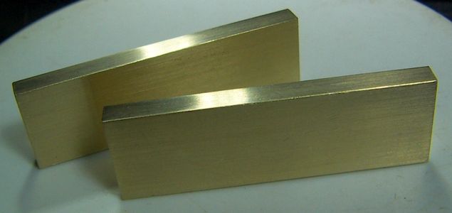
                                lift_strips_1.jpg

                                The surfaces shown in the photograph are the only ones with a finish. With my milling table not being operational yet, the narrow side and the ends of the strips were squared off on the U3 and the wide side finished by hand with sandpaper on a glass plate.

                                Since I do not intend to make them double sided or interchangeable, the other two surfaces will stay as they came from the purveyor.

                                Best,

                                JHM

                                #648908
                                Dave S
                                Participant
                                  @daves59043

                                  The original bar bed Unimat made extensive use of zamak, so as a material for small lathe use Emco already had experience (and presumably a supply chain).

                                  Atlas (I think) lathes in the USA used zamak changewheels, and various other machine parts in various other machines are made of it.

                                  It’s relatively cheap, casts well and is roughly as strong as brass, whilst being slightly softer than iron/steel.

                                  I believe it also has good vibration damping properties.

                                  Dave

                                  #648913
                                  Michael Gilligan
                                  Participant
                                    @michaelgilligan61133

                                    No problem with any of that, Dave … but it doesn't really address its suitability as a sliding bearing material: Which [unless anyone knows otherwise], I would venture to suggest is no better than the hard aluminium alloy which was derided by most posters on the other thread.

                                    MichaelG.

                                    #648932
                                    Dave Halford
                                    Participant
                                      @davehalford22513

                                      I don't think the Unimat3 was ever intended to be used a a serious lathe – the 10 fulfils that roll.

                                      #648933
                                      Hopper
                                      Participant
                                        @hopper

                                        Myford lathes use a lot of Mazak (same as Zamak) on peripheral parts such as the motorising unit frame and H frame, belt guards, gear guards, leadscrew brackets, cross slide end bracket and the awful little ML7 cross and top slide dials. But not any of the main moving parts, thank goodness.

                                        I think its main component is zinc, with lesser amounts of aluminum and copper. Never seen it used as a bearing. Always seems to be a brass or bronze sleeve in it, eg Myford leadscrew mounting brackets.

                                        #648946
                                        Julius Henry Marx
                                        Participant
                                          @juliushenrymarx92355

                                          Hello:

                                          Posted by Dave S on 18/06/2023 07:51:46:

                                          … Unimat made extensive use of zamak … | … roughly as strong as brass …

                                          Posted by Michael Gilligan on 18/06/2023 08:50:41:

                                          … doesn't really address its suitability as a sliding bearing material … | … suggest is no better than the hard aluminium alloy which was derided by most posters …

                                          Posted by Hopper on 18/06/2023 11:23:01:

                                          Myford lathes use a lot of Mazak … | Never seen it used as a bearing. Always seems to be a brass or bronze sleeve in it …

                                          @Dave, @Michael, @Hopper:

                                          As an architect by trade and amateur photographer for quite a few years, one of my favourite phrases/quotes has always been "a picture is worth a thousand words", said to be attributed to an advertising executive in the first decades of the 20th. century.

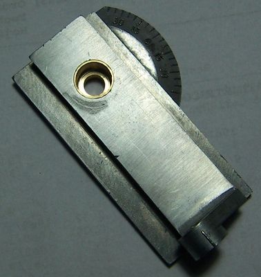
                                          To wit: the photos I am posting below belong to the "taper turning" or "top slide" accessory (part #150 190) that came with my Unimat 3, a part that a firm by the name of Blue Ridge Machinery and Tools at some point had on their Unimat 3 parts catalogue for a cool US$49.00 and these days can command silly money prices. (~ £80/100).

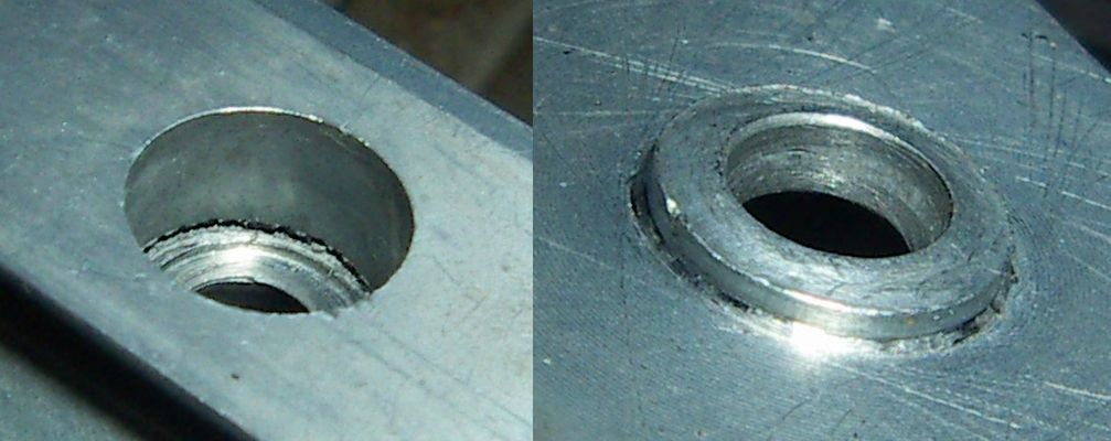
                                          The attachment's base was probably manufactured with the same material as the cross slide and the result of that can be clearly seen in the photograph below:

                                          slide_damage.jpg

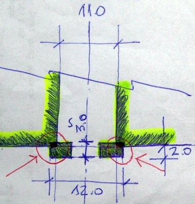
                                          If that were not enough, while taking measurements prior to attempting to repair the damage, I discovered that the cylindrical protusion than moves/pivots inside the recess in the cross slide has very little material in common with the base itself and was most probably a tad short.

                                          Here is the sketch I made at the time:

                                          detail.jpg

                                          As you can see, there is very little material at work to take the stress, something closely resembling a 11.0 x 12.0  x 1.0 mm washer made from Zamak.

                                          How do you say "salt to the wound" in German? 8^°

                                          Fortunately, I eventually managed to figure out a way to repair it with a piece of brass rod, the end result being this:

                                          ready.jpg

                                          I have not had a chance to use it as yet, but I expect that once I make a new set of gibs for it, it will work as intended.

                                          I expect these photographs serve as a definite/suitable example of Mazak/Zamak used to manufacture the wrong part, in the wrong place for the wrong reasons.

                                          My thanks you all of you for your input.

                                          Best,

                                          JHM

                                          Edited By Julius Henry Marx on 18/06/2023 14:11:21

                                          #648985
                                          Michael Gilligan
                                          Participant
                                            @michaelgilligan61133

                                            Please forgive the digression, but I think this current ebay auction is evidence [if any were needed] that Emco Unimat has a certain mystique: **LINK**

                                            https://www.ebay.co.uk/itm/385684950238

                                            MichaelG.

                                            #648989
                                            Julius Henry Marx
                                            Participant
                                              @juliushenrymarx92355

                                              Hello:

                                              Posted by Michael Gilligan on 18/06/2023 17:53:39:

                                              … forgive the digression …

                                              No problem, today is still Sunday so all is forgiven. But tomorrow is another day, so standard rules apply. 8^)

                                              … Unimat has a certain mystique …

                                              Indeed …

                                              Both certain and unjustified, save only because of the hype and the scarcity, combination which turned it into a collector's item.

                                              In the same catalogue I mentioned previously, a ten piece 1.0 to 8.0 mm ES-16 type collet set (part #152 200) was offered for US$375.00 with additional collets (0.5-1.00 mm to 7.0-8.0 mm) went for US$38.50 each.

                                              A small fortune. I don't have a date for the catalogue but I'd wager that it is post Emco discontinuing the Unimat 3.

                                              That said, Emco still has some Unimat 3 parts for sale. Their webpage (German language only) has the newer ESX16 version of the chuck (M14x1 thread) for €63.60.

                                              The original OEM E-16 collets were standard Schaublin fare ie: very good but quite expensive, as all good quality precision tools are.

                                              Emco sill has a 15 piece (?) set of ESX25 collets in 0.5-1.00 mm (?) to 15-16 mm (?) sizes for €180.00 but I don't who the OEM is.

                                              Thanks for your input.

                                              Best,

                                              JHM

                                              Edited By Julius Henry Marx on 18/06/2023 19:29:12

                                              #649115
                                              Julius Henry Marx
                                              Participant
                                                @juliushenrymarx92355

                                                Hello:

                                                Significant progess has been made albeit not without some annoyances, the net result being what seems to be a suitable outcome, at least for now. Time will tell.

                                                I will most probably have to make some adjustments on the surfaces where the lift strips are mounted once they settle in with use for (as expected) the ways in this ca. 1980 U3 have some wear and the carriage gets stiffer as it moves near the headstock and tailsock but not too much.

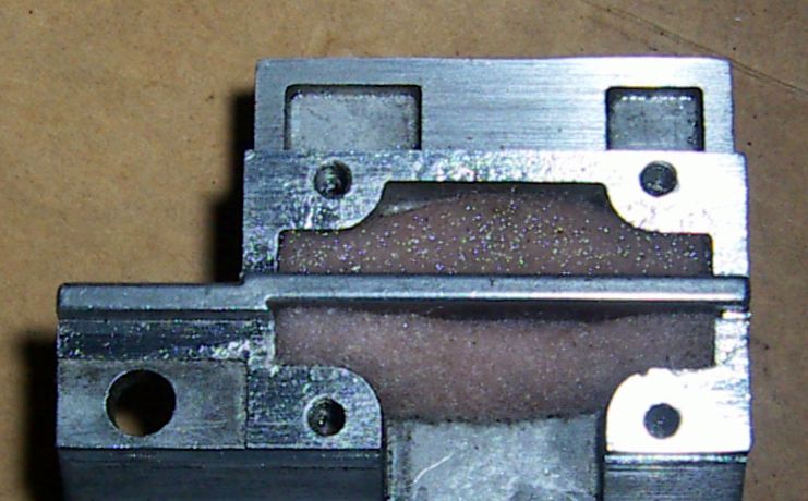
                                                As mentioned previously, an oil soaked felt pad was placed under each strip:

                                                oil_pad.jpg

                                                It is an experiment to see if, apart from keeping swarf out, will also aid in keeping the carriage running smoothly. An old but proven idea, looks like it will work as expected.

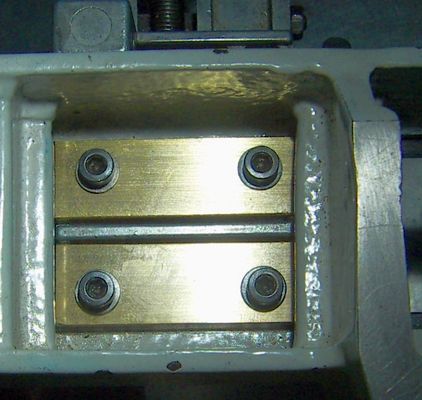
                                                Here is what the final product looks like:

                                                in_place.jpg

                                                The length of the strips cover the whole length of the mounting surface which is 49 mm and their width is roughly the same as that of the brass stock my purveyor had on special offer at the time, 5/8".

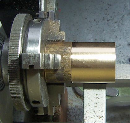
                                                Once I had everything in place, I took to cleaning up a short piece of 25mm SAE64 bronze which I will use to make a bushing, with this result:

                                                first_job.jpg

                                                Granted, it is only 25mm worth of clean-up but I was very happy to see that my micrometer informed me that it is perfectly cylindrical, something I was absolutely unable to achieve a week ago.

                                                It surprised me to see how much material had to be removed to get the strips to touch the ways as needed. I intended to measure it but was too concentrated in what I was doing and totally forgot.

                                                If I had to guess, I'd think something like 0.02/0.03mm, at least.

                                                As a side note, I would mention that while I was looking for a solution to the problem I was having with the U3 carriage, I recalled that that the Sieg C0/Grizzly G0745 were close clones/copies of the Unimat 3 and decided to look to what was available in terms of spare parts and if their lift strips would work on the U3.

                                                The (steel?) replacement gibs these Sieg manufactured lathes use are held in place in the same manner as the Unimat (a pair of 6mm M4x0.7 screws) but each gib has an additional pair of threaded holes to hold set screws used to regulate the distance of the lift strips to the ways and keep them from being overtightened.

                                                An interesting solution to this problem but probably not applicable to the Unimat 3 carriage: I think (?) the carriage used in the Sieg C0 is 1. made from steel and 2. does not have any voids so the set screws have a spot to lift land on.

                                                siegc0_strips.jpg

                                                That is all for the time being.

                                                Thanks to all for your input.

                                                Best,

                                                JHM

                                                Edited By Julius Henry Marx on 20/06/2023 14:56:58

                                                #649160
                                                Julius Henry Marx
                                                Participant
                                                  @juliushenrymarx92355

                                                  Hello:

                                                  @Kiwi Bloke: thank you very much for taking the time to write up your very comprehensive explanation.

                                                  If you don't object/mind, I'll post the answer here as (I think) it makes more sense given this thread's context.

                                                  Posted by Kiwi Bloke on 20/06/2023 21:36:43:

                                                  … scaling things can cause problems. | … as linear dimensions increase, mass increases with a cube law.

                                                  Indeed … I knew it was not linear but did not know that it was that much ie: cubed.

                                                  … the anti-lift strips are vital … | … gravity isn't doing enough to locate the saddle. They are non-adjustable (unlike the Sieg – interesting…), and it appears that saddle manufacture has, in their location surface's regard, wide tolerances.

                                                  Yes, the Sieg set screws jogged my memory and got me thinking.

                                                  … my belief that the choice of a plastic material by Emco is intelligent, not negligent.

                                                  I will take your word for that, you are far more experienced/knowledgeable than I. But I think you can agree with me that, at best, it looks like one intelligent choice vs. a great many negligent ones. The list is quite long.

                                                  … Sieg's adjustable strip approach is necessary for metal strips. Metal may be OK, if carefully fitted, but wear will destroy the fit.

                                                  Yes, I had been thinking all day about the wear the brass strips would be subject to. Even with good lubrication the strips would wear but then, (I think) not to the point of generating a gap between the ways and the strip. ie: the strips will suffer wear till they are not touching enough to cause more wear. Of course, at that point there's also swarf between ways and strips to take into account and that is when things will start to get complicated.

                                                  This afternoon I vaguely recalled a web page by some US chap with a Chinese 7×14 lathe (or similar) where he explained a modification he devised to allow him to adjust the carriage strips from above and on the fly. ie: no dismantling anything.

                                                  Cannot find the page now but the idea was similar in concept to what the people at Sieg did with the C0 strips so I set to see if I could do something like that with the U3 strips.

                                                  Here it is:

                                                  after_tilting.jpg

                                                  Each strip has acquired two 12mm M4x0.70 set screws, but unlike the Sieg C0 strips, the screws are not aligned with the screws holding the strips in place but offset so as to do this when adjusted:

                                                  the_tilt.jpg

                                                  The screws holding the strips are not tightened and the set screws cause the strips rock towards the ways.

                                                  It goes without saying that the amount of tilt shown in the photograph has been greatly exaggerated in order to show what happens when the strips are being adjusted. The strips do not load on the ways, they hover just above them on a film of oil so I expect that they will last a long time.

                                                  I finished the job a while ago and can say that it works really well: the slide (tested without lead screw fitted) goes from end to end very smoothly, with no jamming whatsoever and no discernible upwards movement at any point in its travel.

                                                  Of course, it has to be tested and used for a good while to see the actual results but (for now) it is looking good.

                                                  Once again, thank you so much for the explanation on how the strips work. Learned something today.

                                                  Best,

                                                  JHM

                                                  #649167
                                                  Kiwi Bloke
                                                  Participant
                                                    @kiwibloke62605

                                                    …carrying on from my post on your other thread (confused? So am I…).

                                                    The important thing here is, I believe, preload. It's difficult to arrange and control preload when a system is too rigid. Hence my belief that, counter-intuitive though it may be, Emco got it right. Or, at least more so than Sieg.

                                                    The Sieg approach looks attractive at first sight, but I suspect that it's another example of their blindly copying design ideas rather than thinking things through thoroughly. Compared to Emco's design and manufacturing integrity, I consider the Sieg machines to be seriously inferior in many areas. (I'm probably going to cop a lot of flack for that remark, and don't wish to start a war, so let's just leave it as a statement of a personal opinion…).

                                                    #649171
                                                    Kiwi Bloke
                                                    Participant
                                                      @kiwibloke62605

                                                      …and replying to your post above.

                                                      Interesting approach. No doubt your approach will work fine. Whether it will continue to do so as it wears remains to be seen. Realistically, it isn't going to wear much is it?

                                                      However, a few things to consider:

                                                      1. Tilting the strips will tend to cause line contact, which will be associated with greater wear. Don't forget that a softer material can wear a harder one if it gets embedded with abrasive – as in a lap. These strips need to be 'sacrificial'.

                                                      2. You could use Belville washers (or other spring washers) under the retaining screw heads to achieve preload. (IIRC, Emco use wavy spring washers).

                                                      3. The strips will certainly not float on a film of oil (hydrodynamic bearing), unless you make the gap large enough (and the saddle whizzes along) – and we don't want a gap, for obvious reasons. At the low speed a saddle will travel, and the loading necessary to pull the saddle down, even boundary lubrication is optimistic. There will be metal-to-metal contact.

                                                      4. Don't lose sleep over it. "She'll be right", as they say here in NZ.

                                                    Viewing 25 posts - 1 through 25 (of 37 total)
                                                    • Please log in to reply to this topic. Registering is free and easy using the links on the menu at the top of this page.

                                                    Advert

                                                    Latest Replies

                                                    Home Forums Beginners questions Topics

                                                    Viewing 25 topics - 1 through 25 (of 25 total)
                                                    Viewing 25 topics - 1 through 25 (of 25 total)

                                                    View full reply list.

                                                    Advert

                                                    Newsletter Sign-up