Unimat 3 carriage feed screw – material used.

Advert

Unimat 3 carriage feed screw – material used.

Home Forums Beginners questions Unimat 3 carriage feed screw – material used.

Viewing 25 posts - 1 through 25 (of 48 total)
  • Author
    Posts
  • #11503
    Julius Henry Marx
    Participant
      @juliushenrymarx92355
      Advert
      #650070
      Julius Henry Marx
      Participant
        @juliushenrymarx92355

        Hello:

        The OEM carriage feed screw on my Unimat 3 one came with damaged threads at the end of the M5 section, where the handwheel is fixed.

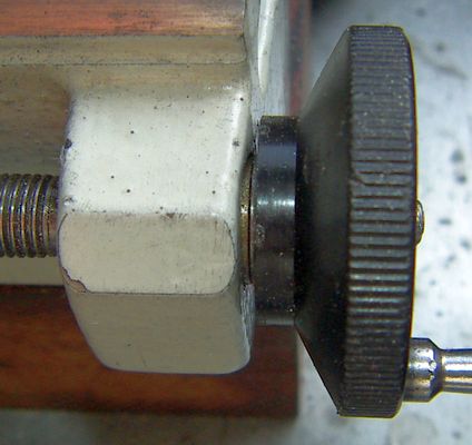
        I managed to solve that problem (temporarily) by doing away with enough of the cylindrical part of the handwheel so that the nut that fixes in place would thread in properly, losing the ability to have an idea of how much I was advancing the carriage.

        The other very annoying problem it came with was that the edge of the plastic with the numbers/divisions rubbed against the end of the bed.

        This because, instead of a uniform flat surface at right angles to the bed, it has a roughly finished curved one. 8^°

        Putting a light bevel on the plastic and adding a polished brass washer made a world of difference.

        handwheel.jpg

        So, aside from a new handwheel, I am going to need a new carriage feed screw.

        The options I have seen are:

        1. a used one on the web. (not really)
        2. a new one made by Sieg for the discontinued Sieg C0
        3. a new one made locally (if I can find someone to do it)

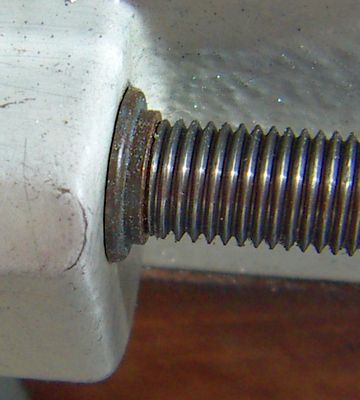
        The last option would solve a third problem I ran into when I first disassembled the machine: the length of the threaded section of the OEM carriage lead screw is actually shorter than needed by a few millimeters, requiring a 6mm x 8mm brass washer of the right thickness at the left end to fix it.

        pwr_drive.jpg

        I have checked the length of the thread in the available Sieg part and they are the same as the one I have. ie: 302mm

        I don't have the specification for the steel used in the OEM part so as to see about having one made or if maybe some other more suitable steel could/should be used.

        I'd appreciate comments on this.

        Thanks in advance.

        JHM

        #650073
        John Haine
        Participant
          @johnhaine32865

          IIRC the thread is M8 x 1 LH. I doubt that the original steel was particularly distinguished by great hardness – a good free cutting mild steel would do especially as it runs in a thread cut in MAZAK. The handwheels IMHO are deplorable – why not make a new one out of nice aluminium alloy to dimensions that will fit the end of the leadscrew? And you might consider taking the thread down to M4 so it's threaded nicely all along.

          #650080
          Julius Henry Marx
          Participant
            @juliushenrymarx92355

            Hello:

            Posted by John Haine on 26/06/2023 17:10:51:

            IIRC the thread is M8 x 1 LH.

            Yes, that I was aware of.

            … doubt that the original steel was particularly distinguished … | … mild steel would do especially as it runs in a thread cut in MAZAK.

            Makes sense. ie: your deduction, certainly not the use of Mazak for a non-replaceable carriage lead screw.

            … handwheels IMHO are deplorable …

            Quite so, just like the rest of the power train arrangement.

            Incredible that the right end of the lead screw gets reduced to ⌀ 5mm before going into the steel bushing to then be threaded to M5x0.8 for the handwheel. Someone was not thinking right …

            … new one out of nice aluminium alloy …

            I purchased some Chinese made ones some time ago but will have to make some other modifications to be able to use them as they are.

            … taking the thread down to M4 …

            I think that the leadscrew should be properly supported at the right end, ie: in the same way it is at the left end, ⌀ 6.0 mm inside a steel/bronze bushing.

            To that effect, whatever system is used to secure the handwheel should be implemented from the steel bushing/bronze onwards, ie: towards the right. This would mean a new, different bushing design and handwheel arrangement.

            Thank you for your input.

            Best,

            JHM

            #650107
            Kiwi Bloke
            Participant
              @kiwibloke62605

              Julius – I may be at cross-purposes, and my U3 is not to hand, at present, so what follows may be less than helpful…

              The leadscrew should indeed be well supported at its right-hand end, but it is minimally loaded an any radial direction, so a 'feeble'-looking bearing, of small diameter, is OK. What is critical, however, is that the leadscrew must be properly axially constrained, thus thrust bearings are required to react screw thrust in both directions. The thrust bearing arrangement needs to be adjustable. Emco's threaded handwheel and nut design isn't the best – in fact their feedscrew axial constraint and thrust bearings are poor on many of their smaller machines – but, with patience and bad language, it can be just about be made to work – just not very nicely. You've already discovered that it may be necessary to fettle the face of the handwheel.

              What happens at the leadscrew's left-hand end doesn't really matter, as far as axial constraint is concerned, so an apparent gap is OK.

              If this isn't clear, the point is that axial constraint of the leadscrew should be afforded by its right-hand bearing (only). Plenty of opportunity to improve things here…

              You could probably salvage the right-hand end's end (?) by axially drilling the leadscrew and fitting an extension into the hole (threaded + Loctite), and then turning it back to desired dimensions to fit bush, handwheel, etc..

              Edited By Kiwi Bloke on 27/06/2023 02:06:03

              #650114
              JasonB
              Moderator
                @jasonb

                Would have been easier to counterbore the handwheel so the nut could be screwed on further and then no need to machine off the markings. Could still be done with a replacement handwheel.

                Rather than shaping the end of the handwheel and using a brass washer all that is needed to get clearance is to  slide the bush out a bit so the handwheel doe snot contact the casting. Loosened mine off to show how it can be slid out (not that much) so handwheel does not contact casting As Kiwi says let the left hand end float axially

                20230627_073529[1].jpg

                Never felt the need to modify mine, if I can make a Stuart 10V on it that will run just by blowing into it then what comes of the machine is OK by me.


                Edited By JasonB on 27/06/2023 07:40:47

                #650126
                Martin Connelly
                Participant
                  @martinconnelly55370

                  Agree with Kiwi Bloke, drill into the end of the leadscrew, tap it and Loctite in a stud of the correct length and thread. My bet would be that if there is any hardening it is only on the surface, not through to the core.

                  Martin C

                  Edited By Martin Connelly on 27/06/2023 10:09:10

                  #650127
                  JasonB
                  Moderator
                    @jasonb

                    If you do drill it out and fit a new part then you would need to make sure it is concentric as the 5mm dia is what runs in the bearing

                    #650133
                    Graham Meek
                    Participant
                      @grahammeek88282

                      Moving the Leadscrew Bush to the right a little would have removed any fouling problems as regards the handwheel rubbing the Bed. Rather than reduce the Handwheel a simple grubscrew inserted into the handwheel and impinging on the end of the M5 leadscrew thread would have locked the two together.

                      Emco used to use this method of locking on the Emcomat 7, Compact 8, with an additional lock nut.

                      Regards

                      Gray,

                      #650180
                      Julius Henry Marx
                      Participant
                        @juliushenrymarx92355

                        Hello:

                        Posted by Kiwi Bloke on 27/06/2023 02:00:03:

                        … what follows may be less than helpful…

                        All your posts have been quite helpful.

                        … leadscrew should indeed be well supported at its right-hand end, but it is minimally loaded …

                        Yes, I agree it is/may be minimally loaded. But then, why did the OEM turn it down to ⌀ 5mm? Emco would have left it at the same diameter as the left hand end and used a screw to fit the handwheel in place.

                        … critical, however, is that the leadscrew must be properly axially constrained …

                        Quite so. But as both the threaded section of the leadscrew and the right steel bearing are shorter than they should be, there is no proper axial constraint. Hence the washer at the left hand of the leadscrew and the need to add small washers at the right end to keep the handwheel from seizing.

                        …leadscrew's left-hand end doesn't really matter, as far as axial constraint is concerned …

                        Given my situation (ie: right hand M5 damage) the washer solved the axial movement I had which, combined with the backlash, was very annoying.

                        … the point is that axial constraint of the leadscrew should be afforded by its right-hand bearing (only).

                        Indeed …

                        Provided it is the right length so as to be able to make any necessary adjustments and at the same time provide a surface for the inner face of the handwheel to land on. That was not possible for me without the left hand washer, mainly because of the M5 damage.

                        … probably salvage the right-hand end's end (?) by axially drilling the leadscrew and fitting an extension …

                        Yes, I have been thinking about that quite a bit lately. But I'd need another working lathe or a spare leadscrew to do the job on my U3.

                        That's what I may end up doing, it will alow me to make all the modifications I need.

                        Thank you very much for your input.

                        Best,

                        JHM

                        #650183
                        Julius Henry Marx
                        Participant
                          @juliushenrymarx92355

                          Hello:

                          Posted by JasonB on 27/06/2023 10:20:59:

                          … then you would need to make sure it is concentric …

                          Of course. But if/when doing that the part I will fit will be the same diameter as the left end ie: 600) and work in tandem with a new, longer bushing with a flange where the inner surface of a new, different handwheel will land on.

                          Than you for your input.

                          Best,

                          JHM

                          #650184
                          JasonB
                          Moderator
                            @jasonb

                            Backlash/movement of the leadscrew is adjusted by how far the handwheel is screwed onto the 5mm thread and then locked in position with the domed nut, this sets a slight gap between the 8mm dia of teh screw and the face of the bearing. There is no need for all those washers, properly adjusted the handwheel won't seize or rub against the casting.

                            #650185
                            Julius Henry Marx
                            Participant
                              @juliushenrymarx92355

                              Hello:

                              Posted by Graham Meek on 27/06/2023 11:12:30:

                              Moving the Leadscrew Bush to the right a little … | … grubscrew inserted into the handwheel …

                              Yes. But the handwheel was already in very bad shape so I really did not mind shaving a part off. I was woeking on a bushing and got the best of me.

                              For the time being (till the leadscrew gets fixed and a new handwheel gets made) it works surprisingly well.

                              Thanks for your input.

                              Best,

                              JHM

                              #650193
                              Julius Henry Marx
                              Participant
                                @juliushenrymarx92355

                                Hello:

                                Posted by JasonB on 27/06/2023 18:11:51:

                                Backlash/movement of the leadscrew is adjusted by how far the handwheel is screwed …

                                … properly adjusted the handwheel won't seize or rub against the casting.

                                Yes. But the 5mm threads in my U3's leadscrew were damaged when I purchased it. There was no way I could adjust that properly.

                                Posted by Julius Henry Marx on 26/06/2023 16:16:50:
                                … OEM carriage feed screw on my Unimat 3 one came with damaged threads at the end of the M5 section, where the handwheel is fixed.

                                Thanks for your input.

                                Best,

                                JHM

                                #650217
                                Bazyle
                                Participant
                                  @bazyle

                                  Looks like losing the handwheel graduations is a bonus. Turn or even 3D print a new scale holder of much larger diameter to friction fit over the remaining parallel section.

                                  #650244
                                  Kiwi Bloke
                                  Participant
                                    @kiwibloke62605

                                    Julius – Just read your reply. Understood. The wretched thing is making life difficult for you…

                                    Just a thought – if you could improvise a temporary saddle stop, you could still turn the end of the leadscrew. Just slowly feed the saddle along the bed by carefully and sensitively pushing it by hand. The leadscrew will fit in the spindle bore.

                                    #650245
                                    Graham Meek
                                    Participant
                                      @grahammeek88282
                                      Posted by Julius Henry Marx on 27/06/2023 18:16:35:

                                      Hello:

                                      Posted by Graham Meek on 27/06/2023 11:12:30:

                                      Moving the Leadscrew Bush to the right a little … | … grubscrew inserted into the handwheel …

                                      Yes. But the handwheel was already in very bad shape so I really did not mind shaving a part off. I was woeking on a bushing and got the best of me.

                                      For the time being (till the leadscrew gets fixed and a new handwheel gets made) it works surprisingly well.

                                      Thanks for your input.

                                      Best,

                                      JHM

                                      Lightly skimming the end of the handwheel to get a flat surface would not have removed the entire graduations.

                                      Removing the damaged M5 thread portion would have meant the end of the Leadscrew was now inside the handwheel.

                                      Inserting an M5 Grub or Set screw into the M5 hole would have locked the the handwheel to the leadscrew, after most of the play had been removed from the assembly.

                                      If the Grub or Set screw was sufficiently long enough an M5 nut on the outside would have further locked this setting permanently.

                                      As stated previously this is a standard Emco adjustment.

                                      Using this method and a replacement handwheel would not require a new leadscrew.

                                      Incidentally both these items are regularly up for sale from various vendors. Plus original parts can still be had from Holz & Hobby. The newer handwheels with white graduations have a steel insert.

                                      Regards

                                      Gray,


                                      Edited By Graham Meek on 28/06/2023 11:20:08

                                      #650246
                                      Kiwi Bloke
                                      Participant
                                        @kiwibloke62605

                                        Julius – Just read your reply. Understood. The wretched thing is making life difficult for you…

                                        Just a thought – if you could improvise a temporary saddle stop, you could still turn the end of the leadscrew. Just slowly feed the saddle along the bed by carefully and sensitively pushing it by hand. The leadscrew will fit in the spindle bore.

                                        Regarding your idea of having a larger diameter thrust face 'where the inner surface of a new, different handwheel will land on', just be careful. The face of the handwheel must run without wobble, but this is difficult to achieve if it's located by a non-precision, sloppy thread. The larger diameter, the more this is a problem. You may end up with a handwheel whose resistance to turning varies with rotation. That always feels horrible.

                                        I would direct more attention to the right-hand end of the leadscrew and its bearing on the bush. I think Emco tended to make feedscrew thrust bearings too small in diameter. An interposed hard steel shim washer can work wonders. This is the thrust bearing that takes the cutting forces – the leadscrew is trying to escape to the right.

                                        #650247
                                        JasonB
                                        Moderator
                                          @jasonb

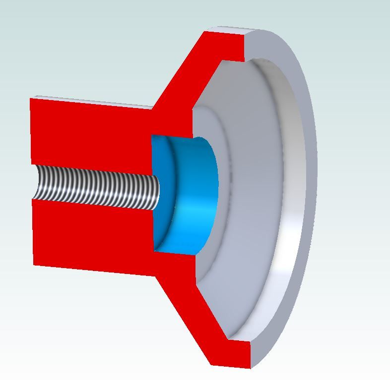
                                          In the same way as Graham's suggestion of a grub screw would have saved removing the scale. My suggestion of forming a counterbore (shown in blue) would have allowed a nut to be used on an undamaged length of thread assuming it was the thread within the original nit that got stripped.

                                          u3 handle.jpg

                                          #650253
                                          Julius Henry Marx
                                          Participant
                                            @juliushenrymarx92355

                                            Hello:

                                            Posted by Kiwi Bloke on 28/06/2023 11:11:48:

                                            … making life difficult for you…

                                            Well … If it were only the U3 … 8^)

                                            For the time being I am doing (surprisingly) well with the washers, handwheel surgery, etc. so that is not a huge problem at the moment, but I don't want this hack to be a perma-temporary thing.

                                            So I have sent for a replacement feed screw from a vendor of all things Sieg at Aliexpress. If the photos are anything to go by, it looks like it is much better made than the one from my U3:

                                            ls_ends.jpg

                                            The main reasons for having sent for a new one (aside from the original one being 43 years old and in awful shape) being the ready-made availability and the real life difficulty of getting a shop to make a bespoke one for me, much more being just one and not two dozen.

                                            My plan is to make a part with the same diameter as the left end of the leadscrew (6mm) and a full length concentric hole with a M5x0.8 thread, obviously with a non-threaded part for it to fit properly.

                                            This part will most probably be made out of hard bronze and be threaded into/ locked with a suitable (soft) anaerobic to the right end of the screw. The length this part will be defined when I decide how to fix a new handwheel and/or some attachment. eg: a toothed pulley to drive the feedscrew FF / FR using a small 12V motor.

                                            The right end of the feedscrew, now having a longer ⌀ 6mm end with a male M5x0.8 hole will run inside a new, longer steel bushing with a flange on its right side, maybe with a small recess to hold a small thrust bearing if I can find a suitable one.

                                            …. improvise a temporary saddle stop … | … turn the end of the leadscrew.

                                            I thought for some time of doing that same thing before fixing (?) the lift strip problem, but concluded that it was not something to do without risking making things worse.

                                            Thank you very much for your input.

                                            Best,

                                            JHM

                                            #650254
                                            Kiwi Bloke
                                            Participant
                                              @kiwibloke62605

                                              May have misunderstood, but the 'proper' thrust bearing should be on the left side of the supporting bush.

                                              Interesting that there's may be other possibilities for getting some new bits that can be modified for Emco machines.

                                              #650256
                                              JasonB
                                              Moderator
                                                @jasonb

                                                As everything has to be inserted through from the right hand hole it will be difficult to put a thrust bearing on the left side of that hole.

                                                #650259
                                                Julius Henry Marx
                                                Participant
                                                  @juliushenrymarx92355

                                                  Hello:

                                                  Posted by Kiwi Bloke on 28/06/2023 11:22:49:

                                                  … idea of having a larger diameter thrust face … | … be careful. The face of the handwheel must run without wobble …

                                                  Indeed … | Been there, seen that, suffered handwheels in other tools/equipment.

                                                  … direct more attention to the right-hand end of the leadscrew …

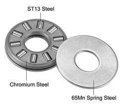
                                                  Yes, which is why the flange I am planning to add to the new bushing will have to have a thrust bearing before the new handwheel which would also provide the smooth running hard steel shim washer you mention.

                                                  thrust_bearing.jpg

                                                  The thing will be to source the right size bearing with a 6mm bore.

                                                  Thank you for your input.

                                                  Best,

                                                  JHM

                                                  Edited By Julius Henry Marx on 28/06/2023 13:12:29

                                                  #650265
                                                  Julius Henry Marx
                                                  Participant
                                                    @juliushenrymarx92355

                                                    Hello:

                                                    Posted by JasonB on 28/06/2023 12:28:14:

                                                    … everything has to be inserted through from the right hand hole …

                                                    Of course … 8^)

                                                    Right threads end | -> bushing with flange | -> flat thrust bearing | -> handwheel  <<- leadscrew inserted from here

                                                    ^^^ This whole arrangement, if properly assembled, can be removed/replaced buy just loosening the set screw at the right hand side and unscrewing the last few cm.

                                                    Than you for your input.

                                                    Best,

                                                    JHM

                                                    Edited By Julius Henry Marx on 28/06/2023 13:11:52

                                                    #650266
                                                    JasonB
                                                    Moderator
                                                      @jasonb

                                                      But as Kiwi says the thrust is coming from the other direction so you really want the cutting forces to push against the thrust bearing so it needs to be on the left of the bearing. Otherwise all it is doing is giving a bit of preload.

                                                    Viewing 25 posts - 1 through 25 (of 48 total)
                                                    • Please log in to reply to this topic. Registering is free and easy using the links on the menu at the top of this page.

                                                    Advert

                                                    Latest Replies

                                                    Home Forums Beginners questions Topics

                                                    Viewing 25 topics - 1 through 25 (of 25 total)
                                                    Viewing 25 topics - 1 through 25 (of 25 total)

                                                    View full reply list.

                                                    Advert

                                                    Newsletter Sign-up