Turning wheels to the standard

Advert

Turning wheels to the standard

Home Forums Workshop Techniques Turning wheels to the standard

Viewing 8 posts - 1 through 8 (of 8 total)
  • Author
    Posts
  • #488261
    Pete White
    Participant
      @petewhite15172

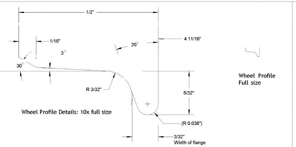
      Hi all think I am having a senior moment. I have been staring at the GL 5 drawing for wheel profile and don't quite see how to work from it without a lot of fiddling ?

      I see the measurement to establish the tread diameter, from the overall wheel size but no reference to where the inner radius starts?

      I see the with of "width of flange" ? which gives you a point on the 20 degree incline , don't see the point of this?

      What am I missing here please? I could draw it out to find the start of the inner radius, but shouldn't be necessary

      What is the significance of the tip radius i.e. 0.038?

      screenshot 2020-07-30 at 10.35.44 (1) - edited.jpg


      Am I over thinking this?


      Pete


      Edited By Pete White on 30/07/2020 13:28:59

      Edited By Pete White on 30/07/2020 13:30:51

      Edited By Pete White on 30/07/2020 13:31:49

      Advert
      #16184
      Pete White
      Participant
        @petewhite15172
        #488274
        SillyOldDuffer
        Moderator
          @sillyoldduffer

          This came up recently in another thread which I can't find! On second thoughts, oh yes, I can. Here – have a read. Should help.

          Dave

          #488436
          Pete White
          Participant
            @petewhite15172

            Thank you for your help here SOD and all the people who replied to the link referred to.

            Many good points made and I now have a way forward. I have been on Libracad and now know how far to machine in from the wheel face, at a distance in (5/32) from the wheel tip with a radius on the tool, then work on the taper until it "looks right"

            All help really appreciated, I was trying to work from the standard drawing !

            Still don't understand the radius on the tip being specified at 0.038? lol. I thought someone would know why and how to achieve it ?

            I will go and make some wheels now I think…………..

            Pete

            #488583
            Roger Best
            Participant
              @rogerbest89007

              Hi Pete

              The funny R0.038" is just a technical drawing convention for a radius, not a tool tip radius.

              It means that the radius of the wheel flange is 0,038", centred at the cross that the arrow points at. The brackets denote that it is a "reference" dimension, in other words the size that is generated by the other specified dimensions.

              Why is it in brackets when its so difficult to work out the shape from the information? – God knows!

              Edited By Roger Best on 31/07/2020 23:07:14

              #488589
              Paul Lousick
              Participant
                @paullousick59116

                Deleted

                Edited By Paul Lousick on 31/07/2020 23:23:15

                #488594
                duncan webster 1
                Participant
                  @duncanwebster1

                  I've only made 5"g wheels so the following is translated. Make a tool with a 3/32" rad and an approach angle of 20 degrees. Then off your CAD drawing find the diameter of a roller to put in the 3/32 rad, ie a bit bigger than 3/16" diameter and measure from this roller to the back face. Obviously drive the tool up the 3 degree slope with the topslide. Saddle locked. Then make the nominal 0.038" rad with your trusty file. Note the cross slide and topslide dial readings and make all the others the same. I use brazed carbide for this job. You don't want it going blunt hlf way through, although you can recover

                  #488618
                  Pete White
                  Participant
                    @petewhite15172

                    Thanks for the input both, the picture gets clearer. I like the roller idea Duncan.

                    I was expecting the drawing to be easier to follow. I can't remember having trouble reading a drawing before, but I have only been at it over 55 years?

                    Content apart I would have presented the drawing as a mirror image, as it would be made in the lathe?

                    I suppose this is a drawing of a left side wheel ?? !! lol

                    Pete

                  Viewing 8 posts - 1 through 8 (of 8 total)
                  • Please log in to reply to this topic. Registering is free and easy using the links on the menu at the top of this page.

                  Advert

                  Latest Replies

                  Home Forums Workshop Techniques Topics

                  Viewing 25 topics - 1 through 25 (of 25 total)
                  Viewing 25 topics - 1 through 25 (of 25 total)

                  View full reply list.

                  Advert

                  Newsletter Sign-up