Turning (approximating) a Domed Surface

Advert

Turning (approximating) a Domed Surface

Home Forums Workshop Techniques Turning (approximating) a Domed Surface

Viewing 8 posts - 26 through 33 (of 33 total)
  • Author
    Posts
  • #564628
    JasonB
    Moderator
      @jasonb

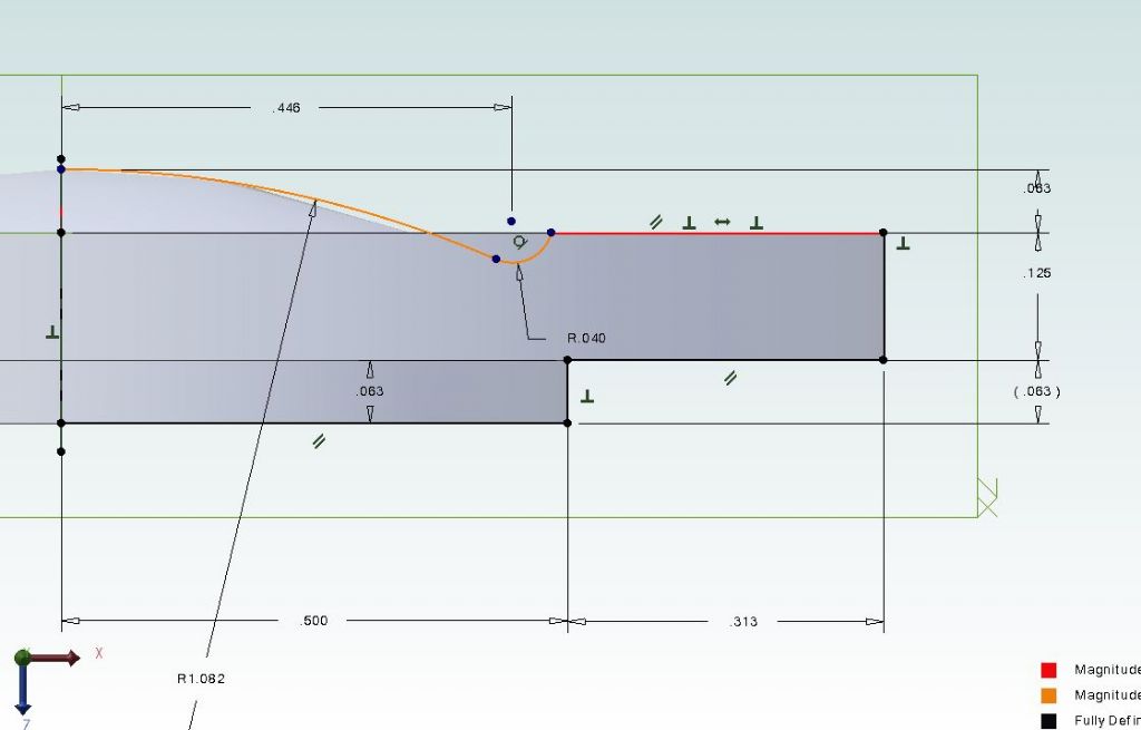
      If it's of use this is the profile I drew for the Victoria, radius and protruding

      vic cyl cover.jpg

      Advert
      #564692
      Dr_GMJN
      Participant
        @dr_gmjn

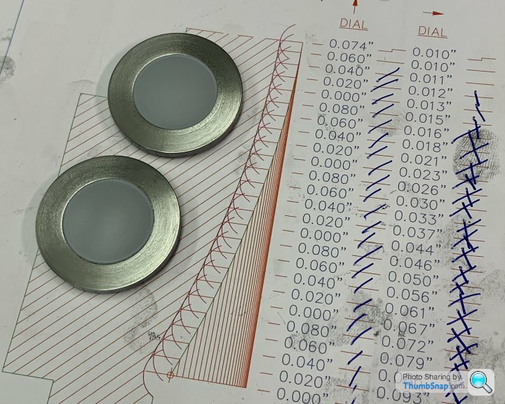
        Thanks Jason, I drew something out on CAD earlier, I think it will be OK. Just have to work out the co-ordinates. I think 25 increments of 0.020” on the cross slide should be good, using a 0.8 tip radius tool. Might need back-gear for this one:


        Couple of questions:


        1) The minimum section ends up at about 2.6mm. I say this should be OK to take the cylinder pressure. The original minimum is about 3mm, but I’d expect a large safety factor within that?


        2) I want to keep distance x to 7.5mm. Reason is that the front covers are that, and that dimension keeps the bolt PCD in the middle of the faced area. The angle of the tool tip means I can’t touch on the O/D and wind inwards by a set amount before going into the end. And I want that profile generated by the tip going in to form the edge of the dome. Any suggestions? Maybe start at the centre and work outwards – but that means determining the exact centre using the tip I guess.

        #564704
        JasonB
        Moderator
          @jasonb

          The 2.6mm will be OK and still likely to be more than the valve chest cover with it's recessed surface

          Make sure your DCMT insert won't rub it's edge to start with. 

          You will probably have to start from the outside and work inwards as the tool will rub on the smaller diameters if working outwards.

          I'd be inclined to rotate the toolpost further so that the edge of the tip nearest you is parallel of just beyond the axis of the lathe, you can then hold something against the edge of the cover and touch the tip against that as you wind the cross slide towards you and as the OD is known you can move 7.5mm in to the first cut

          Edited By JasonB on 29/09/2021 07:35:29

          #564745
          Dr_GMJN
          Participant
            @dr_gmjn

            Thanks Jason. I might turn the tip as you say, and might even draw out a starting geometry that I can rough machine out, to make sure the edges don’t rub. I guess you can see where the cutting edges end by looking carefully at the tip?

            #564754
            JasonB
            Moderator
              @jasonb

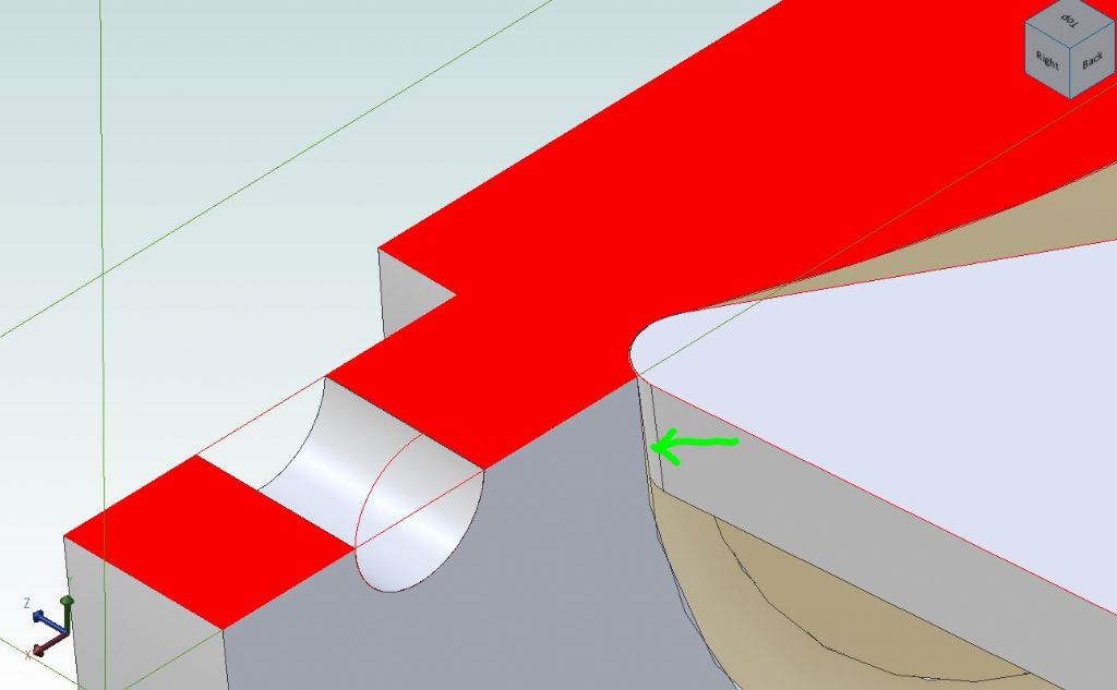
              Looks like you may just have enough clearance

              cover dcmt.jpg

              #564774
              Dr_GMJN
              Participant
                @dr_gmjn

                Ah, I misunderstood – tool rubbing on its flank, on the ‘I/d’ of the step?

                Do DCMT inserts have a standard flank angle (to stop rubbing) that you’ve modelled?

                Thanks.

                #564778
                JasonB
                Moderator
                  @jasonb

                  Yes, the C in dCmt signifies the angle which is 7degrees and by far the most common though others are available. This is why you see the insert boring bars tilting the insert at an angle so the side does not rub in a small bore.

                  #565573
                  Dr_GMJN
                  Participant
                    @dr_gmjn

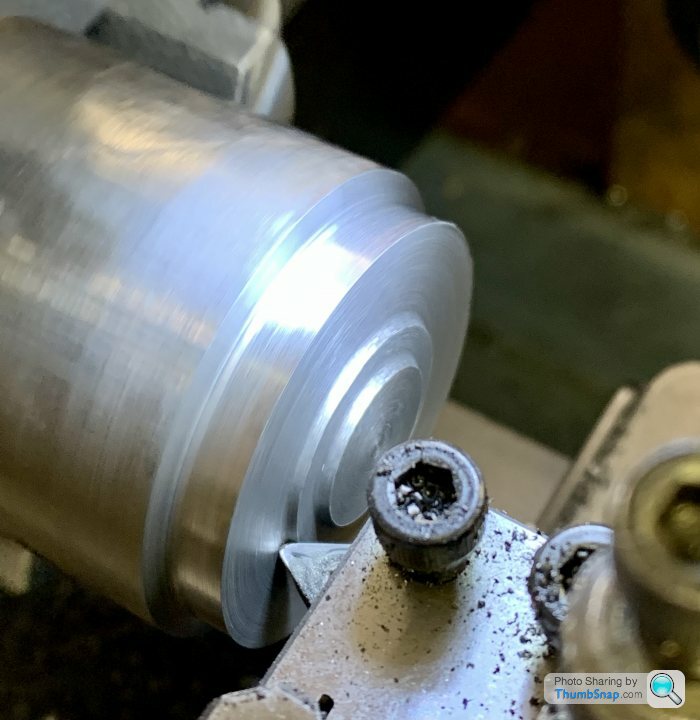
                    Just to wrap the thread up, I used the co-ordinate method. I used the side of the insert touched on the side of the blank cap, and the tip touched on the PCD face to get datums for everything:

                    Roughed the domes out:

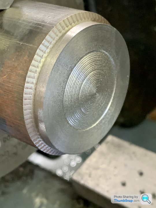
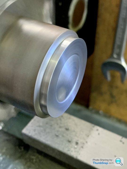
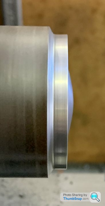
                    Then using co-ordinates, approximated the profile (nice example of chatter here – solved by using back gear). Also I made a slight error with a CAD measurement which showed up as the wide band. Didn’t make a deal of difference in the end though:

                    Then using a combination of a dremel, files and abrasive paper:

                    Smoothed to shape:

                    Parted off using the home made rear post from earlier this year (worked great):

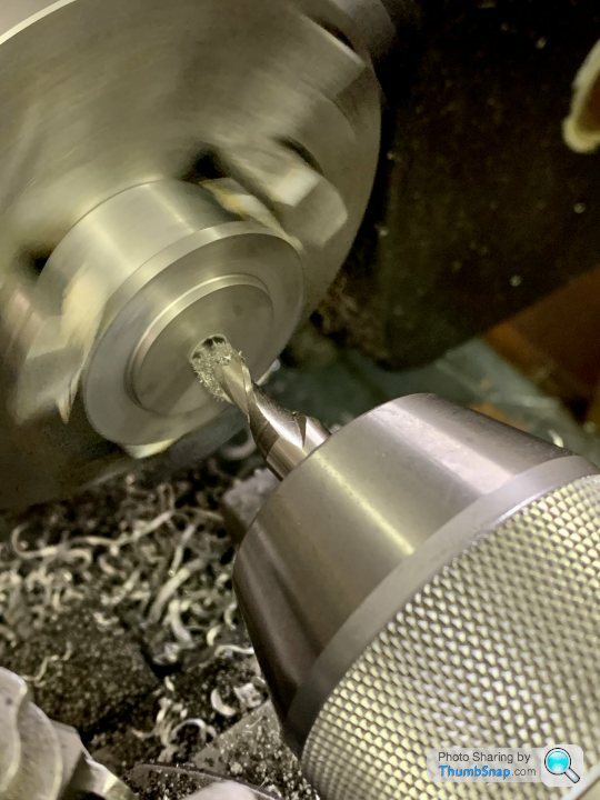
                    Then made a spacer ring and reversed in the chuck to turn and mill the inside details:

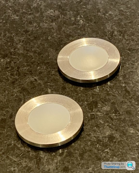
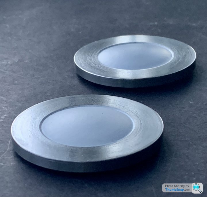
                    Took five attempts to get two good ones, mainly due to finger trouble, but eventually I got a decent result. As far as I can measure – with height gauge, callipers and more importantly, eyeballs – they are pretty much identical.

                    The domes are primed; they’ll be painted dark blue eventually.

                    Thanks everyone for the advice. Job done with your help – again.

                    Edited By Dr_GMJN on 04/10/2021 22:20:01

                  Viewing 8 posts - 26 through 33 (of 33 total)
                  • Please log in to reply to this topic. Registering is free and easy using the links on the menu at the top of this page.

                  Advert

                  Latest Replies

                  Home Forums Workshop Techniques Topics

                  Viewing 25 topics - 1 through 25 (of 25 total)
                  Viewing 25 topics - 1 through 25 (of 25 total)

                  View full reply list.

                  Advert

                  Newsletter Sign-up