TurboCAD Question: Accurate Printing?
TurboCAD Question: Accurate Printing?
Home › Forums › CAD – Technical drawing & design › TurboCAD Question: Accurate Printing?
- This topic has 81 replies, 16 voices, and was last updated 26 June 2024 at 00:13 by
Nigel Graham 2.
-
AuthorPosts
-
13 May 2024 at 10:14 #730396
David Jupp
Participant@davidjupp51506Nigel – how did you transfer the TurboCAD drawing to Alibre?
If as DXF or DWG it should have maintained layers from the original. You can turn off visibility by layer to make it simpler to work with an individual part. There are some other editing tricks that can help.
When working with 2D CAD from another system, I typically use a mixture of modelling from scratch in Alibre, and copying figures from the DXF to re-use in my 2D sketches (often a profile that I’ll use in a revolve).
Beware though – my own experience is that 2D files from external sources are often less than perfect, and will require some repair to give valid closed profiles. Also any ‘symbols’ / ‘blocks’ will need to be exploded before trying to use in Alibre.
You have my details if you want to send over the file.
To get back to your need to print A3 sheet – does your A4 printer offer a ‘Tile’ or ‘Poster’ print ? – or is there a utility from HP that will do that. May not be perfect, but could be good enough to get started.
If you create a PDF – Adobe reader allows you to print the image over multiple sheets.
13 May 2024 at 12:33 #730417 JasonBModerator@jasonb
I suggested sticky tape and multiple A4 sheets early on, does not really even need a “tile” option on the printer.
Michael, I thought the whole reason for the thread was that Nigel wanted to print actual size. Having to move an image about on a small ipad screen is likely to be less appealing that moving it about on his existing PC screen.
If you are suggesting he take the ipad to the workshop then does the ios open DXF and DRW files OK ? Nigel would also have to start learning the apple way as well but I’m sure you could answer all his questions. However he would probably be better off with a cheap laptop which would allow him to use something he is familiar with (windows) and it could also run Alibre and possibly his old Turbocad and open the files on a reasonable size screen in the workshop.
13 May 2024 at 13:33 #730436 Michael GilliganParticipant@michaelgilligan61133
[…]
Michael, I thought the whole reason for the thread was that Nigel wanted to print actual size. Having to move an image about on a small ipad screen is likely to be less appealing that moving it about on his existing PC screen.
If you are suggesting he take the ipad to the workshop then does the ios open DXF and DRW files OK ? […]
and I thought that reason was getting lost in obscurity now that his A3 printer is dead.
Yes, with some Apps an iPad can be persuaded to open most things … but my thought was really that Nigel might save the file to PDF from TurboCad at the “printing” stage.
I’m honestly not bothered what Nigel chooses to do … I offered “Just a thought”
MichaelG.
.
Incidentally, my little 9.7” diagonal screen has a resolution of 2048 × 1536
… which does make it kinda useful for scrolling through an ‘A3’ PDF, then pinch-zooming as appropriate.
Nigel is welcome to contact me, but unless he does, I shall refrain from making any further comment on this Topic.
13 May 2024 at 13:41 #730438Nigel Graham 2
Participant@nigelgraham2I don’t want to “stay locked into” anything – just to use the best method available to me!
Nor do I want yet another computer cluttering up the place or adding to the load on workshop wiring that looks suspiciously like a 13A spur. I’ve too much “stuff” in the house and workshop now.
.
I don’t know about “Tile Printing” but could copy overlapping sections of a drawing to blank jpg files, and tape or glue their prints together. I have used something like that once before, with an image that sprawled along the length of four or five separate A4 sheets glued end-to-end.
The difficulty is ensuring the annotations are legible and do not cross the margins. There is also a danger the different prints will not connect properly and may be of different “scales” that might not even be symmetrical.
‘
I experimented but cannot see how that drawing can possibly seed 3D models. It is too complicated, and probably has many elements in their wrong layers, accidental ‘Workplanes’ that act like Layers, and other hidden obstacles. I intended it as orthographic-only, not to base a 3D CAD image impossible for me to create anyway!
Besides, how can you design a machine’s components before a General Arrangement from which to draw them? But how do you create a GA without knowing the components’ basic shapes and sizes?
To break that circular illogicality I made that GA by designing both the parts and their layout together, from a few key dimensions; and it can only be in dimensioned, 2D elevations.
I’d need draw each component alone completely from scratch, guided by the 2D GA. On the other hand, why not skip that intermediate 3D stage of increasingly questionable value, and make its workshop drawing directly from the GA?
.
I don’t know what those diagonal crosses on the eccentrics are. They appeared when I copied the drawing across.
There no Blocks in the drawing. I don’t know if ‘Blocks’ are something to do with 3D work, but the tool-bar sign implies they are related to the ‘Explode’ tool that irreversibly breaks figures into separate lines. So are dangerous to try!
13 May 2024 at 14:05 #730442David Jupp
Participant@davidjupp51506Nigel,
A ‘symbol’ or ‘block’ is a collection of figures (lines, arcs etc.) that have been combined into a single entity. You can think of it as grouping items together – it is quite common in AutoCAD and other 2D CAD as a time saver if something like (say) a nut will appear several times in a drawing.
It needn’t be ‘dangerous’ to try explosions – you still have the original file (or you can save a copy before any step), so you can always go back.
If trying to develop a part from existing 2D GA, my approach (having decided which part or parts to tackle) would be along the lines of
- Either delete items from drawing, or send to layer that can have visibility turned off, leaving those figures relating to the target part.
- Think about how I might use the figures in 2D sketches. Might use all of some figures if creating an extrude boss. If doing a revolve, I might add a centre line and trim away half the outline.
- Copy required items, paste into part 2D sketches, doing a sketch analysis to find gaps, overlaps etc.
Some aspects may well be faster/easier to do directly in the 3D part model, it’s only worth pulling across that which makes things easier.
Sometimes it is just as fast (or faster) to refer to your existing drawing but do all the modelling from scratch.
If you send me the file and put a red line around a part (or highlight it in some other way) I’ll have a go at using the file as starting point for a model. As I’m not familiar with your design, I may have to ask the odd question. If I succeed, I’d send you the result and post a short ‘how to’ here.
13 May 2024 at 14:11 #730445David Jupp
Participant@davidjupp51506I have worked from 2D CAD versions of many 1970s era designs in the past. I often find that for a lot of the modelling it can be quicker to start from scratch, but I have regularly lifted profiles of turned castings from 2D CAD, added a centre line and trimmed to that to give the sketch for a revolution. Can be quicker than defining all the angles.
13 May 2024 at 16:49 #730488 Gary WoodingParticipant@garywooding25363
Here’s an extract from the TCAD User Manual.
Simple Printing and Tiled Printing
To make a simple print of a drawing that fits on one sheet:
Select File / Print to open the Print window.
For Print Range, click All to print your entire drawing.
Check Fit on 1 Page.
Select the printer, and click Properties to set the paper size and orientation.
Return to the Print window, and click OK to print your drawing. Your drawing will be centered and printed on a single sheet of paper.
If your drawing is larger than the printer sheet, as it is in most cases, you need to use tiled printing. This method prints sections of your drawing
on separate pages, which can then be pieced together. The Page Setup is used to set parameters for tiled printing (see Page Setup).
Tip: When tile printing, it is usually best to turn the Print Crop Marks option on, unless your printer is capable of printing with zero margins.
Crop marks enable you to easily trim the edges of the paper so that the sheets can be pasted onto a backing for display.
An example of tiled printing is as follows:
Select File / Page Setup.
On the Paper page, use the Printer Paper field to specify the paper and orientation.
In the Drawing Sheet Size fields, specify the size and orientation of the area on which you want to print the drawing. For example, if
you want a printout 2 feet tall and 3 feet wide, you would type 2 ft x 3 ft in the list box, and choose the Landscape option. Or you can
select a standard size.
Click Fit to place your drawing on the tiled sheets.
Click Print to print your drawing immediately, or click OK and print later using File / Print.
Another way to tile print is to specify the number of rows (the number of pages from top to bottom) and columns (the number of pages from left
to right). This is done on the Layout page of the Page Setup. You can then return to the Paper page to fit your drawing onto the tiled printer
paper. TurboCAD will automatically adjust the dimensions of the drawing sheet to accommodate changes in the number of rows and columns.13 May 2024 at 17:26 #730499Nick Wheeler
Participant@nickwheelerI experimented but cannot see how that drawing can possibly seed 3D models. It is too complicated, and probably has many elements in their wrong layers, accidental ‘Workplanes’ that act like Layers, and other hidden obstacles. I intended it as orthographic-only, not to base a 3D CAD image impossible for me to create anyway!
Besides, how can you design a machine’s components before a General Arrangement from which to draw them? But how do you create a GA without knowing the components’ basic shapes and sizes?
To break that circular illogicality I made that GA by designing both the parts and their layout together, from a few key dimensions; and it can only be in dimensioned, 2D elevations.
I’d need draw each component alone completely from scratch, guided by the 2D GA. On the other hand, why not skip that intermediate 3D stage of increasingly questionable value, and make its workshop drawing directly from the GA?
Before reading that, I wouldn’t have even considered creating a General Arrangement before any of the components represented within it. The whole thing would be started from a fundamental, fixed feature like the crankshaft axis for an engine(it’s going to be needed for lots of features), track wheelbase and ride height for a vehicle, spindle axis or required work envelope for a machine, mating features of already existing components, etc etc.
Surely a GA is the last thing to do, the pretty colour picture to put on the cover of the folder containing the useful information? It’s largely irrelevant for a 3D CAD assembly when you can display the entire model, or as many faces, cutaways, sub assemblies or isometric views detailed as you think necessary at any time, for any process, with a few mouse clicks. And those are all much easier if you haven’t hobbled yourself with a flat drawing….
13 May 2024 at 19:37 #730517 JasonBModerator@jasonb
I asked Nigel to send me the file with the arrangement of his wagon’s engine, he sent it as the Alibre drawing file he shows in his earlier images.
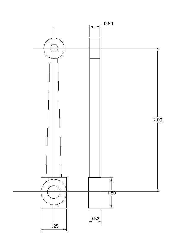
To show that rather than being useless the imported 2D file can be used to produce the 3D parts without having to start from scratch I picked one of the two conrods which are at the far left of the image.

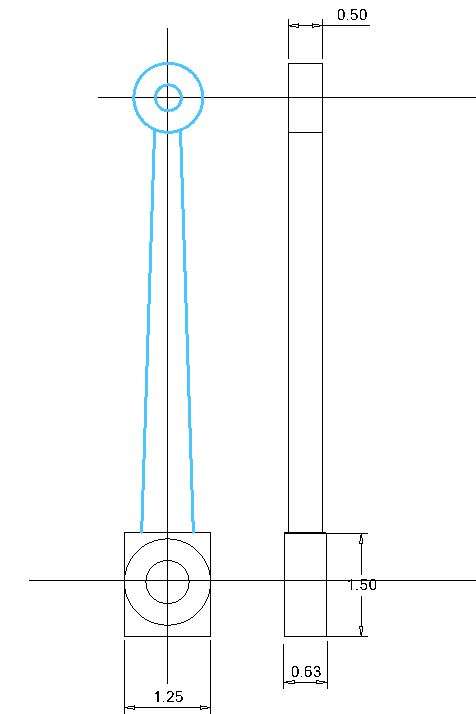
Firstly I clicked “activate 3D Sketch” which is top left of the screen and then while holding down the shift key clicked on some of the lines, circles etc which turned them blue. I then clicked copy which put these blue lines into my clipboard.

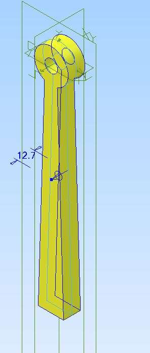
I then opened up a new part file, clicked activate 2D sletch and clicked the plane I wanted to sketch on, in this case the XY plane. I then selected the “paste Stamper” and pasted the copied items to start the sketch of my part. I had to add a line to join the bottom of the tapered lines to close the sketch and also trim the unwanted part of the larger circle between the two tapered sides for the same reason (See later comments)

I then extruded this sketch mid plane to 0.5″ wide as per the dimension on Nigel’s file. I could also have taken other dimensions off his file if they were not shown

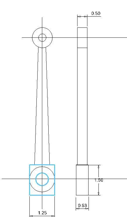
I then basically repeated the process for the big end, copy the rectangle and circle

Paste as a second sketch in the new part file, I also added the 7 “dimension to make sure it wa spasted in the right place.

Then extruded about the mid plane to 0.630″ wide

And there you have the basic conrod, I have not had to redraw or size the basic shapes, just put in a dimension for the extrusions.

However having been able to look closely at the imported drawing there are quite a lot of issues with it that would probably mean it is better to start again modeling the parts from scratch. A couple of examples follow:
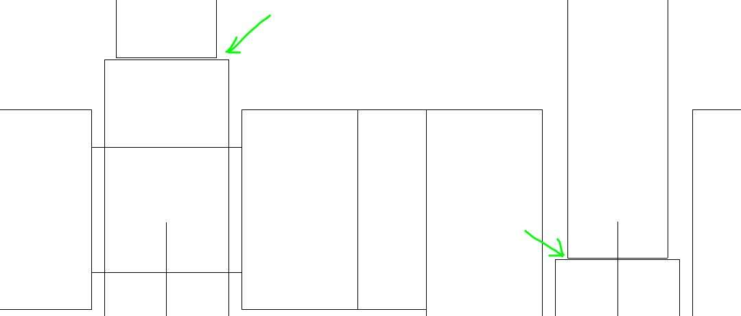
This is where the tapered part of the conrod meets the big end rectangle there are twin lines and they are different either side, I don’t think these are specific features more just an issue that was on the original Turbocad drawing that has followed over.

And when looking at them on the section through the assembled engine they are different again with the tapered rods not even connected to the big ends

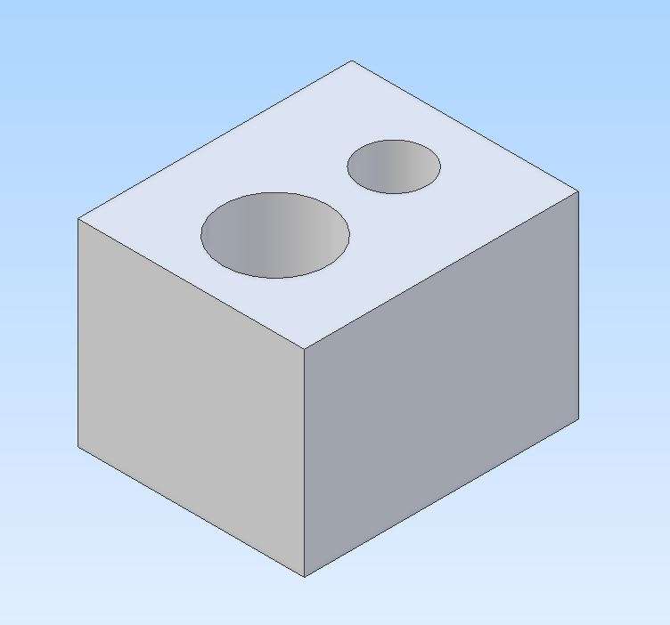
Lastly similar done with the basic cylinder, rectangle and holes copied and then pasted & extruded
 13 May 2024 at 20:12 #730519
Nigel Graham 2
Participant@nigelgraham2Thank you All.
Our messages have crossed somewhere. That analysis of my drawing arrived while I was typing this. I knew you’d find it full of mistakes!
Jason – I’ve taken up your offer but please note it might not arrive. I have had strange e-post problems, with messages losing attachments or even themselves, in either direction. I think it easiest to let you decide which area of it is most likely to “work” .
…..
I’d always understood that designing anything complicated needs some sort of general-arrangement drawing, even if that does start as a skeleton of centre-lines and a few basic outlines.
I’d assumed the same principle with CAD: you need something to guide drawing the components.
You can’t design, say, a simple lathe headstock casing unless you know the shapes and sizes of the spindle, back-gears and bearings and the space they occupy when put together; but you still need something to anchor all the parts to, such as the width of the bed and spindle height. And if that something is not a general-arrangement or least the sub-assembly, what is it?
People often point out an advantage of CAD is helping you to determine clearances etc., but this needs a full assembly-drawing, and this is where I hit the hen-and-egg argument. How do you know this or that will revolve without hitting anything, or that those two gears will mesh properly, unless you know how much space is available before you draw them? (I only ever draw gears only as pitch-circle wheels.)
.
I realise a skilled user can go a lot further more rapidly with a CAD 3D model; as creating those auxiliary views etc. manually is difficult and very time-consuming.
So I see the general-arrangement as more than merely the brochure picture (a carefully-tinted etching in the 19C!) but a fundamental design tool – however it is drawn. My vehicle GAs – two or three of them – are drawn in TurboCAD from measuring the object so far, but I made some preliminary drawings from the archive photographs right at the start.
…
I think in summary I have met my natural maximum learning of CAD but the two systems I have offer me very different things so they are complementary not competitors:
TurboCAD is good for orthographic component and assembly drawings, and geometrical constructions.
It can be used to construct very high-grade, very complicated 3D models but I can’t progress beyond an absolute basic level, and I do not know how to obtain elevation drawings from even a simple 3D model of a single part.
It also contains some horrendous traps and these can unexpectedly and irreversibly, ruin your work.
It is also very poorly documented, and its on-line “help” manual is the worst technical writing I have ever seen: poor layout, no proper index, and being a pdf document the screen-page numbers and physical page numbers rapidly go far out of step. One of TC’s professional users, Don Cheke, used to make advanced training-exercise videos for already fairly-experienced users but I think he’s retired. Paul Tracey made introductory pdf manuals but I don’t know if he still does.
.
Alibre Atom lets me draw single, geometrically very simple, parts but I still sometimes need create a lot of geometry even just to place a couple of lines. I can even Assemble a few Parts – if I’ve somehow accidentally drawn the parts so they point the right way when imported.
It is easier in many ways than TurboCAD. Even I can produce very simple 3D images and turn them into dimensioned elevation drawings good enough for me; but for Assemblies I always make many orientation, plane and constraint mistakes without knowing how.
It is well-documented and comes with various pdf-type tutorial exercises – though I realised I was following them rather blindly, without really understanding what I was doing.
Nevertheless, as with TurboCAD, I cannot expect to be able to produce full Alibre 3D images of complete machines.
13 May 2024 at 20:54 #730523David Jupp
Participant@davidjupp51506What you can do easily in 3D CAD is start with an empty assembly and add in say a couple of axes, and a plane or two – these for example representing spindle, back gear shaft, top of bed based on what you believe to be the driving dimensions.
After adding a few parts, you can even adjust the axes positions if needed or desired. It is simple to try a few alternatives. You can then design the headstock casting around the internal parts.
13 May 2024 at 20:56 #730525 JasonBModerator@jasonb
I’m still not averse to doing a quick freehand sketch to get a feel of a general layout before starting with teh CAd, really depends on the particular item.
If it is from a photo, sketch, patent drawing or etching thes edays I am just a slikely to import one of those images into Alibre and scale the image to the size I want to build at which may be based on a flywheel diameter or cylinder bore.
Once I have done that I’ll simply sketch a series of lines over that image which gives me the actual length and I can then base my sizes of parts on those.

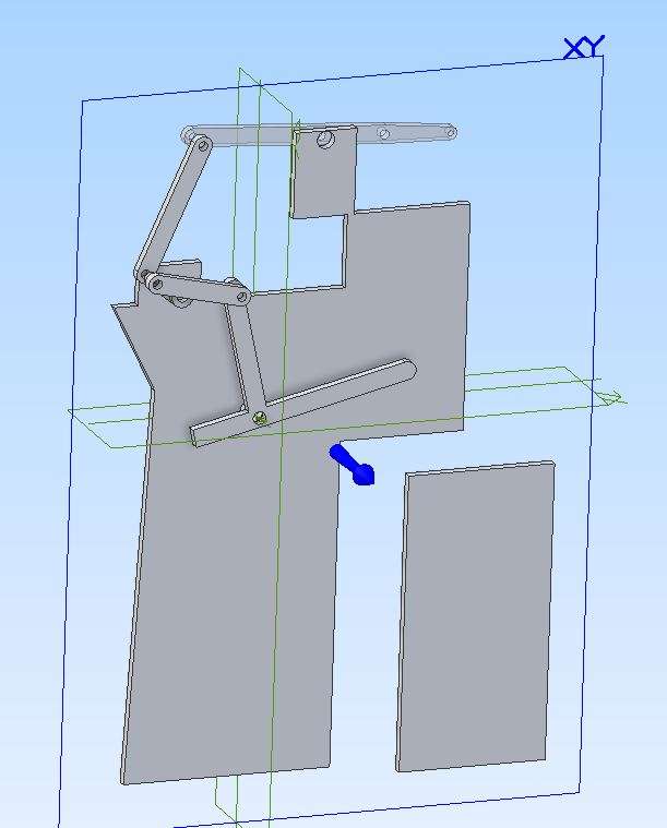
I may not fully detail the part to start with, on the engien above which has a lot of linkages I first sketched them out as not much more than lolly sticks with hole splaced from the sizes obtained. Then assembled them on a rough frame that had the larger castings just drawn a srectangles.

This gives me enough to see how things move
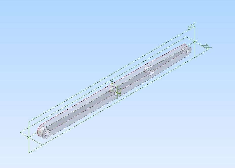
From there I will then start to detail the individual parts so what started as the top beam sketched like this

Ends up like this after many tweaks and alterations that are needed as more parts are added and issues arrise

Until I have all the parts modeled, assembled and tried for movement which can still be overlaid onto the original image
 13 May 2024 at 22:34 #730540
Nigel Graham 2
Participant@nigelgraham2Interesting! I didn’t know you can draw over an imported image such as a patent specification.
You say “tried for movement”. Nor did I know you can animate the drawing, but having watched that video now recall one of Alibre’s tutorials has you draw what might be described as an “executive toy” then rotate its handle.
.
I don’t know why that connecting-rod had those strange breaks. I’d probably drawn them as separate pieces but not assembled them correctly. The stray line could have been anything but was probably left from some change I’d made. Unless you magnify the display you don’t usually see things like that.
It’s also very easy to have such oddments lying directly below outlines, and they prevent moves like Extrude or (in TC) Join Polyline working. Fortunately the selection highlighting will reveal the little varmints so you can delete them.
I’ve found an equivalent in Alibre: minute black dots on the screen that magnifying reveals as teeny-weeny line trimming fragments sometimes quite a distance from the outlines. I am not sure how they happen but they prevent switching from Sketch to Model.
.
David –
I see what you mean. Whenever I’ve drawn anything manually I’ve normally started with the main centre-lines and perhaps some major element like a big rectangle or circle.
…
The main problem I have found with having to design from a lot of assumptions and “missing-links” is that it is very easy to make the wrong assumptions.
For example, I knew that the chassis rails of my wagon have to bend inwards then turn back parallel somewhere in the region of the engine and boiler, to support the latter and to give room for the front wheels to steer.
I studied the many works drawings in Maurice Kelly’s book on overtype steam-wagons to assess how to go about this, but the variety left me none the wiser, really.
Consequently I am now lumbered with trying to install the transmission-gearing below and inboard of the narrowing frame rather than where that is still full-width and parallel. It is also constrained by the line of the driving-chain, which is further inboard than it ought be due to how I made the axle and differential.
Though I think I had drawn the chassis I could not predict quite how and where the mechanism would really fit.
Yet unless I had tried to draw the basic layout first I would have had nothing to guide me.
14 May 2024 at 07:31 #730553David Jupp
Participant@davidjupp51506Nigel – that’s the really big benefit of 3D CAD.
Yes you start of with some assumptions/guesses. When you find out as the design develops that some of those initial guesses need to be adjusted, it is relatively easy to do without having to start from scratch.
I once did a project for a commercial builder of bodies for lorries – the basic design had to fit on several different chassis – some had flared chassis rails as you mention, some didn’t, the location of the flare varied, as did overall body length.
The finished design was driven by about 6 numbers – a quick edit of the numbers, then go for a cup of tea whilst all the parts regenerated was all that was needed to adapt the design to a different vehicle. Then the 2D drawings were refreshed from the model, were printed and passed to the fabrication shop.
14 May 2024 at 09:11 #730569IanT
Participant@iantA very useful example Jason – thank you for taking the time to explain it.
I have to fill in some ‘gaps’ (missing valve gear) in a locomotive I’m building, which came as a ‘box of bits’.
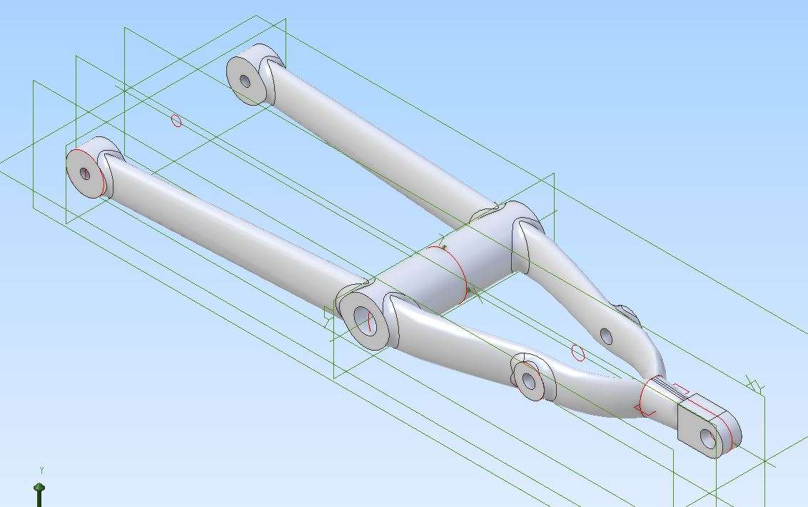
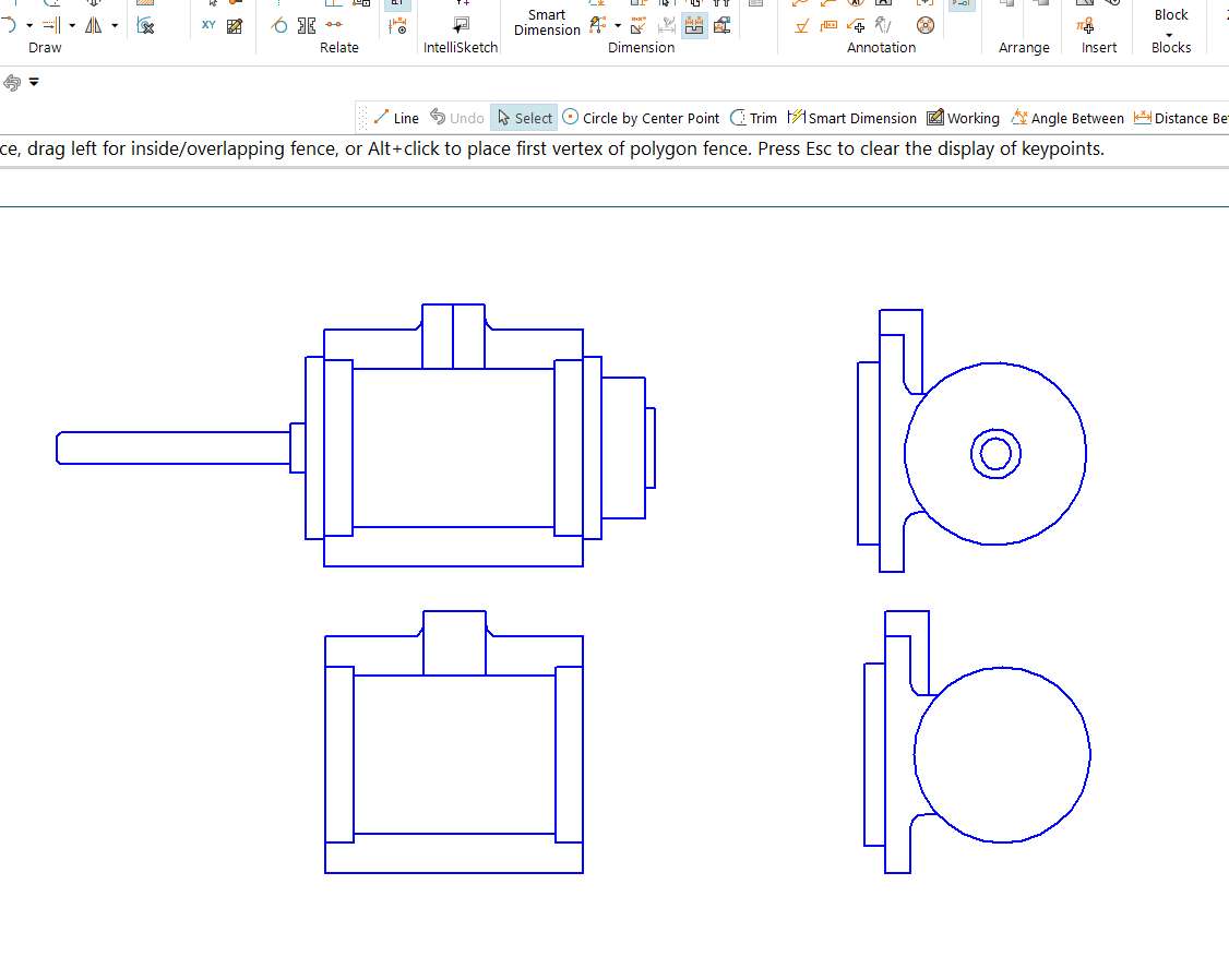
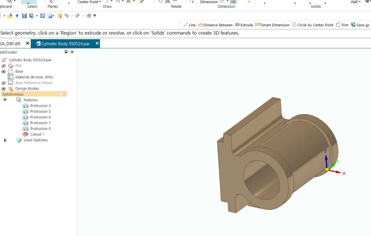
I was not able to find any published drawing for the engine and originally drew the parts I did have out in 2D (TurboCAD) but didn’t take it any further at the time. I was away on holiday last week and spent a couple of evenings moving parts over to Solid Edge. There’s a utility in SE to convert 2D drawings into 3D parts but I decided to stay within my comfort zone by importing the DXF and then extruding one view, using the other projections to provide dimensions and decide the extrusion extents. Hard to explain but this is the before and after on one of the trickier bits…the cylinder (frames and other parts were very easy to do)


I was somewhat stalled on the missing valve parts but will use your idea of building a simple ‘stick’ assembly to get the over dimensions sorted before jumping into finished parts and assemblies.
Regards,
IanT
14 May 2024 at 10:34 #730584SillyOldDuffer
Moderator@sillyolddufferNigel’s comments on his need for a General Arrangement drawing (I agree), highlight why design from first principles is difficult. Everything depends on everything else, or as Nigel puts it ‘chicken and egg’ situations. In order to progress, the designer usually has to make a series of intelligent guesses. Note the risk that a guess might be wrong, in which case the whole design might have to be revisited because an early misjudgement causes the whole arrangement to unravel. However it’s often possible to fix things by altering a few components.
I suspect bent chassis rails are an example. As straight rails are easier to make, most designs would try them first. But later, something else might require them to be bent. Extra room might be needed for the steering wheels, or the engine might need better support, or space for a differential. So a bent chassis rail suggests the designer had to think again.
In the worst case the designer is faced with a multitude of components, any of which can change size or position, at any time as the design evolves. 3D-CAD is extremely helpful because all the components are modelled individually, and as an assembly. The computer spots collisions and misfits etc, and makes it easier to modify whatever needs to be changed. Of course the designer has to learn how to drive the CAD package!
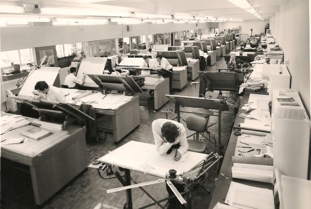
Exactly the same process was done by Drawing Offices, but this was labour intensive and incredibly slow whenever several components had to be redrawn. Picture is of the №2 Drawing Office, with 36 drawing boards.

Part of the design process is reducing the amount of guesswork. A very good way is to maximise use of standard components, allowing the Lego Blocks or Meccano parts to steer how the whole comes together. Doubt that’s possible with Nigel’s project, so we’re forced into a full-blown design, unless information can be extracted from history as demonstrated by Jason. Getting the approximate dimensions and positions of the main components saves an enormous amount of time, and any subsequent guesses Jason has to make are well-informed.
Otherwise, the goal is to specify, by drawings or CAD model, the assembly and shape of the whole machine and the form and dimensions of all the sub-components:
- First understand the required functions and characteristics of the machine. Many engineering projects come to grief because the requirement stage is skimped or assumed.
- Quantify as many facts as possible: main dimensions, weight capacity, weight limits, turning circle, speed etc.
- Do a preliminary design. I start with hand sketches on squared paper, perhaps spending a lot of time scribbling and tweaking before tidying them up in 2D or 3D-cad. Originally I used 2D a lot, more recently I’ve found it more productive to go straight to 3D. At this stage don’t tackle detail, for example a road-wheel can be represented by a simple disc, avoid getting into spokes and bearings!
- Next add detail, for example turning the simple disc representing a wheel in the preliminary design into a real wheel with a hub, fixings, and a tyre. Connecting the wheel to an axle requires development of a bearing that fits both, and probably a universal joint and some sort of suspension. Several iterations may be necessary.
Where to start a design is a good question. With something that’s not going to change much! Then the rest of the design can develop from it. In the case of a steam tractor I guess it’s the engine, boiler and drive train. The original steam tractor will have been required to pull a certain load at a certain speed, which decides the size of engine needed. Then the firebox has to be accessible from the cab, and ideally the weight should be distributed directly over a wheel pair, or between two wheel pairs, and positioned to provide a low centre of gravity. Easiest I guess to put the boiler and engine behind the cab, either on, or slung between low chassis rails. Ideally the chassis rails should be wide apart and straight, but they can be bent to make room for steering etc. Once the chassis rails are decided, the steering and drive wheels can be added, with suspension to fit, and I’d probably finish with the deck, cab, controls and bodywork.
It’s all hard work!
Dave
14 May 2024 at 15:50 #730652Nigel Graham 2
Participant@nigelgraham2I do have the advantage that my project is not totally free-lance, so I have a fair amount of basic information. Unfortunately some key details are unobtainable.
That includes the true shape of the chassis, partly obscured the photographs by what can hardly be called “bodywork”. So I know the rails were directly above the rear springs then necked inwards at the front to accommodate the steering; and front-view photos gave the proportions. The difficulty was where to double-bend the rails. These are of 50 X 25 X 5mm hot-rolled steel, so to scale overall and although perhaps over-scale thick, do seem to replicate the original material. I bent them cold, using a “jim-crow” made for narrow-gauge railway work, and it’s unlikely I could have done that if the bends were tighter and close together. They would have had to be cut and welded.
‘
The thickness also allows tapped screw-holes, avoiding awkwardly-placed nuts that would be invisible anyway. This is part of my principle from the outset that large units like the bunkers can be removed reasonably easily with minimum disturbance to anything else. The bunkers as a pair, with the front panel, are a complete lump held by a few hexagon-headed screws through their floors, to tapped holes in the chassis. No pipework etc, fastened to them. Just ‘cos it’s a road vehicle it doesn’t need the modern rule that the smaller and simpler the repair, the greater and more difficult the access dismantling!
.
So I am trying to muddle through some sort of middle-ground, back and forth between component and assembly drawings but having to draw components twice: once on their own and once, simplified a bit, on the assembly-drawing.
Though manually drawing assemblies necessitates creating all, even repeated, parts individually, I even have to do that in TurboCAD as well. It’s harder still if the copy needs partially rotating, like a connecting-rod at half-stroke next to its brother on dead-centre.
Alibre’s approach to assemblies is far easier; multiple copies and all, though I still find it very difficult.
So I have not tried to create any sort of 3D general-arrangement or sub-assembly drawing for this project, because I certainly can’t in TurboCAD and don’t believe I can in Alibre.
11 June 2024 at 01:03 #735310Nigel Graham 2
Participant@nigelgraham2Still caught out by that blasted ‘Viewport’ thing!
Do everything right, you think, umpteen menus and all… and it might print at the size you set, but only if it feels like it.
.
I need an actual-size, 2D drawing of a fairly involved assembly so measured the metalwork for a pencil sketch from which to create a single-view TurboCAD drawing.
It took two attempts despite carefully ensuring all the correct settings. The dimensions transferred to the first print showed the right numbers, on under-size distances.
The second attempt worked with a Paperspace viewport as large as the image of the paper itself; by guesswork and probably sheer chance.
.
(Dimensions in TC are normally inert, but can be set to follow object size changes. They cannot be used to change the object.)
……
[TurboCAD allows the direct, simplified orthographic drawing appropriate for the task in question. ]
11 June 2024 at 15:04 #735431SillyOldDuffer
Moderator@sillyoldduffer…
So I have not tried to create any sort of 3D general-arrangement or sub-assembly drawing for this project, because I certainly can’t in TurboCAD and don’t believe I can in Alibre.I think Alibre is capable. Nigel’s problem may be expecting too much too soon of the software attempting difficult tasks before enough basic CAD has been mastered. Lots of time wasted trying different tools in hope one them will make it easy, rather than tackling the steep learning curve. A change of approach may help.
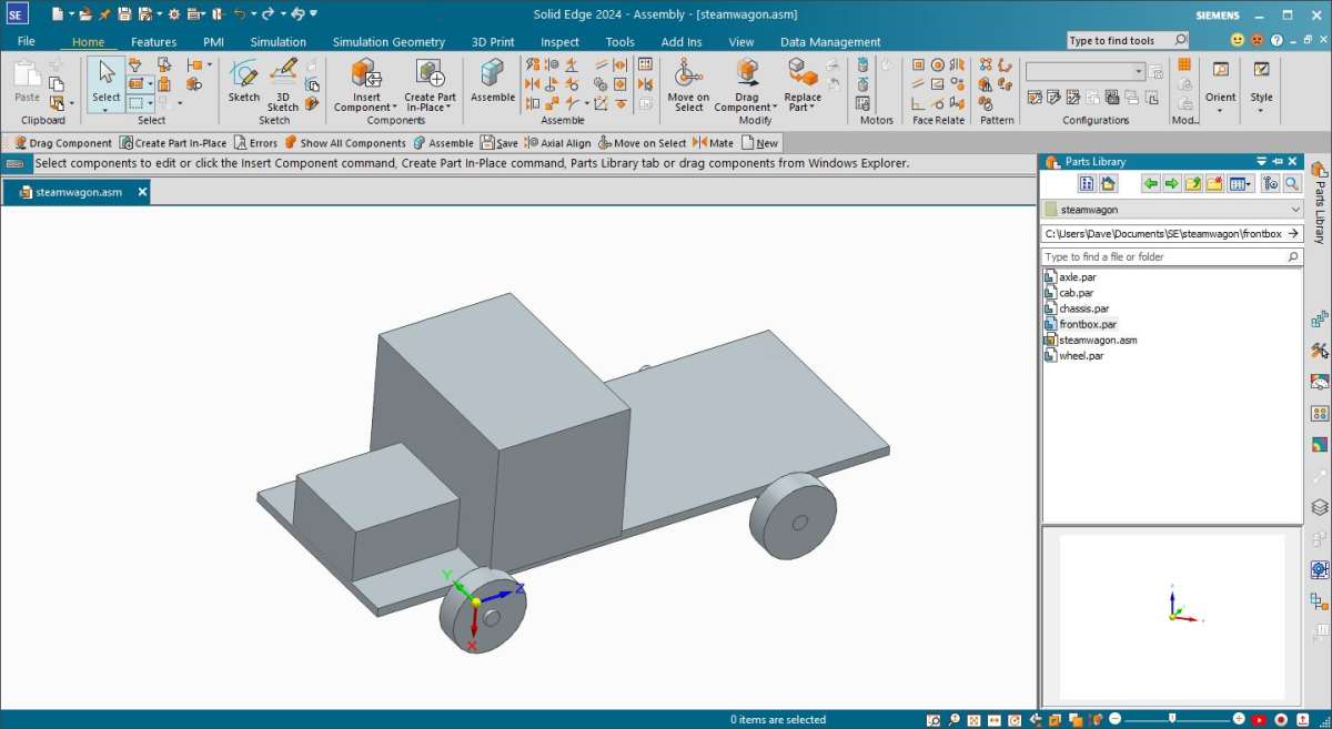
Here’s a general arrangement of the Duffer Steam Wagon I knocked up this afternoon. It’s an assembly, very deliberately kept as simple as possible. It’s purpose is to identify the main dimensions of the layout, and avoids a great deal of work by ignoring detail. The wheels are discs, the axles are rods, the chassis a platform, and the bonnet and cab two boxes. It concentrates on the bare essentials.

The model isn’t a drawing. It’s an assembly of 5 simple 3D models: wheel, axle, chassis, frontbox and cab. At this stage they and the assembly only represent the outline, but they are all dimensioned, and can be changed.
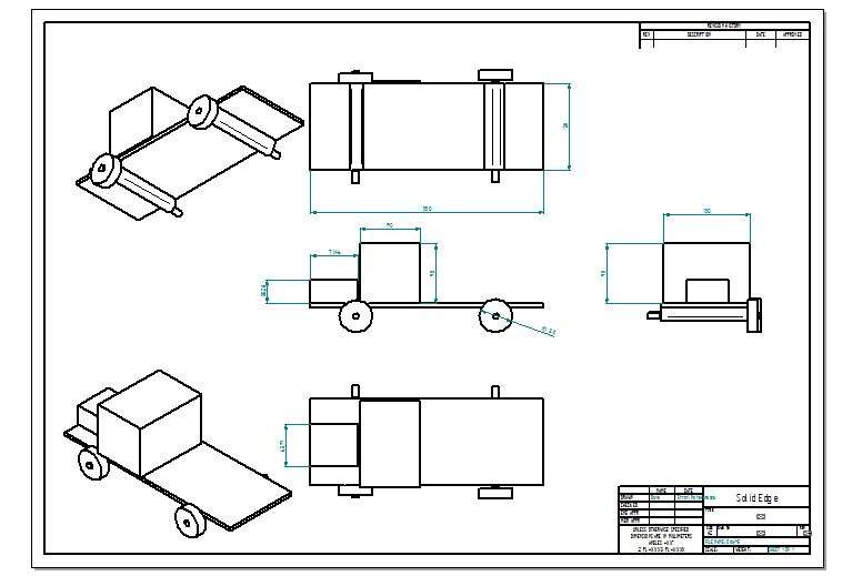
If required, a 2D drawing is generated by the software from the model, either of the whole assembly or the individual parts.

Step 1 of the design is to manipulate these very simple parts to get the overall proportions and placements about right. At this stage, even though they might be known I would ignore details like the cab doors and windows, and position of the chimney etc. They waste time when the important thing is establishing the initial GA. Save adding details for when the individual parts are refined later, perhaps right at the end.
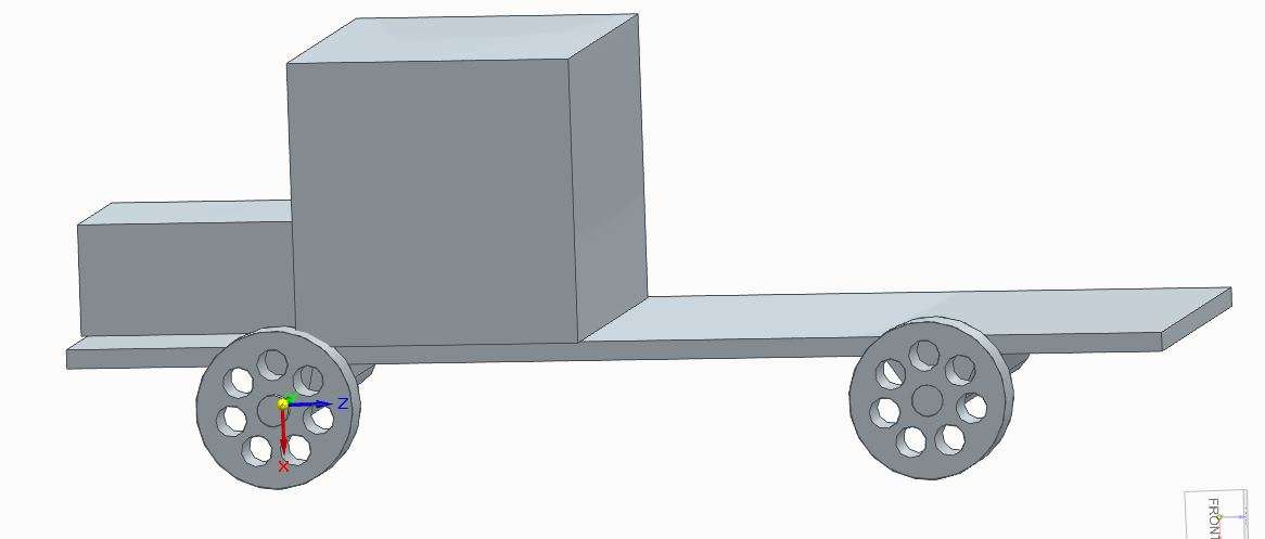
Just as an example though, my current design uses the same wheel throughout. As the wheels (only two fitted, but could be 4), are all derived from the one object, changing the wheel object automatically updates the assembly.

Much like a real steam wagon, my 3D CAD assembly consists of parts that can be updated later. Potentially, I could take this crude starting point all the way to a fully polished design. The block approach means progress can be made without me having to design anything in full, in fact it’s best to defer detail design for as long as possible. When I come to add wheel details such as a bearing and connection to the axle and suspension, provided it fits into the space available, the rest of the design still works. Fairly obviously adding the suspension will change the chassis, as will the prop shaft, but that shouldn’t upset the cab and bonnet significantly.
I didn’t need to draw a GA by hand, rather I created one on the fly direct in 3D based on guessed dimensions. I started with a wheel, added an axle, then the chassis, and finished with a couple of boxes! Working with blocks avoids the time it takes learning how to CAD model detailed objects: that joy can be saved for later.
Although CAD makes it easy to start with block representations of parts that are refined later on, which pays off big time as the project grows, the same block approach can be done with pencil and paper or balsa wood and cardboard. Less efficient than CAD because it takes longer to change, but no need to learn to drive a CAD package. Not everyone gets on with CAD!
Dave
11 June 2024 at 15:16 #735435 Martin ConnellyParticipant@martinconnelly55370
I don’t know what the equivalent option is in TurboCad but in Autocad if I want a viewport in paper space to be at an exact scale I have to add xp after the entered scale. So for example a 1:1 scale would be entered as 1xp for a viewport. The printing is set to 1:1 (1mm paper unit = 1 drawing unit since I work in mm) I get correctly scaled drawings.
Martin C
12 June 2024 at 00:30 #735529Nigel Graham 2
Participant@nigelgraham2Dave –
I did NOT say Alibre is “not capable” of producing what I needed. It is ME not capable of using it at that level.
I need two CAD systems, for different purposes.
TurboCAD gives a 2D / 3D choice. Drawing elevations and geometrical constructions in two dimensions, directly, is relatively easy; but unfortunately I find its 3D mode, especially for assemblies, impossible.
Alibre’s 3D-Model first system is simpler, but still difficult; but then makes it fairly straightforward to derive the elevations, reliably at the scale you set. So I can use it for simple, single parts and very simple assemblies; but not for 2D work including geometrical constructions and assemblies I cannot model in 3D.
.
If I could have learnt TurboCAD 3D to a reasonable level I would have stayed with it, not be using Alibre Atom as well!
.
On this occasion I wanted a simple but accurate elevation I could draw directly, of the salient area of an assembly too difficult for me to represent by any 3D-first approach.
I attach it below.
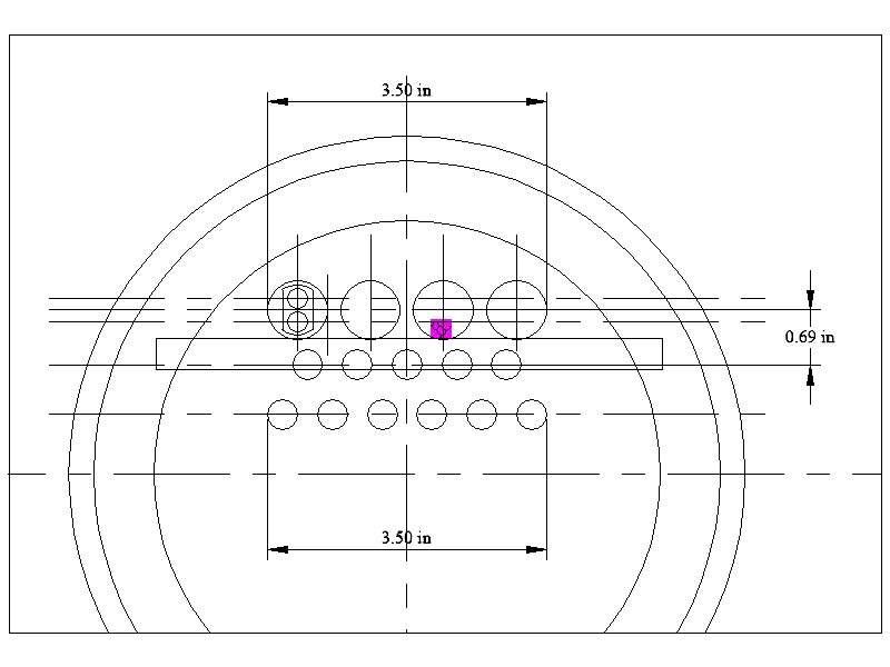
It is the tube-plate of my wagon’s boiler, surrounded by the smoke-box nearly two inches larger in diameter. I have to solve forming the superheater elements and headers without obstructing any of the tubes and the sizeable petticoat-pipe. The latter, not yet drawn and hard to draw, is very close to the tube-plate, with its “hem” about level with the tops of the flues. The two steam pipes will lie along the shell, under the lagging, and enter the drum through the ring between it and the boiler at about the 9 and 10 o’clock positions – also not yet drawn.
The horizontal rectangle is a trial header location I can move, delete or copy more easily than in Alibre.
There are of course more fire-tubes than that: forty-four total, I think! I need show only the top two rows for this purpose.
I will need develop the drawing further, including adding the side elevation and perhaps plan, but the print so far is to help me gather the remaining details for that, from the project so far.
The flues are very close to the top of the shell because even the lowest water-level is some two or three inches above that: Hindley’s patented boiler design is intended to cope with steep hills.
.
What the heck is that purple square…? It just happened, perhaps by me accidentally pressing one of TurboCAD‘s umpteen mysterious ‘SEKE’ (combination-key) commands.
I have no idea what the figure is for, it cannot be moved or deleted, even closing the programme does not clear it. Magnified, its internal squiggle is a squared-off letter ‘B’ on a ramp, outlined in little black squares – totally, weirdly meaningless!
…….
Martin –
TurboCAD and Alibre use ratios or just numbers for scales. They don’t ask for suffix letters. TurboCAD makes printing very difficult by strange procedures not necessarily giving you what you’ve asked them for.
….
 12 June 2024 at 08:28 #735541
 Michael GilliganParticipant@michaelgilligan61133
It astonishes me to see that after 71 posts, the collective wisdom of this forum has not yet found a clear answer to Nigel’s [apparently] simple question.
This may, or may not be ‘theGrail’
https://youtu.be/hw6HpwJA8s0?feature=shared
… I am about watch it and would suggest that a few others do the same.
Nigel needs, and deserves, an answer …
MichaelG.
.
12 June 2024 at 09:11 #735545SillyOldDuffer
Moderator@sillyolddufferI’m afraid Nigel has missed my point, which is about step-wise refinement! Whilst the problem of how to draw a General Arrangement is unsolved, I suggest there’s little value at this stage in Nigel doing a 2D drawing of the boiler’s tube plate. Why is it needed?
Nigel is also attempting different levels of design with two different CAD tools, neither of which is easy to drive. To my mind this mixture is a glorious recipe for frustration. Better, I suggest, to put the time in needed to learn one tool well and then evolve the design by step by step, avoiding adding detail until the foundations are solid.
Nigel’s Steam Wagon is a seriously difficult project, and anything that smooths his way is worth considering. That includes starting again using a different approach!
Dave
12 June 2024 at 09:22 #735547 Michael GilliganParticipant@michaelgilligan61133
Having just watched the video that I linked …
All seems reasonably well-described except that I noticed no reference to the margins that printers typically require [yes, I may have blinked].
Full-bleed printing is, of course, available on many printers; but often requires the use of ‘photo’ settings.
MichaelG.
12 June 2024 at 09:51 #735556Tomfilery
Participant@tomfileryNigel keeps saying “TurboCAD makes printing very difficult by strange procedures not necessarily giving you what you’ve asked them for” and despite many attempts by multiple people on this forum he can’t move on from that!
TurboCad printing options are not complicated, but there are traps for the unwary! As others have said, it is perfectly feasible to print large drawings on an A4 printer and the software will collate the sheets and print index marks on them to aid their subsequent alignment – it is all there out of the box.
Nigel uses a Viewport for printing. I have previously commented on his loose language in respect of this. You set a Viewport in the Model space and then apply a View to the paper space, which reflects the contents of the Viewport. You can set scaling factors on both the paper and the Viewport, which I suspect is part of Nigel’s problem. Use of a Viewport/View allows you to print a reduced size version of your drawing showing the original dimensions – though you can break that link if you actually want the scaled down sizes.
To avoid these traps, he could simply copy his drawing (or part thereof) and paste it into a Paper space, then apply whatever scaling he wants to make it fit the current paper. Alternatively, he could change the paper size to accommodate the drawing – you can clearly see where the drawing exceeds the size of the current paper. I don’t believe he has actually answered the question (raised months ago) as to whether his printer actually prints from any application! That might be a good pace to start.
Nigel is clearly working in a vacuum, without a good grasp of what he’s actually doing. I further suspect he is someone who expects his software to work how he would like it to, rather than how it actually does! I fear, as SOD says above, that his dalliance with Alibre will only result in further frustration when he refuses to take on board the suggestions of others – namely Jason B and Peter Jupp. Nigel would benefit from reading carefully the posts on this topic (rather than skimming them as I suspect he does).
I just can’t see Nigel moving on from where he is at the moment. I have persisted with TurboCad and am producing 3D drawings regularly (with TC 16 – so not the best for 3D), so it can be done. You have to get your head around how the software wants you to draw your objects and how to place them for joining to others.
Tom
-
AuthorPosts
- Please log in to reply to this topic. Registering is free and easy using the links on the menu at the top of this page.
Latest Replies
Home › Forums › CAD – Technical drawing & design › Topics
-
- Topic
- Voices
- Posts
- Last Post
-
-
Colchester Chipmaster Clutch question
Started by:
Peter_H in: Manual machine tools
- 4
- 7
-
6 July 2025 at 10:47
Peter_H
-
Pragotron Slave Clock
Started by:
renardiere7 in: Clocks and Scientific Instruments
- 3
- 3
-
6 July 2025 at 10:45
 Robert Atkinson 2
-
Starrett and other tool manufacturer wood boxes
Started by:
Ian Owen NZ in: Workshop Tools and Tooling
- 8
- 11
-
6 July 2025 at 10:24
SillyOldDuffer
-
Sanjay’s Banjo Engine
Started by:
 JasonB
in: Stationary engines
- 3
- 7
-
6 July 2025 at 09:58
 JasonB
-
In memoriam: Peter Neal
Started by:
jamesn in: The Tea Room
- 1
- 1
-
6 July 2025 at 09:53
jamesn
-
Wickseed power hacksaw 8” information
Started by:
simonkeeligan@me.com in: Beginners questions
- 2
- 2
-
6 July 2025 at 07:44
 Nicholas Farr
-
M type top slide conversion??
Started by:
jimmyjaffa in: Beginners questions
- 7
- 13
-
6 July 2025 at 06:55
 JasonB
-
Bentley BR2 Rotary Aero Engine
Started by:
notlobgp14 in: Miscellaneous models
- 4
- 8
-
5 July 2025 at 22:46
notlobgp14
-
New member
Started by:
nige1 in: Introduce Yourself – New members start here!
- 3
- 6
-
5 July 2025 at 22:41
notlobgp14
-
Starrett micrometer.
Started by:
Graeme Seed in: Workshop Tools and Tooling
- 7
- 14
-
5 July 2025 at 21:30
 peak4
peak4
-
Twin Engineering’s heavy mill/drill quill removal
Started by:
Martin of Wick in: Manual machine tools
- 11
- 25
-
5 July 2025 at 21:10
Martin of Wick
-
Dial test indicator vs Dial indicator
Started by:
martian in: Workshop Tools and Tooling
- 17
- 25
-
5 July 2025 at 20:19
martian
-
Speed camera
1
2
3
Started by:
 David George 1
in: The Tea Room
- 23
- 60
-
5 July 2025 at 19:40
John Haine
-
Any ideas how to repair this?
Started by:
Ian Parkin in: Related Hobbies including Vehicle Restoration
- 11
- 14
-
5 July 2025 at 15:36
Pete Rimmer
-
Chucking Money Away!
Started by:
Chris Crew in: The Tea Room
- 6
- 8
-
5 July 2025 at 12:55
Chris Crew
-
2 Machine lights
Started by:
modeng2000 in: Workshop Tools and Tooling
- 2
- 8
-
5 July 2025 at 11:58
Dalboy
-
Boxford lathe & vertical mill VFD conversion help with start stop
Started by:
Andrew Schofield in: Beginners questions
- 8
- 10
-
5 July 2025 at 11:39
Clive Brown 1
-
1965 Colchester Chipmaster
Started by:
andyplant in: Introduce Yourself – New members start here!
- 6
- 10
-
5 July 2025 at 11:09
Rod Renshaw
-
What Did You Do Today 2025
1
2
…
6
7
Started by:
 JasonB
in: The Tea Room
- 33
- 175
-
5 July 2025 at 09:26
Nick Wheeler
-
Amadeal AMABL210E Review – Any Requests?
1
2
Started by:
 JasonB
in: Model Engineer & Workshop
- 16
- 39
-
5 July 2025 at 05:49
Diogenes
-
ML10 backgear
Started by:
alexander1 in: Manual machine tools
- 3
- 5
-
5 July 2025 at 00:11
 Bazyle
-
The Perpetual Demise of the Model engineer
Started by:
Luker in: Model engineering club news
- 13
- 25
-
4 July 2025 at 17:06
 JasonB
-
Advice moving 3x machines
Started by:
choochoo_baloo in: Workshop Techniques
- 5
- 5
-
4 July 2025 at 15:46
 Bazyle
-
Black plastic to replicate Bakelite
Started by:
Craig Brown in: Materials
- 8
- 9
-
4 July 2025 at 15:35
 nj111
nj111
-
Firth Valve Gear
Started by:
Andy Stopford in: Traction engines
- 10
- 22
-
4 July 2025 at 14:42
duncan webster 1
-
Colchester Chipmaster Clutch question
-


