TurboCAD Query: Maintaining Rendering Acrss File-types?
TurboCAD Query: Maintaining Rendering Acrss File-types?
Home › Forums › CAD – Technical drawing & design › TurboCAD Query: Maintaining Rendering Acrss File-types?
- This topic has 112 replies, 18 voices, and was last updated 18 April 2023 at 17:47 by
Andy_C.
-
AuthorPosts
-
6 April 2023 at 01:25 #640310
Nigel Graham 2
Participant@nigelgraham2Jason –
Long-winded because no direct tools!
The reference-manuals are hard to search. That for TC2019 works, but the pdf and document page-numbers for TC2021's manual hopelessly mismatch. However they reveal the truth. You need to know –
a) The object generation type: "solid" or "surface".
b) The model's assembly order (?).
and c) If your edition of TurboCAD has the tools!
Mine (TC 2021 Deluxe) doesn't. It cannot Fillet 3D objects. Nor Chamfer them. Both tools work only on 2D polygons, hence in 3D only the extensions of their own edges. They exist fully only in the more advanced, 'Platinum' editions.
…………
David –
TurboCAD itself does not mention ACIS. The word is in the manuals but these cover several versions of each number-type of TurboCAD.
My experience is the opposite! I followed Part One of the MEW Alibre series, and even modified the foot of that scribing-block for better stability. Then that was it. I missed the next two instalments so lost the lot.
The SE (C) web-site holds an exercise modelling a cast or welded bracket, including fillets. Then that was it. I could not find its next exercise and hit a solid wall.
Alibre and later, SE, showed just how much I'd need learn from scratch. I realised designing even, say, a simple engine part 3D-first would be hard enough; I could never reach designing the whole engine in 3D. I deleted them and their exercises.
Alibre and SolidEdge look similar, and differ considerably in appearance and approach from TurboCAD. TC is just as hard but does not insist on 3D 'Models' though certainly lets experts work from 3D. You can create orthographic drawings straight off..
The 3D drawing that prompted my question is of a simple wire-reel made from 4 pieces.
……
You are right about quality. as well as precision, TurboCAD's Users' Forum gallery is full of beautiful, near-photographic engineering and architectural pictures. Some are by professional TC users but others by amateurs.
Most of those 3D-models are purely art-works; but one was by a model-engineer in New Zealand, of the miniature, triple-expansion marine engine he was building.
.
Yes, TurboCAD works for me, to a point. There are important areas I cannot grasp properly. Nor can I create 3D drawings of any worth.
3D models are valuable to very skilled CAD users; shown on this Forum and in the magazines. My very simple, rough accessory sketches are no good for originating functional elevation drawings or as assembly and GA drawings.
6 April 2023 at 09:13 #640323lee webster
Participant@leewebster72680Hi Nigel,
I dont know about others who have commented, but I would like to see a picture of what you are doing posted here. Screenshots or images from TurboCAD are a rare sight!
6 April 2023 at 09:44 #640327Nigel Graham 2
Participant@nigelgraham2OK: ones I have on my album.
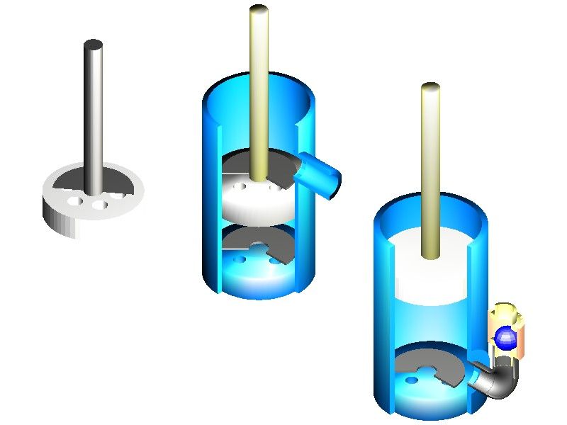
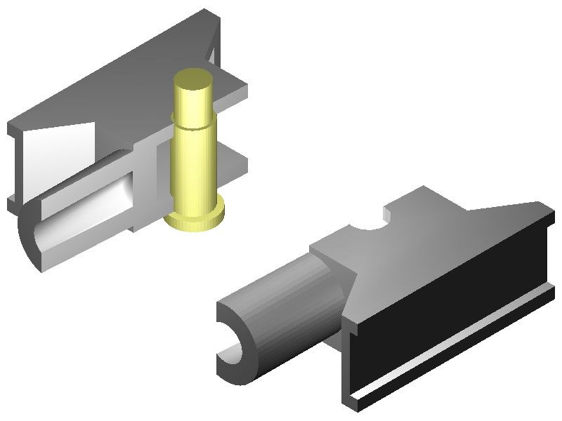
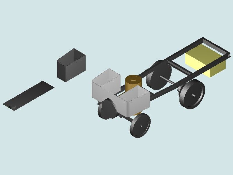
The sectioned pumps were to help discussing types for a particular application. The rest are really only exercises, of not much practical use: Respectively, the lift and force pump to show their principles; one of my steam-wagon cross-heads (made from a pair of castings I think originally for a 7-1/4" g. loco), and an attempt to model the wagon itself as it is so far.
I soon realised the lorry is far beyond me – the wheels for example are of two rose-pierced discs, not solid. The two bit as floating in the background are a "spare" footplate/ bunker floor and a bunker, where I generated them. Making the bunker look like a bunker with a floor was one of the hardest parts of the exercise. It was either a solid block or a wall with no floor to stop the coal falling on the ground. I soon realised this exercise is right at my limit, lacking any details like boiler fittings, steering-gear and springs, though I think I later added the two crew seats and a simple block representing the vertical engine between them.. They are just rectangular blocks though.
6 April 2023 at 10:40 #640342SillyOldDuffer
Moderator@sillyolddufferPosted by Nigel Graham 2 on 06/04/2023 01:25:37:
…
Alibre and later, SE, showed just how much I'd need learn from scratch. I realised designing even, say, a simple engine part 3D-first would be hard enough; I could never reach designing the whole engine in 3D. I deleted them and their exercises.
…
And that was a massive mistake! The endeavour came to a dead-end and all the effort put into Alibre was wasted. Worse, a partial understanding of Alibre is added to the muddled understanding of all the other software Nigel has abandoned. Switching prematurely between products is confusing.
There is no easy answer. My advice to Nigel is to:
- Choose a software package that other people on the forum are familiar with so they can help. The problem with TurboCAD is that only Andy knows it, and it appears TC's way-of-working and terminology are different to other packages. Alibre, FreeCAD, Fusion360 and Solid Edge probably have the most users.
- Find one with a recent 'get you started' tutorial. The MEW Alibre series is suitable, but it has to be followed. "I missed the next two instalments so lost the lot." is an unacceptable confession – a serious learner would have put that right. A disciplined approach is essential.
- Manage expectations ruthlessly: all CAD requires the user to familiarise himself with their workflow and command set. And do not expect to start by drawing a whole engine! It's necessary to learn how to model simple single parts, gradually building up to complex shapes. There are no shortcuts – the user has to put the effort in – hundreds of hours. Persistence.
- Clear mind of previous beliefs and convictions. For example, modelling in 3D CAD is a different mental process to drawing in 2D. No good fighting it – the user has to adapt because software can't.
- Give poor old brain a chance! Takes more repetition and effort for me to learn anything new nowadays, and I find learning hard-work. Impatience is fatal to learning CAD, or anything complicated. Strike a balance between work and rest. Worst approach by far is to binge CAD for hours on end and then leave it for a month. Little and often works best for me, big gaps allow time to forget.
- No excuses: CAD products may have quirks and bugs galore, but they do work. Millions of people have mastered them. I've got into fights with FreeCAD, Fusion360 and Solid Edge. The most common problem turns out to be me not driving them properly – using the wrong commands to get a result, or as Eric Morecambe put it "I'm playing all the right notes—but not necessarily in the right order." When CAD goes wrong, only the human operator is smart enough to fix it!
Professionals often avoid painful time-wasting teething trouble by going on a course, perhaps 5 days of explanation and hands-on exercises to nail down the basics firmly. Only after the basics are grasped do reference manuals start to make sense. It's possible to DIY, but allow plenty of time and keep an open mind. When it's not going well, chances are something simple was mis-set earlier. Backtrack, and think again. Don't assume that the first thing that worked is the right answer!
Self-teaching is hard work, because teacher and pupil are both confused. And exploration and analysis are harder than learning.
If all else fails, buy a drawing board. I make lots of small simple parts, and most of the drawings are done on paper, often back of an envelope!
Dave
6 April 2023 at 10:54 #640345 Ady1Participant@ady1
Some of them are for artists more than engineering type work but the stuff they can produce and their flexibility makes you wish they were for engineers
6 April 2023 at 10:57 #640346Andy Ash
Participant@andyash249026 April 2023 at 11:10 #640351 Ady1Participant@ady16 April 2023 at 11:22 #640353
 JasonBModerator@jasonb
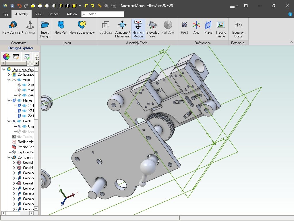
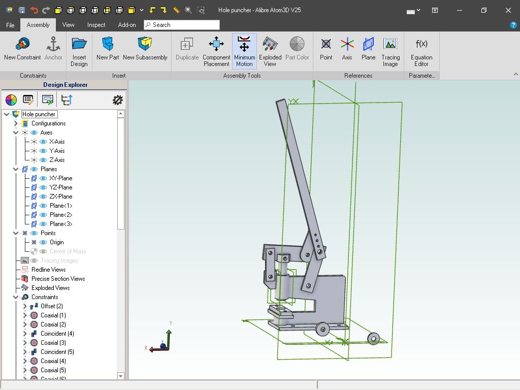
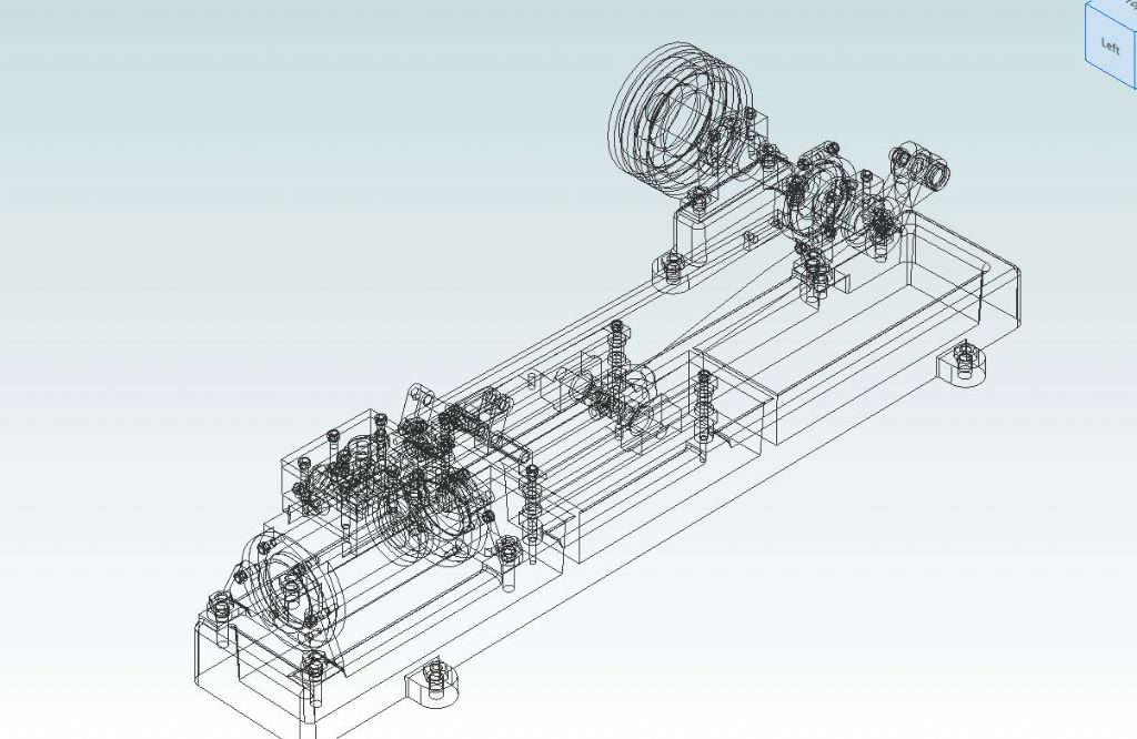
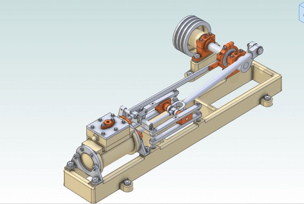
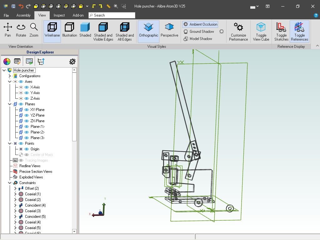
If Nigel can only get wireframe then no wonder it is difficult. Alibre has the option to show items in wireframe but it is something I never use as it becomes just a jumble of lines once you get to anything of any detail and it does not even differentiate hidden or visible, take this example, it's a Stuart Victoria but you would be hard pushed to tell what it is or make out individual parts
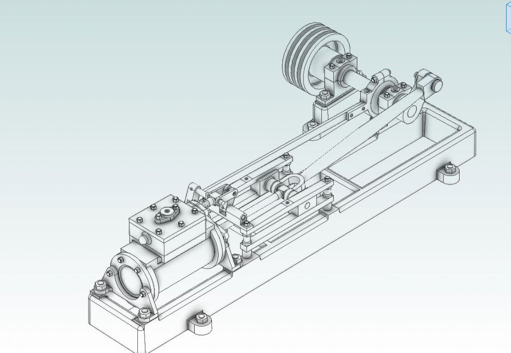
Using "illustration" does at least hide the hidden lines if you want a basic B&W image
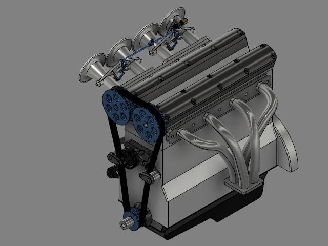
There are a couple of other options but the one I tend to use is "shaded with visible edges" Immediately you can see where one part starts and another ends, I use colour to distinguish materials which also helps see what is what.
6 April 2023 at 11:49 #640355Nick Wheeler
Participant@nickwheelerPosted by SillyOldDuffer on 06/04/2023 10:40:54:
Self-teaching is hard work, because teacher and pupil are both confused. And exploration and analysis are harder than learning.
They're not confused but ignorant. And that leads to the self-perpetuating frustration repeated here.
I've mentioned this several times, but Nigel needs some one-to-one teaching to fill in the gaps in his understanding and reset his faulty thinking.
6 April 2023 at 11:57 #640357 Ady1Participant@ady1Posted by JasonB on 06/04/2023 11:22:10:
If Nigel can only get wireframe then no wonder it is difficult.
Using "illustration" does at least hide the hidden lines if you want a basic B&W image
The view option is quite important so Turbocad must have the same sort of thing
If you look at my toolbar the entire top section gives viewing options
6 April 2023 at 12:33 #640361Andy Ash
Participant@andyash24902In TurboCAD, even the free versions have the capacity to render. I suspect it is more capable than the CAD examples shown by Jason.
With TurboCAD you can create textures from bitmaps or with geometric designs. These can then be rendered onto facets. Typically this approach is optimised for accelerated video hardware which will have dedicated texture memory in the rendering pipeline.
This is more than is required for CAD work, but it stems from the early days of 3D graphics where ACIS originated. API's like OpenGL and so on are optimised to deal with shaded triangles, which support virtual environments like flight simulators and video games. TurboCAD also has a range of built in materials which can be attributed to entities and facets to get a quick and dirty rendered output.
In principle TurboCAD is ray traced with flexible lighting and there are several different levels of rendering. Its a whole pile of hassle to set up lighting and for me even to faff around with textures.
The only thing that I'm interested in with 3D is dimensional accuracy. 3D CAD helps me to calculate and define 3D things that I would struggle with otherwise. It is important to me that I can accurately describe the shape of solids. Wireframe is my main render scheme, to do geometric construction and alignment. I rarely need to sell or promote anything, just to get stuff made.
It's much more important to me that I can accurately pick a vertex from the wireframe fuzz, select an associated facet and start manipulating the model on that facet. If I know how to do that with TurboCAD, then there is no limitation about what it can do for me.
6 April 2023 at 13:12 #640366blowlamp
Participant@blowlampPosted by Ady1 on 06/04/2023 10:54:23:Some of them are for artists more than engineering type work but the stuff they can produce and their flexibility makes you wish they were for engineers
Hi Ady1.
The links you have posted about MoI do make it look like an application that might be used mainly by artists, but as a user of MoI, I can say that it is more than capable of accurately modeling anything I've seen here. I use it to produce 2d & 3d engineering output, with or without dimensions and it's mathematical precision is just like that of AutoCad etc. So it's not to be confused with something like Sketchup.
MoI doesn't do 'assemblies', but it is very good for making any sort of mechanical part, quickly and quite easily, with a little practice.
Martin.
6 April 2023 at 13:48 #640373SillyOldDuffer
Moderator@sillyolddufferLooking at Nigel's examples, they're all advanced work, not easy for a beginner! Trying to run before one can walk is a common mistake – look at my bruises!

In the above, I see, from left to right:
- A 3 part assembly, consisting of:
- A piston part with six holes drilled for water, and one central hole for the rod
- A flap valve part, sectioned at 180°
- A piston-rod part, joined to the piston part
- A 3 part assembly, plus 1 assembly (the piston above):
- A cylinder part, with angled exit pipe, both sectioned
- A cylinder base-part, with 4 holes drilled for water
- A flap-valve part, sectioned at 120°
- The pump piston, flap valve and piston rod assembly
- Similar:
- A different cylinder part with exit flange at bottom (sectioned)
- A pipe elbow part, joined to the cylinder exit (sectioned)
- A ball-valve housing part, joined to the elbow (and sectioned)
- A ball part, not sectioned, assembled inside the ball-valve housing
The drawing is of 15 models (eleven parts and four assemblies), each with challenges, and polished with colour and sectioning. It's an extremely hard target for a beginner who can't get chamfer to work yet!
I wonder if Nigel is beating himself up by aiming too high at the outset? The examples aren't difficult once the basics of modelling are understood, but they're beastly hard if you don't.
Dave
,
6 April 2023 at 14:15 #640374Nick Wheeler
Participant@nickwheelerI'd suggest that somebody who knows what he's doing – and how to explain it – could use those pumps to help Nigel pull himself out of the hole he's dug for himself in a couple of hours. That would involve suggestions on which profile to extrude/cut/revolve the initial solid from, use of additional planes/geometry, why constraints are important, using existing parts to create new ones directly in place, joining the parts to create an assembly and proving it moves as intended, and how to produce the drawings Nigel considers to be so vital.
6 April 2023 at 16:04 #640381 Ady1Participant@ady1
That's all I do
Make each little part in its own little file, easy peasy 90% of the time
When you've done the parts you need, dump the lot into the assembly program section and cobble them together
edit: and I don't get hung up on threads etc, I just join the holes together with the coaxial constraint command, I want to see it working before I get down to any assembly nit-picking details, I've only ever done about 4 threads and 2 bolt heads in 3 months, all the stuff I've put up in here is held together with its holes aligned and it works fine
Edited By Ady1 on 06/04/2023 16:13:29
6 April 2023 at 20:26 #640425lee webster
Participant@leewebster72680I did watch some youtube vids about TurboCAD. I couldn't see myself working in what I thought was the the only drawing option, wireframe, so I deleted the programme. Credit to anyone who can!
Have you sorted your problem now Nigel?
I will ask another question, just out of interest, It's a bit off topic. Are all the parts separate bodies (piston, cylinder etc) or all drawn in the same body? The reason I ask is that drawing all the parts in the same body was a mistake I made when first starting with Sketchup. Learning the basics of Sketchup helped me understand other cad programmes.
Edited spelling mistake!
Edited By lee webster on 06/04/2023 20:48:59
6 April 2023 at 20:45 #640428Nick Wheeler
Participant@nickwheelerPosted by lee webster on 06/04/2023 20:26:41:I will ask another question, just out of interest, It's a bit off topic. Are all the parts seperate bodies (piston, cylinder etc) or all drawn in the same body? The reason I ask is that drawing all the parts in the same body was a mistake I made when first starting with Sketchup. Learning the basics of Sketchup helped me understand other cad programmes.I use Fusion360, and make all the parts of a 'thing' as components – bodies are very different things – in the same file, so this
is saved as one thing even though it contains most of the parts necessary to build a working engine. It means each part can be built where it's going to be used, using the actual geometry that it fits which saves a great deal of extra design work. To me, saving each piston/rod/camshaft/throttle spindle/etc as a separate file would be like saving a novella as separate paragraphs.
6 April 2023 at 20:52 #640429lee webster
Participant@leewebster72680I use the same process in Designspark Nick, but I was wondering about Nigel's TurboCAD files. I don't know anything about the design process in TC.
7 April 2023 at 01:13 #640447Andy Ash
Participant@andyash24902I obviously can't say what Nigel does, but in TC there are loads of options for componentisation. If you want, you can create all the components in different files. I don't do that, but occasionally the scope of what I'm doing will change, or maybe I'll steal something from a previous design and use it in a new one. In this sense TC supports cut and paste.
You can cut anything from one document and paste it into another. You will have issues if you cut and paste between metric and imperial drawings, but you can convert the units at the source or destination before the transfer and then there are no problems.
My version of TC happily deals with step models which is quite useful for me because I do a lot with electronic components and most will have a step model of some kind. Also it will deal with dxf and dwg files so models for sheet metal fasteners are usually available online.
Within TC itself, there is an idea of promotion of entities. Lines and arcs combined promote into polylines. Closed polylines on a plane become surfaces. Surfaces can be extruded into solids. Solids can be interfered with one another into ACIS solids.
You can create other kinds of solids outright. Obviously there are spheres,cylinders and boxes, but you can also do donuts prisms and cones. There are also different extrude schemes like simple extrude, rail extrude (using a 3d polyline), spin. Also available is lofting which will interpolate a solid between two different facets.
There are a few "novel" construction tools, but the most useful is the "gear contour". If you want to make straight or helical gears, either DP or Module, you can just fill out a form and it will give you the correct gear outline which you can extrude into a straight cut gear, or twisted extrude into helical or herringbone.
When you promote objects as described previously, it is different from grouping them. Behaviourally it is similar but a group is just a group. You can do new things when you promote objects, but a group just preserves and protects positional relationship between any grouped entities.
TC has two modes of operation 2D and 3D, each has it's own selector. the 2D selector is a reference point and a rotation handle. The 3D selector is a reference point and three rotation handles, one in each axis. The 2D selector is constrained to the current workplane, but the 3D selector works anywhere in 3D space. The 2D workplane can be moved anywhere within the drawing but usually you set it either to a facet of some object or the "world" orientation. If you want you can define a random plane with three points. There are other schemes for setting the workplane.
Beyond groups, there are blocks, symbols and then parts.
Blocks work within a drawing. You might have multiple instances of a screw. The drawing contains a block which is a kind of subdrawing, and can be placed multiple times in the main drawing. If you edit the block then all instances in the drawing change. Then there are external references. These allow you to place another drawing (document) into the present one in the form of a block. External references are somewhere between blocks and symbols, but both are manipulated through the block palette.
Then there are symbols. Symbols are drawings one file per symbol which you can use in any new drawing. These symbols are just drawing files, but they are called up with the library palette. Not that I have tested it, but think an external reference will update immediately the external reference changes. I think a symbol is different because the entire content of the symbol is inserted into the drawing as a group. You can explode a symbol in the drawing and change it, but I don't think you can do that with a block.
Finally, there are parametric parts. TC supports the Ruby programming language. You can create symbols which have parameters. You could describe a cheese head screw with variable length. You write a program which defines how to draw the screw. When you place the part, it asks how long the screw should be, and that becomes the screw you wanted. Don't ask me how to do this! I think I probably could, but it would take me a while to figure it out.
Ruby is not a programming language I have used. I can't remember what exactly I was doing but I did do something programmatic a while back. For me it was simpler to write a program that outputs a dxf file. I wrote than in C which is the language I use most. It's not actually as hard as is sounds for simplistic needs. I think I might have been laying out logarithmic graduations – like for a slide rule. DXF is a simple text format so it was easiest to generate the lines as a DXF file and import it to TC.
Edited By Andy Ash on 07/04/2023 01:30:23
7 April 2023 at 11:32 #640480lee webster
Participant@leewebster72680Thanks Andy.
I can't say that makes any sense to me! I am so used to the quick and easy design process in Designspark, that trying something different isn't easy. Designspark lacks a lot of features, but it mostly does what I want to do.
7 April 2023 at 13:08 #640487SillyOldDuffer
Moderator@sillyolddufferPosted by lee webster on 07/04/2023 11:32:10:Thanks Andy.
I can't say that makes any sense to me! …
I found it enlightening though.
One way of comparing cars is to drive them, but this only works because vehicles have a standard control interface. (Admittedly small differences like right or left hand-drive, automatic and manual transmission, and how to turn on the lights cause consternation!)
However, when driving a car, it's often useful to have an understanding of what's under the bonnet. My father-in-law needed a new clutch every 20,000 miles because he didn't understand how they worked and couldn't comprehend that his driving style wrecked them. Nothing wrong with his driving, he assured me!
CAD is nowhere near as standard as driving a car. There are wide variations. Newcomers are faced with a huge number of buttons that either appear and disappear or stop working depending on context, different terminology, different workflows, and multiple ways of achieving the same end, some of which limit what can be done later.
CAD software that's easy to learn is inevitably too simple for complex work, whilst CAD that supports complex jobs, isn't easy to learn.
Having read Andy's description I now understand why TurboCAD seems so alien to me. It's because their approach differs from what I'm used to! FreeCAD, Fusion360, and Solid Edge have much more in common with each other, and I think I see the same basics in Alibre and Solid Works. May be a mistake trying to explain TurboCAD to Nigel, because the gap between what he has and what I know is too big.

Dave
11 April 2023 at 20:17 #640934Nigel Graham 2
Participant@nigelgraham2Having looked through the varied replies and picking a few points made….
.
My original question was about exporting drawings intact from TurboCAD. That's now sorted: I discovered how to save them as images directly, by TurboCAD's own file menu.
.
Regarding tuition, that needs a tutor or recourse to very expensive trade courses run for the companies for which CAD is primarily intended. So that's out for me.
'
Yes, different "makes" of CAD can differ considerably, but the CAD publishers themselves imagine their customers already know the principles common across most CAD packages; so need know only the specific controls.
It's worse when the designers invent jargon without explanations or etymology. With what is "Synchronous Mode", synchronised, if anything? In what order are drawings "Ordered"? Siemens gave me the impression of words owing their all to how SolidEdge works, and nothing to their real meanings. This obfuscation is one reason I abandoned SE as a potential TurboCAD replacement = another being Siemens' garden-path approach generally.
'
I abandoned Alibre not simply for missing two issues of MEW.
It was a mistake to learn from scratch totally new software I would soon have to buy; whereas I had made some progress with the TurboCAD I had purchased fully and I think more cheaply. Two or three years later, I tried again with SolidEdge (Community) but soon hit problems I could not overcome. When I realised how much I would have to absorb even to match my weak level of TurboCAD, my brain's survival instinct automatically dismissed SolidEdge as Impossible.
I've probably reached my maximum level for TurboCAD, enough to make fairly useable orthogonal drawings and rare, very rough, very simple 3D sketches. I accept irregular, infrequent attempts are not a good way to learn but that's what happens when each attempt ends in failure!
I don't know what "componentisation" is – apart from an assault on the language – but Andy Ash's knowledge of TurboCAD is far beyond what I could reach. I recollect seeing the term "parametric" elsewhere but I don't know what it means and I doubt its value to me. If I want to draw several screws I just draw one and copy as needed. I wonder if he uses a different edition to mine, as I don't really recognise his descriptions of rotation handles and workplanes in 2D. To me the orthogonal workplane is just "World" , essentially the flat background, like on paper. You can't make a 2D object a workplane because all objects are on one plane. You can in 3D mode; usually to construct one object on one face of another by making that facet the workplane. Note the phrase 'you can'. I can't.
'
Those cut-away pumps seem to have attracted some interest, even a compliment, very rough sketches though they are.
I knew they could never be Haynes Manual quality but were enough for their purpose. I had helped build the lift-pump on which I based a drawing to help discussing if that pattern would work in another application. (No, it wouldn't.)
I could draw them only because their parts are mainly simple cylinders, each set on a common axis. That made for easy assembling by co-ordinates from the part's original, arbitrary drawing positions. I do not know if Alibre and SE work like that. Something like a centrifugal pump would be impossible for me in any 3D CAD.
.
Drawing gears does not require drawing the teeth unless designing the teeth, which is unusual in model-engineering. Notwithstanding that large-scale CAD programmes offer gear-tooth routines, we normally need only the pitch and periphery circles. A text-note can quote the numerical details. That was normal on works drawings. Businesses did not pay draughtspeople to depict hundreds of teeth needlessly! Even if CAD just uses a bulk copying routine, it is one CAD aspect I need not worry about.
Similarly with screws, unless designing some very unusual thread, probably for power-transmission or material-moving; not a standard, static fastening.
.
TuboCAD offers Blocks to facilitate repeated parts or sub-assemblies. (In his CAD primer, DAG Brown uses tender wheels and their axle-boxes as an example.) However, they are extremely difficult to use and cannot be disassembled, e.g. to modify, without creating havoc. Best avoided: I copy the parts instead.
.
Someone said I can't draw chamfers. I can, but not fully, not in my TurboCAD version. The Reference Manual and tool menu are very clear on that.
'
I am well aware of the traps to avoid, such as trying to think in orthogonal manual draughting mode when using 3D CAD, and I do manage that.
Also, I do realise there is huge gulf between drawing in 2D or 3D a simple part like a plain disc flywheel, and drawing the whole engine. The difficulty is worst when assembling unsymmetrical parts with few, or no, common axes or vertices. It is far easier to draw the entire assembly orthographically.. TurboCAD lets you draw parts in place in a 3D model by its "Workplane by xxx" tools. I don't know if this is similar to as Nick and Lee suggest with Fusion and DesignSpark, but irrespective of software "make", this level is far beyond mine.
TurboCAD has a trap known to catch beginners. It tries to insist on 3D but allows you to draw orthographically instead; but you must decide at the start and stick to it. Changing mode in mid-work is horribly easy to do; and it creates havoc.
11 April 2023 at 21:33 #640945lee webster
Participant@leewebster72680Glad you got sorted Nigel.
I understand about staying with a piece of software you are used to. Like you, I don't get on too well with SolidEdge, but I wonder if I would feel differently if I had installed it a couple of years ago. I used it for a recent project designing a display stand for an oboe feather (not a feather from an oboe bird, but a peacock feather used to clean the inside of an oboe). I needed better text control than my cad programme offered. I have DesignSpark as my first port of call. Not as powerful as SE, but easy to use.
I wasn't very good at technical drawing in school, and some years after I left, I sold a lathe to a man I didn't know, but I recognised the name. My old TD teacher! When I told him my name he prodded me in the chest and said "I REMEMBER YOU!" Caps represent loudness here. He calmed down and bought the lathe anyway.
11 April 2023 at 22:22 #640955Andy Ash
Participant@andyash24902Hi Nigel. I would say that you have got a pretty good handle on how TC works. I wouldn't maximise my own abilities beyond saying that I've been using the thing for a long time, but not continuously. If you were to divide my knowledge amongst the years it has taken to gain – I don't think it would leave me looking very good.
The strange thing is that I read what you are writing and I can see exactly the same barriers I had in the descriptions of your own difficulties. I thought it was just me, but from what you are saying I think now it is probably the tool.The one thing you said that stood out was that switching from 2D to 3D mode sends everything haywire.
I remember that, really well. TurboCAD in the early 90's was actually two different software applications. 2D and 3D. You couldn't even move a drawing from one application to the other. You had to decide of you were going to do one or the other. If you changed your mind, you had to start again. The separate 3D software was virtually unusable in an era where the humble mouse was only just emerging for ordinary people. The mouse-wheel no-one had ever heard of!
I think the 3D software then was the basis for the whole package now, but it didn't have the 2D capability originally. Counter intuitively the 2D software didn't look any different back then as the current software does now. It has been steadfast. Although people were using the original 2D software I was one of those that didn't realise that the 2D behaviours were added to the 3D software. From memory the 3D software didn't get the 3D selector until the 2D behaviour was added to it.
It is really important to think that the modern TC software model space is just one thing. That world plane, is just one in the 3D space. You can put the plane anywhere you want. Any angle, any position, anywhere in the 3D space. Even if you only ever do 2D drawings, they are 2D in a 3D space. If you only know about 3D then someone can take your 2D drawing and leave you looking at a single line. Your drawing is still there, but you're just looking at the edge of your drawing.
There is an option that causes the workplane (WP) to be drawn in to your drawing as a red dashed line. It doesn't matter how you zoom or angle the WP, the red lines represent a square drawn on the surface of the current WP. It is important to realise that you can move both the WP and your view of the WP. If you look obliquely at the WP then the square is drawn obliquely. The red lines don't actually exist in your drawing. They're just drawn in like a laser light that you can just turn on or off.
Contd………
11 April 2023 at 22:23 #640956Andy Ash
Participant@andyash24902When you draw a 2D line, it goes onto the current WP. You can happily do a valid 2D drawing looking at the surface of the paper as if it were on top of an isometric cube. You ask to draw a square, but it looks like a rhombus until you view it from above like a 2D drawing. There can be multiple WPs in any drawing at any time. In principle there can be as many WPs as there are 2D entities. Although you can define specific (named) WPs there is no actual need to explicitly define them at all.
To qualify as a 2D drawing, the general TC3D drawing must contain no 3D entities. Moreover, there must only be one WP on which all those entities exist. In my mind at least, the angle at which you view the 2D drawing does not change the 2D/3D status. If there is more than one WP or a 3D entity, it can no longer be fully represented on a sheet of paper. A 2D drawing is a special case of the general 3D TurboCAD drawing.
TC tracks every 2D object drawn, it remembers which WP a 2D object is on. if you are just casually editing a drawing and there are two different 2D objects on different WP's then TC will switch the current WP automatically. When you add a new 2D object, it will go into the drawing on the WP of the object you last touched. Touched, means snapped to, moved or selected etc. If you don't have the red guide plane switched on, you have no way to know where the current WP is unless you keep track in your head.
There are issues with this. If you don't realise, it's like the world of TurboCAD has gone nuts. Nothing seems to be right any longer. This is worse than a TC bug, of which there are some. It feels like a major headache because snaps go to the wrong place. Lines jump in random directions. Haywire!
As you get used to it, you get a sense of when the software is going to switch planes. From time to time you realise that the WP red lines aren't switched on. Sometimes they vanish on their own. I don't know why. I think that's actually a bug. Gradually you find yourself able to know when the WP will and won't be working in your favour. It becomes easy even though the WP red lines aren't there. Sometimes now I even forget to switch them on, until I get into something more difficult.
When the WP is not where you want it, there are lots of different ways to control where it goes. You just need to remember that once you set the WP explicitly, you mustn't touch anything that might not be on your intended new WP. If you do, your explicit selection disappears. Once you draw one 2D entity onto a new WP it is easer because others will tend to go onto that WP on their own. You can almost think of the WP as a semi visible cursor for 2D entities in a 3D space.
Once you master the WP, the 3D selector will feel like a gift instead of a burden. I can see from what you said, you have an excellent understanding of the 2D selector. The 3D one is identical with one truly beautiful difference. Snaps on 2D objects only work on the same plane as that of the entity that owns the 2D selector handle. Snaps with the 3D selector handle work anywhere in 3D space. If you select snap to intersection and use the 3D selector, you can move a 2D object onto an intersection between two lines on another WP.
Apologies in retrospect for typos!

Edited By Andy Ash on 11/04/2023 22:42:37
-
AuthorPosts
- Please log in to reply to this topic. Registering is free and easy using the links on the menu at the top of this page.
Latest Replies
Home › Forums › CAD – Technical drawing & design › Topics
-
- Topic
- Voices
- Posts
- Last Post
-
-
Generator size for vfd controlled 3 phase 5.5 kw motor
Started by:
PutneyChap in: Electronics in the Workshop
- 7
- 8
-
31 March 2025 at 21:47
John Haine
-
Clarke CL500M longitudinal feed screw
1
2
Started by:
Stuart Cox 3 in: General Questions
- 13
- 48
-
31 March 2025 at 20:42
john halfpenny
-
DIY Pendulum Timer – GPS-Synced Beat Analyser
Started by:
Chris Raynerd 2 in: Clocks and Scientific Instruments
- 1
- 1
-
31 March 2025 at 20:40
Chris Raynerd 2
-
Hello from Kent
Started by:
michaeljf93 in: Introduce Yourself – New members start here!
- 1
- 1
-
31 March 2025 at 20:05
michaeljf93
-
More Lidl questions
1
2
3
Started by:
old mart in: Hints And Tips for model engineers
- 25
- 54
-
31 March 2025 at 19:45
 Robert Atkinson 2
-
Lubrication of headstock bearings on a Clarke CL500M
Started by:
Howard Lyne in: Manual machine tools
- 10
- 17
-
31 March 2025 at 19:37
old mart
-
Special BA bolts from Chronos
Started by:
old mart in: Materials
- 2
- 3
-
31 March 2025 at 19:32
old mart
-
Blue crystals. Probably not meth?
Started by:
pjbiker in: Beginners questions
- 7
- 9
-
31 March 2025 at 19:22
old mart
-
Forum Software?
Started by:
 Vic
in: The Tea Room
- 2
- 2
-
31 March 2025 at 17:25
 Colin Bishop
-
Model Turbines
1
2
…
23
24
Started by:
Turbine Guy in: Stationary engines
- 28
- 599
-
31 March 2025 at 14:47
Turbine Guy
-
HOBBYMAT MD65 – JAMMED
Started by:
David ANDREWS 2 in: Beginners questions
- 4
- 8
-
31 March 2025 at 13:36
 Bazyle
-
What Did You Do Today 2025
1
2
3
4
Started by:
 JasonB
in: The Tea Room
- 23
- 77
-
31 March 2025 at 13:25
Diogenes
-
Tangential tooling
Started by:
Keith Matheson in: Workshop Tools and Tooling
- 8
- 9
-
31 March 2025 at 13:21
John Haine
-
RequiredOutside Diameter to Cut 5/16 BSF Thread
1
2
3
Started by:
James Alford in: Beginners questions
- 24
- 63
-
31 March 2025 at 12:48
duncan webster 1
-
April issue ME&W
Started by:
edintheclouds in: Model Engineer & Workshop
- 4
- 6
-
31 March 2025 at 12:44
edintheclouds
-
Beginner with newly bought lathe – many questions
Started by:
ell81 in: Beginners questions
- 14
- 23
-
31 March 2025 at 09:01
 Nicholas Farr
-
Messaging
Started by:
Howard Lewis in: New Forum Software questions, comments and Test Threads
- 2
- 3
-
31 March 2025 at 08:32
Howard Lewis
-
Black dye for anodising?
Started by:
Andrew Tinsley in: Materials
- 4
- 5
-
30 March 2025 at 20:59
 Roderick Jenkins
-
ME suppliers
Started by:
sonic_m1etn in: General Questions
- 17
- 22
-
30 March 2025 at 12:14
noel shelley
-
Painting topic for stationary engines
Started by:
 Steve Huckins
in: Beginners questions
- 8
- 8
-
30 March 2025 at 08:23
Adrian R2
-
New member from Sheffield
Started by:
ma1colm in: Introduce Yourself – New members start here!
- 6
- 6
-
29 March 2025 at 23:34
Zan
-
Half Scale 1/4HP A J Weed Engine
Started by:
 JasonB
in: Stationary engines
- 4
- 9
-
29 March 2025 at 19:46
 JasonB
-
My week this week! My workshop videos
1
2
…
11
12
Started by:
Phil Whitley in: The Tea Room
- 14
- 285
-
29 March 2025 at 16:56
bricky
-
Hello world
Started by:
sonic_m1etn in: Introduce Yourself – New members start here!
- 6
- 8
-
29 March 2025 at 15:42
old fool
-
Diamond grinder wheels – thoughts?
Started by:
peterhod in: Workshop Tools and Tooling
- 10
- 14
-
29 March 2025 at 11:24
 Vic
Vic
-
Generator size for vfd controlled 3 phase 5.5 kw motor
-
Latest Issue
Newsletter Sign-up
Latest Replies
- Generator size for vfd controlled 3 phase 5.5 kw motor
- Clarke CL500M longitudinal feed screw
- DIY Pendulum Timer – GPS-Synced Beat Analyser
- Hello from Kent
- More Lidl questions
- Lubrication of headstock bearings on a Clarke CL500M
- Special BA bolts from Chronos
- Blue crystals. Probably not meth?
- Forum Software?
- Model Turbines


