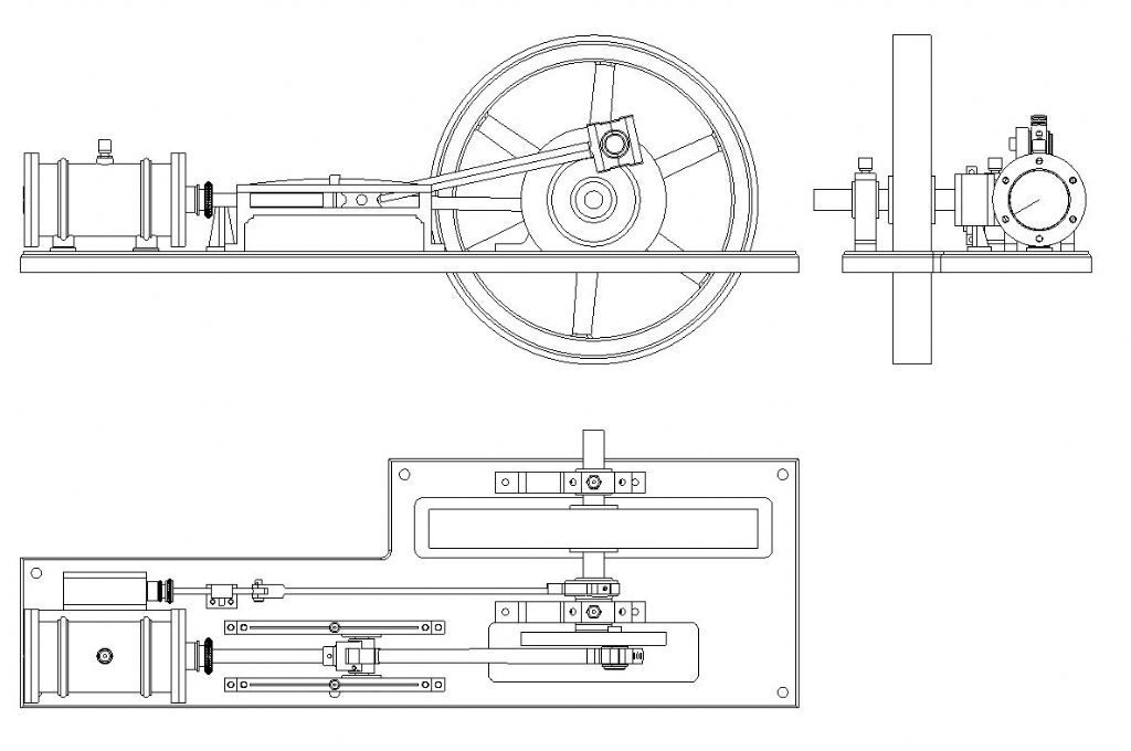
With thanks to all, it seems TurboCAD and I had been trying to do the right thing but were stymied by mistakes I had not known I'd made.
'
Dave –
Ah, it all makes sense now! My drawing was so faulty that it even stopped the programme from operating as it should.
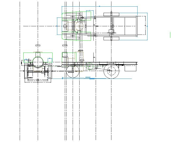
I have revised the Engine layout drawing, rooting out more hidden problems. Also, I divided the single-layer drawing into two layers for its two separate sets of components: one for the engine itself (just its major parts) and the other for the reference parts of the chassis.
This worked to the extent that I could at last copy and paste the main image to the Vehicle drawing.
TC dues use the word 'Explode', the tool-bar symbols rather confusingly making it seem to mean "Un-Group" , but it breaks polylines into single elements. In 3D it breaks solids into facets; and so do some other tools, unexpectedly, whether you want it or not.
'
John –
[Insert] – [External Reference] I'll have a look at that.
Just as well I'm not designing military vehicles!
'
Jason –
I'm not clear why you dislike orthographic drawings, necessary for the workshop. I tried Alibre and Fusion, but they both default to isometric-first. I do not know if you can switch them, but TurboCAD gives you the choice by default.
I'm afraid I don't understand your point about re-drawing.
Normally one divides a complicated assembly into General Arrangement, unit and component drawings, and tools like Layers facilitate this. If you draw, say, a lathe, then to modify the top-slide, you can replace the GA's top-slide layer with the new copied from the top-slide's own drawing. Whatever you do still means modifying the unit's own drawing.
Or do you mean design the whole machine on a single, very complicated, drawing but with each unit on its own layer so you can temporarily hide those you are not immediately working on? Then copy each layer into its own unit drawing?
The former is what I am trying to achieve! It seems from this thread that I was attempting the right approach but failed thanks to mistakes I had not realised, and which misled me into the wrong diagnoses and " cures" ..
However, I have no idea how this GA / unit / part system works in 3D – and you still need the 2D elevations for machining the parts.
'
I choose orthographic by default for two reasons:
'
Firstly-
Isometric drawings have always been important for explanations, assembly and servicing, but making things needs elevations, not pictures. I know it is common to put a small isometric rendering on an orthographic sheet to help you visualise the item, as e.g. Hemingway Kits use; but there is no reason not to draw the whole thing in 2D.
I gather you can take off the elevations and dimension them from an Alibre 3D model. You probably can in TurboCAD but I do not know how.
'
Secondly –
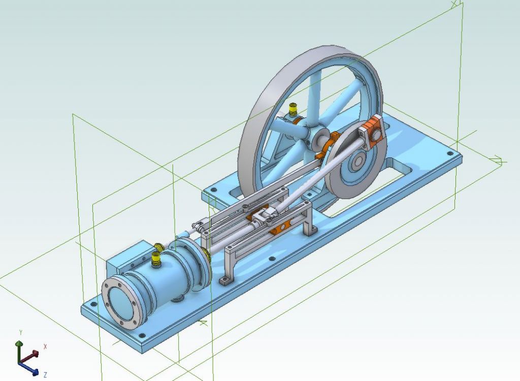
Frankly, I cannot learn 3D CAD to a useful level! An isometric version of my drawing above would be impossible for me, even with the same details still omitted.
I bought a CAD programme for this steam-lorry project (and others) after witnessing its possibilities at work, though they used SolidWorks. I knew it is a lot to learn but find orthographic CAD hard enough, 3D too hard.
TurboCAD was the only proper engineering quality CAD package available to amateurs at the time, at a sensible, up-front price; and was advertised in ME (and presumably MEW).. Not an open-ended "subscription" – and after sampling Alibre via the MEW offer, I realised no point in changing to another "make" having paid, and paid less than to Alibre, for TurboCAD with training materials, and made some progress in learning it.*
Luckily TC gives me that orthographic-only choice. (You have to be careful though not switch accidentally to 3D – that can create all manner of difficulties!)
'
* Looking at Paul (the CAD's) Tracy's web-site it seems TurboCAD offers an up-dated equivalent of the Deluxe 19 edition I use, and still at a sensible up-front price.
Nigel Graham 2.


