‘Tuning’ my steam engine

Advert

‘Tuning’ my steam engine

Home Forums Stationary engines ‘Tuning’ my steam engine

Viewing 11 posts - 1 through 11 (of 11 total)
  • Author
    Posts
  • #617584
    Iain Downs
    Participant
      @iaindowns78295

      Regular readers of the forum may be familiar with my thread on my interminable attempts to build a steam engine, to be found here.

      It ended on a high note with me reporting that the damnable thing actually RAN – on air mind you, but it ran.

      I wasn't particularly happy with how it ran though, it would not start on its own and could easily be stopped with a little drag on the flywheel. I left it alone for a while, though, whilst other things grabbed my attention (illness, retirement, house sales (in process) – dull stuff).

      Now retired (HOORAH!) I'm having a look at this again. I've gone and measured up what I've built and compared it to what I designed and then again, compared it to what I intended to design – and found, um, discrepancies.

      I throw myself on the mercy of the court.

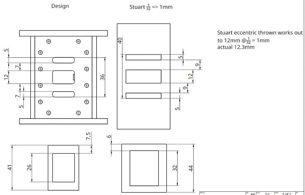
      So the basic port geometry was taken from a Stuart 5A. Specifically I scaled up so that 1/32nd inch = 1mm. No way was I translating to metric directly!

      Now I come to have completed the work, I see that the way I've drawn the ports doesn't directly map to the Stuart design. It's possible (though rather unlikely) that I had a reason for this and it wasn't just a mistake. If anyone could suggest a deliberate reason for the change I would happily pretend it was true and claim intent…!

      chest - design vs intended.jpg

      As you can see from the above, the port widths are a good match for the Stuart, but the separations are wrong.

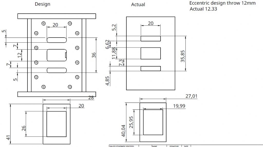
      To add insult to injury, The implementation of the drawings is a little out.

      chest design vs actual.jpg

      Clearly, that's entirely on me!

      Whilst I would be delighted if I could make this work by some simple trick, I think what I will need to do is something like this.

      1. Mill out the centre of the chest. The ports are around 5mm deep and the height from the top of the chest to the cylinder wall is around 12.5mm, so I should have plenty of 'meat'
      2. Carve out a block of cast iron to fit closely in the resulting space.
      3. Glue it in place.
      4. re-mill the ports according to the (new) design.
      5. smooth off the new surface (fly cutter probably)
      6. Make another D Valve.

      If there are alternatives (ideally featuring less work – and not involving remaking the eccentrics wink ) I would be most interested.

      For this I have two questions, I think. One. the glue. Whilst it's entirely possible that this will never run under steam, it may, so I would like to pick a glue which would stand steam. I also wasn't sure if I should pick a high viscosity one like JB weld or if something thinner was more appropriate. What would you recommend?

      Second question; Should I mill down to the level of the current base of the ports so the glue layer would be at the port level, or should I mill below the current port depth which would leave a layer of iron at the base of the new ports?

      Well that's the end of my dark confessions – any help as always will be appreciated.

      Iain

      Advert
      #3508
      Iain Downs
      Participant
        @iaindowns78295

        AKA – I done messed up…

        #617585
        Anonymous

          I wouldn't bother mucking about with the port spacing in the cylinder at this stage, although I would make them longer. I'd alter the slide valve width and cavity, and eccentric throw, to achieve sensible valve events. That way there are fewer parts to make and they are simpler parts.

          Andrew

          #617587
          JasonB
          Moderator
            @jasonb

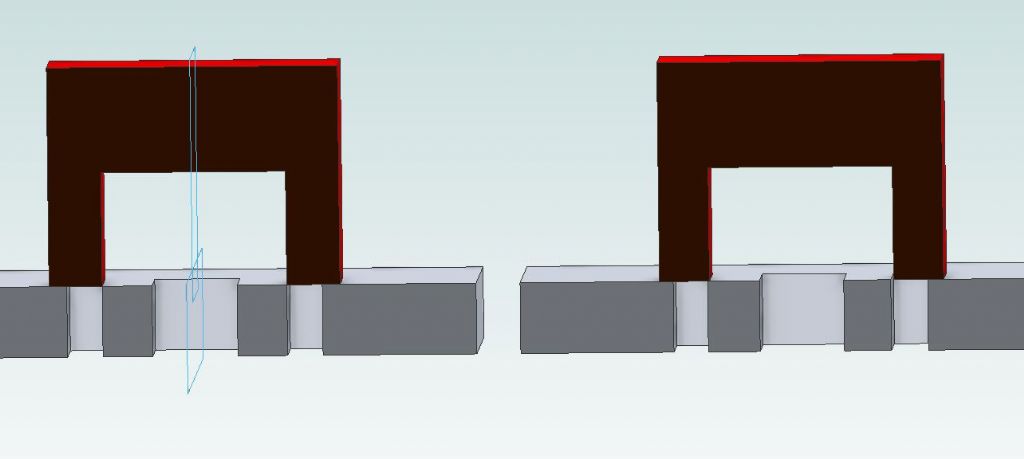
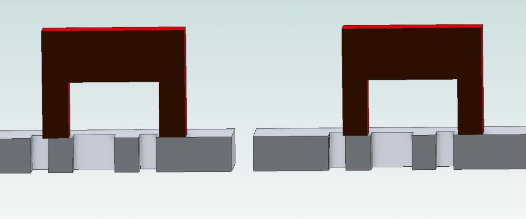
            I'm with Andrew, a slight reduction in the 25.95 of the valve might be useful but there is really not much that should affect running that much. What air pressure were you using as that will determine how easy it is to stop the flywheel. If anything your larger eccentric trow should allow it to breath a bit more.

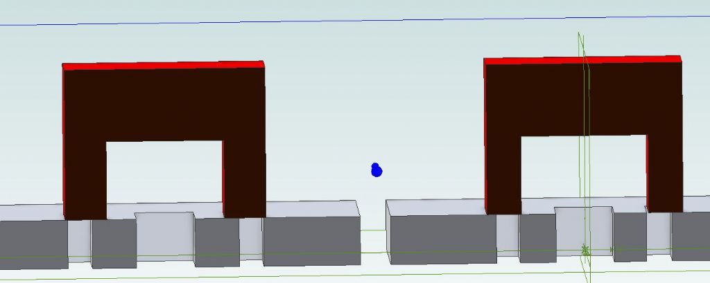
            Stuarts on left, your son right valves at mid point. Yours would actually need to be offset slightly but not critical

            id valve 1.jpg

            Now at full eccentric throw, again not a lot different.

            id valve 2.jpg

            #617595
            noel shelley
            Participant
              @noelshelley55608

              I'm with Andrew and Jason, Make the slide valve fit the cylinder ports and if need be change the eccentric to suit. Good Luck. Noel.

              #617598
              JasonB
              Moderator
                @jasonb

                Might even be the timing that is off as there really is not that much out with the ports/valve.

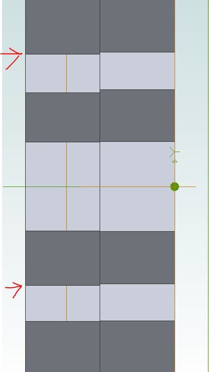
                If you really wanted to after looking at the easier to sort items then this shows the stuart again right and yours on the left. A bit of additional milling to the two arrowed edges would soon get things a bit more symmetrical and then just alter the valve to suit which could easily have a 2-3mm plate soldered to the face if it were milled back.

                id valve 4.jpg

                I see in the video your regulator valve seems to be set very low, OK for display but crank it up to say 50-60psi and then try stopping the flywheel. A single cylinder engine like this will probably only self start when the crank is in one of two positions and you will need to open the supply quickly to give it a kick to self start, just opening up the regulator you turning the know won't do it.


                Edited By JasonB on 17/10/2022 15:47:27

                #617610
                Iain Downs
                Participant
                  @iaindowns78295

                  Thanks for all your help as always…smiley

                  I wonder (Jason) if you are mixing up the design/ actual and design / Stuart?

                  The span of the ports (edge of one inlet to edge of the other is is 40 mm for the Stuart and only 36mm for my design.

                  It seems to me that the drawing above is for design vs actual where the actual is more or less right just a few tenths of a mm asymetrical.

                  I would be delighted (all) to rework the D valve to match the ports I've actually cut, but I must admit I have no idea what it would look like. Any advice on that would be most welcome.

                  I would also prefer not to rework the eccentrics. They are much more complicated beasts that the D valve or ports.

                  In terms of pressure, as you saw in the video I was running at about 20/30 psi. I was unable to get much above that – at least so I remember.

                  In that video the engine was running with the glands stuffed, but no piston rings so it may that there was a lor of leakage.

                  Jason – if you could check that you are looking at the right drawing, I'd be grateful. If anyone could suggest what the improved dimensions of the D-Valve would be I would be grateful.

                  Again, many thanks

                  Iain

                  #617624
                  JasonB
                  Moderator
                    @jasonb

                    Ah yes I had design vs actual.

                    However looking at my rather fuzzy copy of the 5A drawings I think you have your valve the 90deg out of position. It looks like the cavity is 1" x 3/4" 32 x 24 but the 1" is the horizontal dimension of the cavity as the 1" should match the 1" width of the slots in the port

                    Here it is with the correct 9mm between ports as Stuart design and with the valve set the other way round which if the 1 9/32" length is what I can read means there is very little lap so you will get steam into the cylinder much earlier.

                    id valve 5.jpg

                    #619463
                    Iain Downs
                    Participant
                      @iaindowns78295

                      Apologies for the gap in communication, but I have been enjoying the tender embrace of Covid for the last couple of weeks or so. Still slowly regaining energy but well past the worst.

                      I have good news and bad news on the engine.

                      Bad news: I am an idiot.

                      Good news: Jason is not.

                      In fact as I revisited the Stuart drawings after Jason's comment, I realised that I'd got my original comparison (at the top of this thread) entirely wrong. In fact, both the design for the chest and the D valve correspond exactly to what I expected from the Stuart. I appear to be unable to add 32nds together with any reliability.

                      And the actual D Valve is orientated correctly with respect to the drawing and not as I had done in my sketch above.

                      So there's nothing wrong with the chest and valve apart from the machining errors which amount to 0.1mm /.0.15 mm here and there.

                      Oh and the width of the slots is smaller than the Stuart, but I don't think that will have much of an effect.

                      I'm not sure if I will try and trim up the chest to be a little more accurate or just put the damned thing back together and see how it goes.

                      Thanks for making me check – clearly I was not expecting to have got it right the first time …

                      Iain

                      #619467
                      JasonB
                      Moderator
                        @jasonb

                        Iain, I just had a look back through your album for this engine and may have spotted something that could be hampering performance. Although shown on your drawings I could not see the clearance cuts on the cylinder cover spigot or the "bottom plates" spigot. Not having these cut into the spigots could be blocking the notch where the steam passage enters the cylinder bore and restricting the free flow of air.

                        #619476
                        Iain Downs
                        Participant
                          @iaindowns78295

                          Thanks for taking the time to have a look, Jason

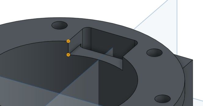
                          If you mean what I think you mean, there are no cuts on the covers or bottom plates. Instead the cut is in the cylinder wall.

                          steam inlet.jpg

                          As per the image above. I've just measured them and they are a bit uneven. They should be 5mm high (enough clearance for the piston rings on the piston) but are a bit less. One a about 4.2 and the other 3.8mm or so.

                          Ah!

                          Sorry. the penny just dropped. The inset in the cylinder cover will block the steam from the port above.

                          That's something I can fix and will. Many thanks

                          Iain

                        Viewing 11 posts - 1 through 11 (of 11 total)
                        • Please log in to reply to this topic. Registering is free and easy using the links on the menu at the top of this page.

                        Advert

                        Latest Replies

                        Home Forums Stationary engines Topics

                        Viewing 25 topics - 1 through 25 (of 25 total)
                        Viewing 25 topics - 1 through 25 (of 25 total)

                        View full reply list.

                        Advert

                        Newsletter Sign-up