Travelling Steady.

Advert

Travelling Steady.

Home Forums Model Engineers’ Workshop. Travelling Steady.

Viewing 13 posts - 51 through 63 (of 63 total)
  • Author
    Posts
  • #65471
    mgj
    Participant
      @mgj
      Sounds very reasoanble.
       
      I don’t know much/anything about drawing.
       
      All my experience in the steel line was hot rolling ferritic armour, and casting steel armour. Plus forging. What you might call the heavy stuff.
       
      Advert
      #65472
      KWIL
      Participant
        @kwil
        I have seen the same wave effect on Silver Steel bars, [which are ground to size]. If you have a reciprocating sleeve on such a bar the pattern shows up.
        #65483
        Terryd
        Participant
          @terryd72465
          Graham,
           
          I never said that your sample did not have an helix, I just drew your attention to the fact that you described drawn material as rolled. If your sample is cold rolled it may well have a helix. I merely said that I couldn’t see how drawn material has such a pattern and since than there have been more of the esoteric and outlandish ideas from a simple statement.
           
          The dies are fixed on a drawbench by the way and should not rotate, that can cause distortion and torsional stresses which would be disastrous to the strength of the steel. Cold drawn is straight due to the tension of the pulling process in much the same way that wire is straightened by a swift tug while one end is clamped. Silver steer is not left as drawn, it is centreless ground for dimensional and profile accuracy with the material passing a grinding wheel longitudinally which will explain the helix patterns seen.
           
          I wish folks would read what I write and not what they think I write.
           
          Best regards
           
          Terry
          #65640
          MICHAEL WILLIAMS
          Participant
            @michaelwilliams41215
            Graham Meek ,
             
            Q:
            Hi Michael,
            You say plain bar in your posting, is this straight from the rack as we say, that is un machined?
            Q-
             
            No – its plain bar in the sense of not yet having been machined . If ground bar or even a good piece of ordinary bar then use as is but if any bending or out of round or spiralling then preliminary operation of skimming betwwen centres or similar is needed .
             
            The point that I was making was that a sufficiently clean piece of plain bar or any pre machined item can be set up by dial gauge(s) by a simple method and there is no need for any of the bizzare complexities that some people choose to introduce .
             
            The condition required for precision work is that :
             
            (1) the work runs true at the chuck end .
            (2) the work runs true at the steady end .
            (3) the work axis coincides with the lathe axis .
             
            Put 1,2 and 3 together and it effectively means that if the work is running true anywhere and parallel to the lathe axis everywhere it is set exactly . Hence :
             
            Set bar best possible by eye with chuck jaws and steady jaws only just tight enough to hold . Set chuck end to run reasonably true by dial gauge . Traverse dial gauge along length of work in vertical and horizontal planes (that’s why two dial gauges are useful) and adjust steady to bring work parallel to lathe bed .
             
            Repeat a couple of times to get exact settings then tighten chuck jaws and lock steady jaws in place . Re test and make minute adjustments as nescessary .
             
            For work with tapered section pre calculate the correct run off of the dial gauges when work is parallel to lathe bed . Similarly for stepped work precalculate the offsets for each section .


            #65649
            MICHAEL WILLIAMS
            Participant
              @michaelwilliams41215
              Hi Graham M .
               
              First a minor apology – this site stopped working when I was doing final edit of last posting and a few words of politeness and some of the explanation seem to have been lost .
               
              Accuracy in any engineering task always comes down to being best compromise between what you aspire to achieve , what it is actually nescessary to achieve and what you can achieve in practice with available materials , equipment and skills .
               
              I’ve never seen a commercially available one but a travelling steady with all round support would have some merit for more delicate jobs – ie one made just like a hinged top fixed steady but travelling with the saddle .
               
              Bi .
               
              #65663
              mgj
              Participant
                @mgj
                I thought the whole idea of 2 fingers and a tool was to give the three ponts of contact and a triangle of forces with a resultant of zero. In other words there is no point is having an extra finger on a travelling steady – the tool povides the third finger and the force in the tool is counterbalanced equally and oppositely in the other 2 fingers. If you have an extra finger and it gets in the way of the tool, which it will, then you have to displace it which creates a twisting moment.
                 
                Lifewise a fixed steady – you still have 3 points of contact, (in almost all cases). One has a fixed finger because the steady is fixed (of course) so the tool is not in line ansd one still needs to generate that trianlge of forces.
                 
                Myford have not compromised – they have achieved perfection in suport as long as the width of the fingers in a TS spans the “width” of the leverage creating any turning moment (allows for the tool not being placed exactly centrally within the fingers) Won’t always, but should do when say screwcutting.
                 
                 
                #65666
                MICHAEL WILLIAMS
                Participant
                  @michaelwilliams41215
                  mgj :
                   
                  A Noddy level analysis of the forces acting in a travelling steady does indeed show that the system is determinate and stable . If , however , the analysis is done with proper understanding then a different picture emerges .
                   
                  The work piece is flexible and can bend both towards the tool and downwards even when a normal design travelling steady is in use . In a stable cutting situation nothing goes wrong but if any instability occurs , just like ordinary chatter , the work bounces around and you get at best variable depth cutting and at worst a dig in .
                   
                  Putting in the extra jaw for all round support would prevent movement in critical turning operations , especially with slender shafts , and what I said previously is correct .


                  #65675
                  mgj
                  Participant
                    @mgj
                    Well I think the business of workpiece bending had already been covered to a degree, as had the benefits in some cases of cylindrical supports – more of course on very slender shafts which are rather more specialised than the normal travelling steadies are designed or suitable for.
                     
                    As for your being right- yes I’m sure you are, – perhaps you had better let messrs Myford and Harrison know.
                     
                    Luv Noddy. – struggling to find a proper understanding. Some manners too.

                    Edited By mgj on 18/03/2011 13:55:23

                    #65681
                    mgj
                    Participant
                      @mgj
                      I don’t know Gray.
                       
                      If one is talking of finger wear, I’ve always adjusted the fingers. Line contact is theoretically best, but an arc is fine by both of us.
                       
                      Curved tips and rapid wear. Agreed, but I have usually just attacked the tips with a file – to “reface” them. but I stress I don’t use them so much these days. I have never used them enough to have to replace the tips/blocks
                       

                      Best solution – roller tips, if you can keep them small enough?

                       
                      Heating – hopefully overstated because I let my coolant pump pour coolant over the fingers because mine are always that close to the tool . Also lubricates.
                       
                      I think it depends on the job – the bog standard steady is going to be fine 99% of the time, and thats what the pros design them for – general purpose “slender shafts” if there is such a thing,
                       
                      The problem I find is one of size when dealing with very slender shafts. Because then the shaft IS going to flex like hell, and the fingers are too big. So then I revert to this funny tool I got from Chronos, where you drill a hole in a blank held in the holder, and then move the cutter within this holder. (Having started the cut on a thicker bit of metal right up by the tailstock centre. Probalby telling my granny. -sorry – for a man making small engines. )
                       
                      What I’m not so keen on is an externally fitted 4 point contact because then you lose the “self aligning/self diametering ” part of the setup. I don’t htink I have ever had chatter with a travelling steady – or if I have I have treated it as an indication that adjustment is out, because chatter is a small high frequency movement, and that as we all know is not possible with 3 points of contact. The implication being that one ain’t got the contact that one thought! I suspect thats a more realistic appraisal of the situation.
                       
                      Back to heat. I do know that a lot of people cut dry or with brushed on coolant, to which one can only say that there are advantages in cleanliness, but you pays at other times, and tightly set steadies is one of the times one will pay. Take a choice? I have an Axminster cheapie pump, but a garden pond one is pretty good. Delivers through a 2mm dia vetinerary needle, and gives enough coolant to do a job, but doesn’t splash badly. So perhaps thats one way round the problem of heat, wear (up to a point) and chip clearance. (Flow regulator is a little steam globe valve.)


                      Edited By mgj on 18/03/2011 19:56:29

                      #65683
                      mgj
                      Participant
                        @mgj
                        Yes – this lathe came with a loc line thingy, and so did the mill. I just couldn’t get the end of the loc line to stay put, or point near the right place – and I got wet and lost my sanity. Hence the change!
                         
                        This does work well – it goes where you want it, in quantities from drop by drop to a good chip clearing jet. One of those success stories.
                         
                        The other cause for a smile is this eve, after a year of putting up with very nearly right, I got the TEs valve gear perfect.. Now she self starts as she should, will tickover at nil RPM (sort of), and you can just hear the feed pump clack box tickin. If it wants to be a bit feminine about starting, just fiddle the reversing lever, and the crank goes backwards, forwards and away as its meant to. Oh and its more powerful and uses less water.
                         
                        So thats a success too – especially for one who don’t know the front of steam engine from the back.
                         
                        Whats that to do with this post – nowt lad, Didn’t even use a travelling steady in the manufacture!

                        Edited By mgj on 18/03/2011 22:32:18

                        #65690
                        chris stephens
                        Participant
                          @chrisstephens63393
                          Hi MGJ,
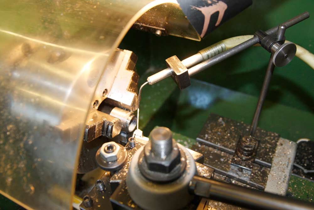
                          Could that be a Tangential tool in your picture?
                          I have become even more of an “expert” on these tools, as I have got about 90% of the work done on a batch of 6 of the superior version. One of them has your name on it to replace the “loan/trial” one. Myford fit do you?
                          chriStephens
                          PS just to fit in with the travelling steady , I used one once, never found it necessary since.
                          No one has yet mentioned the travelling steady with two rollers and has the cutting tool as part of the arrangement ie the Roller Box. Seems to me that this is a superior way of doing things and removes the argument over where the TS’s fingers should be.
                          #65692
                          mgj
                          Participant
                            @mgj
                            No – its not A tangential tool. Its THE tangential tool. Still munchng metal. Myford fit is fine thank you kind sir. Cuts so well that even on the big chinaman it woun’t be outclassed. Shift a lot of metal they do. (Tangential tooling is engraved on me ‘eart nowadays, engraved on me ‘eart it is)
                             
                            I’m not familiar with the box type of TS , but from what you are saying its very like the Chronos thing I’m on about – in principle, not necessarily in detail – where tool and fingers/support (wahtever sort) are integral to the set up. I’ll bet it is very god.
                             
                            The problem I’m thinking is less one of support and more one of size and access. Machine a replacement for a milling machine leadscrew, and its a 1″ dia thing. Pop a TS on it, somewhere close to the tool, chomp positively and you have to work quite hard to cock it up.Try and do the same thing on one of Grays tiny relatively long camshaft blanks and it all gets a bit more critical, and a different approach may well be called for.
                             
                            However, whats not to be deviated from is – 3 points of contact, obviously, and has been so for the better part of a thousand years, (unless there is a very specific reason not to) and get the forces in line in so far as is possible.
                             
                            Rules, as Dr Johnson famously said, are for the guidance of the wise, and the blind obedience of fools.

                            Edited By mgj on 19/03/2011 09:38:22

                            #65698
                            mgj
                            Participant
                              @mgj
                              Tell you the other thing we haven’t looked at Gray – thats longitudinal adjustment. Over squinge the tailstock and add heat and thats about as sure a way of introducing a swerve as one can get – particularly as no tailstock is ever “perfectly” aligned, so a moment will be introduced.
                               
                              Too slack and a bit of chatter creeps in?  I have seen people, when chatter creeps in adjusting steadies, when possibly they should be adjusting tailstocks?

                              Edited By mgj on 19/03/2011 11:47:36

                            Viewing 13 posts - 51 through 63 (of 63 total)
                            • Please log in to reply to this topic. Registering is free and easy using the links on the menu at the top of this page.

                            Advert

                            Latest Replies

                            Viewing 25 topics - 1 through 25 (of 25 total)
                            Viewing 25 topics - 1 through 25 (of 25 total)

                            View full reply list.

                            Advert

                            Newsletter Sign-up